2018 3rd International Conference on Computational Modeling, Simulation and Applied Mathematics (CMSAM 2018) ISBN: 978-1-60595-035-8
Structure Design and Simulation Study on the Symmetric Optical Path
Reflection Current Sensor
Dai WAN
1,*, Yu-yang YAN
2, Miao ZHAO
1, Tao
PENG
1,
Xu-jin DUAN
1and Liu-ming MAO
11
State Grid Hunan Electric Power Company Limited Research Institute, Changsha, China
2
Electrical Engineering College, Huazhong University of Science and Technology, Wuhan, China
*Corresponding author
Keywords: Optical current sensor, Faraday effect, Structure design, Simulation, Sensitivity.
Abstract. Optical current sensor is received much attention by its good performance on safety and anti-interference. It displaces the traditional electromagnetic current transformer in power grid. However the optical current sensor is limited by its shortcoming in stability and reliability. It is result in big linear birefringence and low sensitivity. In this paper a new structure of optical current sensor is designed to achieve higher sensitivity about 580 times than traditional structure. The system transmission field has been obtained by simulating the transmittance of light propagating through optical sensing head by COMSOL software. The result obtained from the present work is useful for further research on the optical fiber current sensor.
Introduction
The current sensor is a key part in the power network, which is related to the safe operation of the power grid. In the past 100 years, the traditional electromagnetic current transformer has been widely used due to its mature measurement technology, simple structure and not easy to damage. With the increasing of power grid scale and the continuous development of the operating mechanism, it exposed low-security[1], severe electromagnetic interference[2], low environmental friendliness, magnetic saturation phenomenon[3], low measuring precision[4,5], high cost, difficult to assemble and so on, due to the particularity of its structure and the conditions of use.
The shortcomings of traditional current sensors have prompted people to explore more advanced current sensors. In the 1960s, with the technology of semiconductor integrated circuit technology, laser technology and optical communication technology emerged, the technology of optical current sensing was rapidly developed. Theoretically, the optical current sensor has the function of traditional electromagnetic current sensor and can overcome the above shortcomings[6,7]. However, the linear birefringence in optical materials and low sensitivity to current magnetic field have been the main reason to limit the development of optical current sensor[8].
At present, the study of all-fiber current sensing technology mainly focuses on the field of large
current measurement, which is generally in the range of 102A-106A, and the stability is not
Theory
Faraday Effect
Working principle of optical current sensor is based on Faraday effect .Faraday effect is mainly due to the magnetization of the external magnetic field, then the optical material has a magnetic moment, at this point, the polarized light of the electromagnetic field will interact with the magnetic moment in the optical material, which affect the electric field distribution of the light, and the macroscopic expression is the polarization rotation of the light wave[12].The magnitude of the external magnetic field is reflected by the accurate measurement of Faraday deflection angle, which can work out the current that generates the magnetic field further.
Optical material dielectric constant ε will change after the material gets the magnetic moment, and the material’s magnetic moment is related to the intensity of magnetization, so the change of dielectric constant can be described by intensity of magnetization M. According to the properties of tensors and
Onsager relation[12] εij(M)= εij(-M),the change of the dielectric constant ε can be expanded by the
power series of M, the components of the dielectric constant tensor can be expressed as:
' '
11 12 13 12 13
' '
21 22 23 21 23
' '
31 32 33 31 32
0 0 0 r i (1)
For the optical crystals selected by optical current sensor, the symmetry is higher than that of the tetragonal crystals, and the distribution of the material is uniform, so that there are ε11=ε22, ε12=-ε21, ε13=ε31=ε23=ε32=0. So from Eq.1, we can get:
0 0 0 0 r i i (2)
In the formula, suppose that the z axis is set as the direction of the optical axis, the xy plane is the cross section of the optical crystal, the dielectric constant ε11=ε22=ε33=ε along the x, y and z axis. δ is
the magnetic polarization coefficient, which is related to the external magnetic field. The polarized light meets Maxwell's equations in the optical fiber.
t j t B E D H (3)
In the formula: B is the magnetic induction intensity; D is the displacement vector. The expression of linearly polarized input light is:
( ) 0 ( ) 0 e e n i t c n i t c s r s r E E H H (4)
In the formula: E0 is the amplitude of the wave electric field; S is the unit vector of the light wave
direction; H0 is the amplitude of the optical magnetic field.
The expression for the speed of light in a vacuum is c2=(μ0ε0)-1.From Eq 2 and 3,we can get:
2
[( ) ] r
n
2
0
0
0 0 0
x x
y y
z
E i E
n E i E
E (6)
The matrix operation of Eq. 6 can be:
2
n (7) Eq. 7 is introduced into Eq. 6 first and second series equations:
y x
E iE (8) Eq. 8 represents two beams of circularly polarized light which rotate to the opposite and propagate at different speed c/n+ and c/n- along the optical axis direction. After a certain distance, there is a phase difference between the two beams of light, the two circularly polarized light is still linear polarized after the merger, and has a deflection angle related to the initial linearly polarized light.
Suppose the line polarized light propagates l distance along z direction, then the polarization
deflection angle is θ. If the initial polarization of the polarized light is along the X-axis, tanθ=Ey/Ex.
π( )
arctan y
x
E n n
l E
(9)
From Eq.7 and Eq. 9, we can get:
0 π l VHl n
(10)
In the formula: V is the Field constant for optical materials/rad·A-1. H is the magnetic field
generated by the test current.
Linear Birefringence Effect
If the dielectric constant of optical materials is not equivalent, a singular phenomenon occurs in the transmission of linear polarized light, which is called linear birefringence effect. Suppose that the
cross section of the optical crystal εx≠εy. From Eq. 6, we can get:
2 1 2 2
[( ) ( ) 4 ]
2 x y y x
n (11)
And the result of Eq. 6 is:
1 ( )
y x
E i E (12)
Eq(12): 2 2 2
2
( ) ( ) 4 ]
x y x y x
n
Eq. 12 represents a beam of elliptically polarized light. It can be seen that due to the existence of linear birefringence, linearly polarized input light will turn into an elliptical polarized light.
Structure Design
We first designed a high sensitivity optical current sensor experiment system with a new type of structure, as shown in Figure 1, which can be named as symmetric optical path reflective optical current sensor. The system consists of light source, Glan prism, fiber optic coupler, sensing fiber, self-focusing lens, symmetrical optical path reflective sensing head, Wollaston prism, and light detector.
In this system, the light from laser become linear polarized light by Glan prism, then a Faraday
decomposed by analyzer is converted into a current signal after the light detector, eventually can get the accurate light polarization angle by calculating these two signal.
Figure 1. Optical current sensor.
In traditional optical sensing head, the linear birefringence is very large and the sensitivity of the magnetic field is low, which is the main reason for the bad stability and reliability of optical current sensor. So we design a new type of symmetric optical path reflective sensing head, compared with the traditional linear structure, this structure can improve the sensitivity about 800 times, so that can improve the accuracy and stability of full optical fiber current sensor.
Optical path reflective optical current sensing head is composed of electric solenoid and cylindrical quartz crystal, inner diameter of solenoid is 30 mm, outside diameter is 40 mm, length is 230 mm, the
center of the cylinder is empty, and the number of turns of each solenoid is n1 = 1500.The magnetic
field in the solenoid is generated centrally(related to the number of turns of per unit length), and then put the quartz glass with two-sided reflector on the solenoid axis.
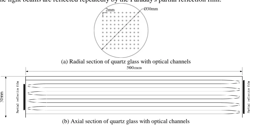
Figure 2 (a) and Figure 2 (b) are the radial section and axial section of the cylindrical quartz crystal in optical path reflective optical current sensing head. The cross section of the cylindrical quartz crystal is a circle with a radius of 30mm, and the axial length of quartz crystal cylinder is 500mm.
Because the optical channel of this optical current sensing head is high index of refraction pure quartz rod, the envelope is low index of refraction glass, linear polarized light will only be transmitted in high index of refraction quartz channel. Processing the glass rod into array and plating Faraday's partial reflection film on the two terminals so that can assure linearly polarized light is transmitted from the optical channel to the end surface and is reflected into the adjacent light channel, and it also can eliminate the effect of the phase shift of the reflected light on experimental results. According to the non-reciprocity of Faraday optical effect, the Faraday rotation angle will increase exponentially after the light beams are reflected repeatedly by the Faraday's partial reflection film.
(a) Radial section of quartz glass with optical channels
(b) Axial section of quartz glass with optical channels Figure 2. The symmetric optical path reflection current sensor.
Using ampere circuital theorem to analyze the relationship between external magnetic field and test current in Eq. 10. Eq. 10 can be simplified as:
1 2
Vn n I
[image:4.595.86.513.507.717.2]In the formula: n1 is the number of turns of the electric solenoid, n2 is the number of optical
channels in the sensing head.
Simulation
In this paper, the system transmission field has been obtained by simulating the transmittance of light propagating through optical sensing head by COMSOL software, COMSOL software is based on the finite method, and the simulation of real physical phenomena is realized by solving partial differential equations (single field) or partial differential equations (multiple fields).In this experiment, the Maxwell equations with time variables were transformed into difference equations in space by COMSOL. The electric field (or magnetic field) component at each grid point in difference equation are only related to it’s adjacent magnetic field or (electric field) component and the value of the point at which the point was taken. The electric and magnetic components of each point in the grid space are calculated at each time step, which can directly simulate the propagation of electromagnetic waves and their interaction with objects as time moves forward.
Space electromagnetic field parameters are presented according to the spatial grid in difference equation, so just setting the appropriate parameters of the this field, anisotropy, dispersion characteristics, nonlinear can accurately be simulated[13].
Traditional Linear Structure Optical Current Sensor Simulation
Based on the application example of traditional linear structure optical current sensor, the simulation model is designed. Set the cable as the copper cylinder, the radius is 1cm, the height is 1m, the curret is 1A, the cable axis along the z-axis in the xyz coordinate system, the radial section is in the xy plane,
so the current density is set to jx = jy = 0, jz = 3183 A/m2. According to these parameters, the material
property and the electrical are drawn. The cylinder with 0.2m radius and 1.4m high is set to be full of air, and the outermost layer is PML, as the calculation area. Shown in Figure 3 is the simulation calculation results of Hy in the xy plane, the depth of the color indicates the magnitude of the magnetic field and the plus or minus represents the direction. From Figure 3, we can see that the radial cross section of the cable has opposite magnetic fields and the more far away from cable the smaller magnetic field intensity. Because only one parameter can be chosen at a time in the software, the magnetic field intensity of x direction is not shown in the figure, the calculation results show that Hx
[image:5.595.213.382.524.637.2]distribution is consistent with Hy.
Figure 3. The magnetic field of traditional linear structure optical current sensor.
Symmetrical Optical Path Reflection Structure Simulation
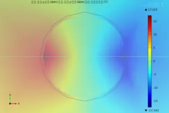
According to the design of the symmetrical optical path optical current sensor model, the simulation model of the reflector structure is shown in Figure 4.When the model is established, a uniformly distributed 10*10 line array is embedded in the solenoid, the shortest spacing between each optical
channel is 2mm, the sensor head is 3cm, the current density is set to jx = -652174* y/(x2 + y2) *0.5
A/m2, jy = 652174 */(x2 + y2)* 0.5 A/m2, jz = 0. By calculating it’s simulation model, the vector
integral of the magnetic field along the optical path is 1.4449 * 105A/m, and Faraday magneto-optic
deflected angle is θ = 0.8578rad upon the stimulation by a red laser with a wavelength of 650nm. According to the calculation results, the sensitivity of the symmetric optical path reflection structure is 580 times higher than that of the linear structure.
[image:6.595.109.486.226.346.2]
(a) Symmetrical optical path optical current sensor model (b) Simulation result of Hz Figure 4. Magnetic field distribution of optical current sensor.
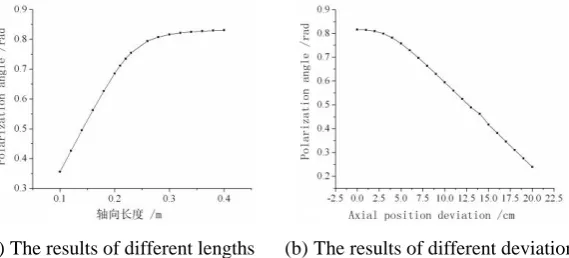
In the design of the sensing head, set the length is 3 cm, but in the actual production may produce different size of the sensing head, different length of the sensing head will affect the measurement of Faraday magneto-optic deflected angle.
Supposing that the current in the circuit is 1A, and the results of different length of sensing head is shown in Figure 5 (a), from the calculation results, it can be found that when the axial length of sensor head is less than solenoid, the system will reduce the sensitivity; When the sensing head length up to 50 cm or more, curve flatten out gradually, the sensitivity of the system tends to be stable, the measurement error keep within 0.1%, therefore the length of the sensing head should be set at least 50 cm or more.
If met the requirement of the sensing head size, the deviation between the midpoint of sensor head and the solenoid which may be caused by carelessness also impacts the result. Supposing that the current in the circuit is 1A, and the results of different deviation is shown in Figure 5 (b), from the calculation results, it can be found that there will be a huge influence when the position of sensor head doesn’t put in the right place and with the increment of deviation, the error will be more and more big, the deviation within 1 cm, the error is less than 0.2%.
[image:6.595.158.443.596.725.2]
Summary
In this paper, an optical current sensor test system of symmetrical optical path is designed, and it’s simulated by COMSOL software. By comparing with the traditional linear optical current sensor, this sensor can solve the problem of accurate measurement of small current, and the conclusion is as follows:
(1) The symmetric optical path reflection current sensor is 580 times higher than that of the traditional linear current sensor, it expands the range of optical fiber current sensor, and solves the technical problems of measuring small current with optical fiber current sensor.
(2) The effect of linear birefringence on the measurement is reduced by the dual structure.
(3) The precision of the symmetric optical path reflection current sensor is high. The length of the sensor head should be at least 50cm; The axial position deviation should be kept within 1cm and the error of measurement will be less than 0.2%.
References
[1] Liu Ye, Wang Caitang, Su Yanmin. New Progress of Optical Current Transformer Application in Power System [J]. Power System Automation, 2000, 17: 60-64.
[2] Emerging Technologies Working Group, Fiber Optic Sensors Working Group. Optical Current Transducers for Power Systems: A Review[J]. IEEE Transaction on Power Delivery, 1994, 9 (4): 1778-1787.
[3] Wan Dai, Zhong Lisheng, George Chen. Experiment and Simulation Study on A New Structure
of Full Optical Fiber Current Sensor [C]. 2017 2nd International Conference on Computational Modeling, Simulation and Applied Mathematics, 2017: 65-70.
[4] Fabio Vieira Batista de Nazare, Mazare Martins Werneck. Hybrid Optoelectronic Sensor for Current and Temperature Monitoring in Overhead Transmission Lines[J]. IEEE Sensors Journal, 2012, 12 (5): 1193-1194.
[5] Byoungho Lee. Review of the present status of Optical Fiber Sensors[J]. Optical Fiber Technology, 2003, 9:57-79.
[6] Apurba Ghosh, Punya Brata Dutta Gupta, Ajit Kumar Mandal. Development of a Fiber-Optic Current Sensor with Range-Changing Facility Using Shunt Configuration[J]. IEEE Sensors Journal, 2013, 13 (4): 1347-1354.
[7] Li Bingjun, Li Lijing. An Overview of the Optical Current Sensor[C]. 2012 International Conference on Computer Science and Electronics Engineering. 2012, 3: 202-206.
[8] Wan Dai, Zhong Lisheng, Qi Fei. DC Characteristics of the Symmetric Spiral Nested Full Optical Fiber Low Current Sensor [J]. Transactions of China Electrotechnical Society, 2016, 31 (17): 196-206.
[9] Qin Ran, Wang Qianqian, Yang Shihai. Study on Error Characteristics of All Optical Fiber Current Transformer in Field Operation [J]. Jiangsu Electrical Engineering, 2013, 32 (02): 7-9+14.
[10] Chen Minming, Lu Shufeng, Bao Yushu. Design of Real-time Error Analysis System for Optical current transformer [J]. Jiangsu electrical engineering, 2013, 32 (02): 47-49+53.
[11] Chen Wenzhong, Lin Yi, Zhou Jian. Accuracy Calibration of All Optical Fiber Current Transformer in Digital Substation [J]. East China Electric Power, 2009, 37 (12): 2022-2024.
[12] Liu Gongqiang, Yue Zhiqiang, Shen Defang. Magneto Optics [M]. Shanghai: Shanghai Science and Technology Press, 2001 (4): 30-31.