© 2016, IRJET | Impact Factor value: 4.45 | ISO 9001:2008 Certified Journal
| Page 1451
Seismic vulnerability of RC framed structure under irregular
conditions
Mohseena Tazeen
[1], Tejashree Kulkarni
[2], Tauseef Honnyal
[3][1]
Mtech Student, Dept Of Structural Engineering SIET Vijayapur Karnataka, India
[2]Assistant Professor, Dept Of Structural Engineering SIET Vijayapur Karnataka, India
[3]
Assistant Professor, Sardar Patel College Of Engineering, Andheri, Mumbai, India
---***---Abstract - Investigations of past and recent earthquake
damage have illustrated that the building structures are vulnerable to severe damage or collapse during moderate to strong ground motion. This research quantifies the performance of the seismically irregular building by subjecting pushover analysis and static analysis results of different buildings. The performance of the buildings is assessed as per the procedure prescribed in ATC-40 and FEMA-356.
Key Words: Plan irregularity, vertical irregularity, Etabs, pushover analysis, seismic performance.
1. INTRODUCTION
Every earthquake leaves a trail of miseries by the loss of life and destruction, but it provides lessons to the human society particularly engineers, architects, builders and administrators for improving design and construction practices. An earthquake with a magnitude of six is capable of causing severe damages of engineered buildings, bridges, industrial and port facilities as well as giving rise to great economic losses. Several destructive earthquakes have hit in both historical and recent times from distant and near earthquakes Many buildings in the present scenario have irregular configurations both in plan and elevation, which in future may subject to devastating earthquakes. In case, it is necessary to identify the performance of the structures to withstand against disaster primarily due to earthquake. A detailed study of structural behavior of the buildings with irregularities is essential for design and behavior in earthquake Therefore a comprehensive evaluation of the effect of vertical and horizontal irregularities on the seismic demand of building structures is greatly needed Pushover analysis is an approximate method in which the structure is subjected to continuously increasing lateral forces with invariant height wise distribution until the target displacement is reached.
2. Review of Literature
(1) Ravikumar C M, Babu Narayan K.S, Sujith B V, Venkat Reddy D (2012)
In their paper entitled “Effect of Irregular Configurations on Seismic Vulnerability of RC Buildings” has discussed about the behaviour of building during earthquake. The entire modeling, analysis and design was carried out by using ETABS 6.0 nonlinear version software.
(2) Jag Mohan Humar, Soheil Yavari, and Murat Saatcioglu
In the paper entitled “DESIGN FOR FORCES INDUCED BY SEISMIC TORSION” showed that eccentricities between the centers of rigidity and centers of mass in a building cause torsional motion during an earthquake.Results of analytical studies, which show that the new proposals would lead to satisfactory designs .
(3) Dr. B. G. Naresh Kumar, Avinash Gornale and Abdullah Mubashir
In the paper entitled “Seismic Performance Evaluation of R c-Framed Buildings - An Approach To Torsionally Asymmetric Buildings” showsstudied the performance of the torsionally balanced and torsionally unbalanced buildings. It is found that the plastic hinges are more in case of models where stiffness of walls neglected than the models where stiffness of infill walls is considered.
3. Objectives and methodology
To study the behavior of structure under plan and vertical irregular conditions.
To identify the performance levels of the structure through pushover curves.
© 2016, IRJET | Impact Factor value: 4.45 | ISO 9001:2008 Certified Journal
| Page 1452
4. Pushover analysis
Pushover analysis is an approximate method in which the structure is subjected to continuously increasing lateral forces with invariant height wise distribution until the target displacement is reached. Pushover analysis consists of series of sequential elastic analysis, superimposed to approximate a force - displacement curve of the overall structure. An already known lateral load pattern which is distributed along the building height is then applied. The lateral forces are increased until some members of the structure yields. Then changes are made n the structural model to reduce the stiffness of yielded members and lateral forces are again increased until some other members yield. The process is continue until a control displacement at the top of building reaches a certain level of deformation or structure become unstable. The roof displacement is plotted with base shear to get the global capacity curve.
Pushover analysis can be performed as force - controlled. In force - controlled pushover procedure, full load combination is applied. The steps to be followed in seismic performance evaluation of structures and rehabilitation of structures are given below
1. Select the performance objective of the building as required by owner to achieve for given seismic hazard.
2. Review the existing building conditions by visual inspections, existing drawings, and tests on structure and perform preliminary evaluation of the building.
3. Formulate a strategy for achieving the desired performance objective for given level of seismic hazard.
4. Assess the performance of the retrofitted structure with any analysis procedures.
5. Check the performance of the structure with desired performance objective.
6. If performance objective is not achieved, formulate new strategy and assess the performance of the structure again. Do the above process till desired performance objective is achieved.
4.1
Performance objectives
Performance objective specifies the desired seismic performance of building. Seismic performance is described by designating the maximum allowable damage state for an identified seismic hazard.
Fig-1: Different stage of plastic hinge
Table-1: Different stage of plastic hinge
Nonstructural performance level
Damage description
Operational
Non-structural systems are in place & functioning. All the equipments & machinery will be in working conditions.
Immediate occupancy[IO]
Disruption of non-structural elements & functionality is not considered.
Life Safety [LS]
Considerable damage to non-structural elements. Very low risk to life from it.
Hazards reduced
Extensive damage to the non-structural elements. Life risk is more due to collapse of elements.
4.2 Purpose of doing pushover analysis
The pushover analysis is expected to provide info on many characteristics which cannot be obtained from an dynamic or static (elastic) analysis.
Estimates of the deformations requests to components that must misshape On elastically in place should scatter those vitality imparted of the structure.
Outcomes of the quality crumbling about singular components on conduct technique of the structural system.
Identification of the basic areas on which those deformity requests need aid expected on make secondary Also that must ended up those keep tabs through itemizing.
Identification of the quality spasmodic clinched alongside arrangement rise that will prompt progressions in the element aspects in versatile range.
Estimates of the bury story drifts that represent quality alternately firmness discontinuities and that might make used to control those harms Also on assess P- delta impacts.
© 2016, IRJET | Impact Factor value: 4.45 | ISO 9001:2008 Certified Journal
| Page 1453
structural systems, every last one of connections, Alsofirm non-structural components about noteworthy strength, and the establishment framework.
5. Description of frame buildings
Three dimensional reinforced concrete moment resisting frame buildings has been taken for the study. The building consists of eight stories. All columns in all models are assumed to be fixed at the base for simplicity. The height of ground floor and upper floor is 3.0 m. Slab of all the models is modeled as rigid diaphragm element of 0.15m, for all stories considered. Live load on floor is taken as 3KN/m2 and on roof is 1.0KN/m2.Floor finish on the floor is 1KN/m2. Wall thickness is of 230mm on all the beams. The seismic weight is calculated conforming to IS 1893-2002(part-I). The unit weights of concrete is taken as 24KN/m3 .The grade of concrete for column, beam and slab is M-25. The building is special moment resisting frame considered and intended for residential use.
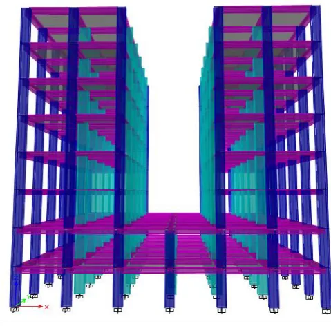
[image:3.595.316.556.387.623.2]Three models are considered for the analysis , one plan irregular “C” shapes , one vertical irregular “U” type and these two compared with regular building on Hard Soil strata. All these structure’s results compared in earthquake zone III, IV and V .
Fig-2: Shows the plan of regular building
Fig-3:
Shows the “C” type building, Irregular plan
[image:3.595.38.262.405.626.2]© 2016, IRJET | Impact Factor value: 4.45 | ISO 9001:2008 Certified Journal
| Page 1454
Table-2: Shows Maximum Values As Per Linear Static Analysis In Seismic Zone-V
Mode
ls Base shear (kN) Displacement (mm) Drift (mm)
C-V 1196.7209 15.944 0.000847
U-V 1151.0861 15.262 0.00084
R-V 1424.7076 15.51 0.000835
After linear static analysis regular building (R-V) shows maximum value of base shear, plan irregular building “C” shows maximum displacement and drift.
Chart-1: Shows Base Shear values
Chart-2: shows Displacement values
Chart-3: Shows Drift of respective models
Table-3: Shows pushover results for the models considered
models Monitored
Displacement (mm) Base Force (kN)
C 302.436 4570.0863
U 330.028 2873.9824
R 313.533 4960.3228
Chart-4: Shows pushover curves for three described models.
6. CONCLUSIONS
For zone-V as per static analysis results, base shear of regular building shows 15-19% maximum Base shear compare to irregular “U” and “C” type building.
“C” types building shows maximum displacement 15.94mm and drift 0.000847mm.
The results of analysis for RC frame plan irregular building indicates that the storey drift for model “C” with rectangular columns shows a much higher storey drift at third storey level.
In pushover analysis all models lies between LS and CP. Regular building “R” shows greater shear
© 2016, IRJET | Impact Factor value: 4.45 | ISO 9001:2008 Certified Journal
| Page 1455
7. REFERENCES
1. Ravikumar C M, Babu Narayan K.S, Sujith B V, Venkat Reddy D (2012). “Effect of Irregular Configurations on Seismic Vulnerability of RC Buildings”. Architect Research, volume 2, issue 3, pp 20-26.
2. Pankaj A. and Manish S. (2006) “Earthquake Resistant Design of Structures”, ISBN-81-203-2892-2. Prentice Hall of India (pvt), New Delhi, 534-540.
3. ATC-40, “Seismic Evaluation and Retrofit of Concrete Buildings”, Applied Technology Council, November 1996. 6. FEMA-356, Pre standard and commentary for the seismic rehabilitation of buildings, Federal Emergency Management Agency, November 2000.
7. IS: 1893 (Part 1): 2002, Indian Standard Criteria for Earthquake Resistance Design of Structures, Part 1 General provisions and buildings (Fifth
Revision), Bureau of Indian Standards, New Delhi.
8. IS 456:2000, ―Plain and Reinforced concrete – Code of practice, Bureau of Indian Standards, New Delhi.
BIOGRAPHIES
1. Ms. Mohseena Tazeen Obtained Bachelor of Engineering (Civil Engineering) from Veerappa Nisty Engineering College Shorapur, Karnataka and Master in Technology (Structural Engineering)from Secab Institute of Engineering and Technology Vijayapur Karnataka, India
Email – [email protected]
2. Ms. Tejashree Kulkarni, presently she is working as Assistant Professor in Civil Department of Secab Institute of Engineering and Technology Vijayapur India
Email – [email protected]
3. Mr. Tauseef Honnyal, presently he is working as Assistant Professor in Department of Structural Engineering of Sardar Patel College Of Engineering, Andheri (W), Mumbai, India.