© 2015, IRJET ISO 9001:2008 Certified Journal Page 660
Implementation of simulation based novel PWM scheme for harmonic
reduction in three phase voltage source converter.
Madake Rajendra
1, Nimbalkar Nikita
2, Dr. A.M.Mulla
3, Patil Swapnil
41
Student, Electrical Engineering Department, ADCET, Ashta, Sangli (MH), India
2Student, Electrical Engineering Department, ADCET, Ashta, Sangli (MH), India
3Principal, Electrical Engineering Department, ADCET, Ashta, Sangli (MH), India
4Asst. Prof, Electrical Engineering Department, ADCET, Ashta, Sangli (MH), India
---***---Abstract -
This paper works on implementation ofsimulation based voltage source converter with ISPWM technique. This VSC is based on a new pulse wide modulation technique called as inverted-sine PWM (ISPWD). The propose ISPWM technique can be used to control voltage source converter. This switching technique used a sinusoidal reference signal and an inverted-sine as carrier signal. The ISPWM technique generates low voltage harmonic distortion as compare with conventional sinusoidal PWM technique. . The insulated gate bipolar transistor (IGBT) was used as the switching device. The modeling and simulation of the work were implemented by MATALAB/Simulink. Simulation results for different desired output frequencies. The paper presents also the way to reduce the harmonics using the proposed improved sinusoidal
pulse width modulation (ISPWM) and comparison with
traditional sinusoidal pulse width modulation (SPWM).
Key Words:
PWM, SPWM, ISPWM, MATLAB
1. INTRODUCTION
Voltage source converter is a power electronic device which converts electrical dc supply in to electrical ac supply. There are two main types of switching modes of inverter i.e. square wave and Pulse width modulation. In square wave inverter have problem of harmonic. In Pulse width modulation refers to a method of carrying information on train of pulses and the information be encoded in the width of pulses. The AC voltage is dependent on two parameters i.e. amplitude and frequency. It is essential to control these two parameters. The most efficient to control these parameters are by using Pulse Width Modulation techniques. In order to generate the gating signals using Pulse Width Modulation Techniques. We compare the reference signal amplitude with carrier signal amplitude. The fundamental frequency of output voltage is determined using the reference signal frequency.
Conventionally, to generate this pulses, triangle wave as a carrier signal is compared with the sinusoidal wave, whose frequency is the desired frequency. In this paper three-phase inverters and their operating principles are analyzed in detail. Sinusoidal pulse width modulation
is widely used in power electronics to digitize the power so that a sequence of voltage pulses can be generated by the on and off of the power switches. The pulse width modulation inverter has been the main choice in power electronic for decades, because of its circuit simplicity and rugged control scheme SPWM switching technique is commonly used in industrial applications SPWM techniques are characterized by constant amplitude pulses with different duty cycle for each period
The paper presents a novel PWM scheme for controlling the output of an inverter. The control scheme uses an inverted-sine carrier that helps to maximize the output voltage for a given modulation index. The harmonic content in the proposed inverted-sine P W M (ISPWM) scheme is less compared to the conventional SPWM.
2. PROPOSED WORK
The objective of this paper is to present “Implementation of simulation based novel PWM scheme for harmonic reduction in three phase voltage source converter”. Scheme for ISPWM for pules generation for Voltage source convertor.
Following figure shows the schematic block diagram of proposed work
Fig.1 Block Diagram of Proposed Work
2.1 Voltage Source Converter:
© 2015, IRJET ISO 9001:2008 Certified Journal Page 661 and magnitude of the output voltages allows effective
control.
Schematic diagram of three phase inverter is shown in below figure. DC supply used as an input of three phase inverter. Three phase inverter block consist a hex bridge with LC filter circuit. The ac output of inverter is given to the load. The output voltage can be varied either by varying DC input voltage or by controlling the gain of the inverter with PWM. The output voltage waveforms of ideal inverters should be sinusoidal. However, the practical inverters will have non-sinusoidal waveforms due to harmonics. In control circuit used for SPWM gate pulse generation.
Fig.2 Block Diagram of three phase inverter.
2.2 SPWM Technique
Based on the PWM concept, if the duty cycle is changed sinusoidal, a sinusoidal voltage will be generated at the output. Voltage Source Converters (VSC) is widely used as a basic component in custom power devices. But this power devices produce voltage harmonics due to switching operation of power electronic converters. The harmonics in the output voltage of power electronic converters can be reduced using Pulse-Width Modulation (PWM) switching techniques.
In the most straightforward implementation, generation of the desired output voltage is achieved by comparing the desired reference waveform (modulating signal) with a high-frequency triangular ‘carrier’ wave as depicted schematically in below figure. Depending on whether the signal voltage is larger or smaller than the carrier waveform, either the positive or negative dc bus voltage is applied at the output. Note that over the period of one triangle wave, the average voltage applied to the load is proportional to the amplitude of the signal (assumed constant) during this period. The resulting chopped square waveform contains a replica of the desired waveform in its low frequency components, with the higher frequency components being at frequencies of a close to the carrier frequency. Notice that the root mean square value of the ac voltage waveform is still equal to the dc bus voltage, and hence the total harmonic distortion is not affected by the PWM process. The harmonic components are merely shifted into the higher frequency range and are automatically filtered due to inductances in
the ac system.
Fig.3 Firing pulse generation in proposed SPWM.
2.3 ISPWM Technique
The harmonics in the output voltage of converters can be reduced using Pulse-Width Modulation (PWM) switching techniques. PWM methods reduce the harmonics by shifting frequency spectrum to the vicinity of high frequency band of carrier signal. In the case of sinusoidal PWM (SPWM) scheme, the control signal is generated by comparing a sinusoidal reference signal and a triangular carrier. The SPWM technique, however, inhibits poor performance with regard to maximum attainable voltage and power.
A novel PWM technique, called Inverted-Sine PWM (ISPWM), for harmonic reduction of the output voltage of ac-dc converters is presented in. In addition, the control scheme based on ISPWM can maximize the output voltage for each modulation index .In this paper, ISPWM switching technique has been developed for controlling of VSC based inverters which has lower Total Harmonic Distortion (THD) than conventional techniques.
The Advantages Of The Topology Are:
• Reduced number of dc sources. • High speed capability© 2015, IRJET ISO 9001:2008 Certified Journal Page 662 Fig.4 Firing pulse generation in proposed ISPWM
2.4 Modulation Index
2.4.1 Amplitude Modulation Index
Modulation index is the ratio of peak magnitudes of the modulating waveform and the carrier waveform. It relates the inverter’s dc-link voltage and the magnitude of pole voltage (fundamental component) output by the inverter. Now let ‘sin(mVω)’ be the modulating signal and let the magnitude of triangular carrier signal vary between the peak magnitudes of +Vc and -Vc. The ratio of the peak magnitudes of modulating wave (Vm) and the carrier wave (Vc) is defined as modulation-index (m). In other words:
M=Vm/Vc
2.4.2 Frequency Modulation Index
Frequency Modulation index is the ratio of the frequency of carrier waveform fc frequency and of the modulating waveform fm and is given by:
N=fc/fm
The frequency modulation index should not be even number it should be odd number as even number cancel each other.
2.4.3 Over-Modulation
When the peak magnitude of modulating signal exceeds the peak magnitude of carrier signal (resulting in m >1), the PWM inverter operates under over-modulation. During over-modulation the fundamental component of the pole voltage increases slightly with increase in modulation index but the linear relation between them, no longer continues. Also, lower frequency harmonics crop up in the pole-output waveform. It may easily be seen that for ‘m’ very high (say m = infinity), Over modulation is generally not preferred because of the introduction of lower frequency harmonics in the output waveform and subsequent distortion of the load current.
3 Matlab SIMULATION
3.1 MATLAB Simulation model of SPWM
Inverter
Fig.5 Simulink Model for SPWM Inverter
Above fig shows the Simulink Model for SPWM Inverter fed Induction Motor. Here we developed a DC to AC inverter fed to induction motor in Simulink / Matlab with a three phase PWM inverter controlling both the frequency and magnitude of the voltage output. For generation of PWM pulses the technique was used comparing sinusoidal control voltage (at the desired output frequency and proportional to the output voltage magnitude) with a triangular waveform at a selected switching frequency.
3.1.1 Development of Sinusoidal PWM
Fig.6 Simulink Model for SPWM tech.
© 2015, IRJET ISO 9001:2008 Certified Journal Page 663 intersects the triangular waveform. The crossing positions
determine the variable switching times between states. N three-phase SPWM, a triangular voltage waveform (VT ) is compared with three sinusoidal control voltages (Va, Vb, and Vc), which are 120̊ out of phase with each other and the relative levels of the waveforms are used to control the switching of the devices in each phase leg of the inverter.
Fig.7 SPWM TECHNIQUES.
3.1.2 SIMULATION OUTPUTS
SPWM pulses
Fig.8 SPWM PULSES.
Total harmonic distortion of SPWM
Fig.8 THD of SPWM
3.2 MATLAB Simulation model of ISPWM
Inverter.
Fig.9 Simulink Model for ISPWM Inverter
Above fig shows the Simulink Model for ISPWM Inverter fed Induction Motor. Here we developed a DC to AC inverter fed to induction motor in Simulink / Matlab with a three phase PWM inverter controlling both the frequency and magnitude of the voltage output. For generation of PWM pulses the technique was used comparing sinusoidal control voltage (at the desired output frequency and proportional to the output voltage magnitude) with a inverted sine waveform at a selected switching frequency.
© 2015, IRJET ISO 9001:2008 Certified Journal Page 664 Fig.10 Simulink Model for ISPWM tech.
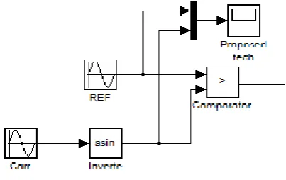
Above fig shows the Simulink Model for ISPWM Inverter. The inverted sinusoidal pulse-width modulation (ISPWM) technique produces a sinusoidal waveform by filtering an output pulse waveform with varying width. A high switching frequency leads to a better filtered sinusoidal output waveform. The desired output voltage is achieved by varying the frequency and amplitude of a reference or modulating voltage. The variations in the amplitude and frequency of the reference voltage change the pulse-width patterns of the output voltage but keep the sinusoidal modulation. A low-frequency sinusoidal modulating signal is compared with a high frequency inverted sine, which is called the carrier signal. The switching state is changed when the sine waveform intersects the inverted sine waveform. The crossing positions determine the variable switching times between states. n three-phase ISPWM, a triangular voltage waveform (VT ) is compared with three sinusoidal control voltages (Va, Vb, and Vc), which are 120̊ out of phase with each other and the relative levels of the waveforms are used to control the switching of the devices in each phase
leg of the
[image:5.595.44.557.110.792.2]inverter.
Fig ISPWM TECHNIQUES.
3.2.2 SIMULATION OUTPUTS
[image:5.595.307.566.110.518.2]
ISPWM pulses
Fig.11 ISPWM PULSES.
Total harmonic distortion of SPWM
Fig THD of ISPWM
4. HARMONIC RESULT ANALYSIS
Harmonic
Order SPWM(24.62) ISPWM(16.35)
DC 0.33 0.13
FUNDAMENTAL 100 100
2 0.28 0.26
3 0.43 0.21
4 0.44 0.31
5 0.38 0.19
6 0.66 0.24
7 0.71 0.34
[image:5.595.47.249.125.252.2]© 2015, IRJET ISO 9001:2008 Certified Journal Page 665
9 0.72 0.31
10 0.71 0.35
11 0.76 0.29
12 0.91 0.29
13 0.91 0.42
14 1.24 0.71
15 1.57 0.81
5. CONCLUSIONS
This paper presents a novel PWM technique for VSC based inverters. It is shown that VSC based on proposed switching technique has a lower THD than the conventional SPWM. The Hardware results show that output voltage is more pure with lower harmonic distortion using ISPWM technique. This proposed work is carried out on simple VSC hardware model and results are taken. As ISPWM technique gives more pure output than SPWM, system is pure sin wave and which increases power quality of system.
REFERENCES
[1] Miss Neha S. Chavan.,Miss. Ashwini B. Shinde and Miss. Yubandhars S. Chavan, “speed control of induction motor using PWM technique”, Proceeding international journal of engineering research & technologr (IJERT) ISSN: 2278-0181 Vol. 4 Issue 04, April-2015.
[2] Satish Kumar Peddapelli, “recent advances in pulse width modulation techniques and multilevel inverter ”, World Academy of Science, Engineering and Technology, International Journal of Electrical, Compputer and Communication Vol:8, No:3,2014. [3] Saeid Esmaeili Jafarabadi, “A New Modulation
Approach to Decrease Total HarmonicDistortion in VSC Based D-FACTS Devices”, European Journal of Scientific Research ISSN 1450-216X Vol.25 No.2 (2009), pp.325-338 EuroJournals Publishing, Inc. 2009.
[4] C.Navabalachandru, B.Ashok, A.Jagadeesan, R.Raja , “Performance of Variable frequency ISPWM technique For a cascaded Multilevel Inverter ” 978-1-4673-6150-7/13/$31.00 ©2013 IEEE.
[5] C. Aghion, M. Lucanu, O. Ursaru, D. Matasaru, “Implementation of the ISPWM-DPWM-S2 technique on a microcontroller” 978-1-4673-6143-9/13/$31.00 ©2013 IEEE.
[6] Pablo Lezana, Member, José Rodríguez, Marcelo A. Pérez, José Espinoza, “Input Current Harmonics in a Regenerative Multicell Inverter With Single-Phase PWM Rectifiers” IEEE TRANSACTIONS ON INDUSTRIAL ELECTRONICS, VOL. 56, NO. 2, FEBRUARY 2009 0278-0046/$25.00 © 2009 IEEE.
BIOGRAPHIES
Rajendra B. Madake aged 23 has obtained his B.E. in Electrical Engineering with First Class with distinction in 2014 from Shivaji University, Kolhapur (MS). Perusing M.E. in Electrical Power System from the same university. This work has been carried out as a PG research scholar. His areas of interest are
Power System, Power
electronics and Power
Quality.
Nikita U. Nimbalkar aged 23 has obtained her B.Tech. in Electrical Engineering with First Class in 2014 from B.A.T.U , Lonere, Raigad(MS). She is Persuing her M.E. in Electrical Power System in Shivaji University. This work has been carried out as a PG research scholar. Her areas of
interest are Power
Electronics, Power Quality and Power System.
Dr. Anwar M. Mulla has 19 years of experience in teaching. He is Ph.D. in Electrical Engineering. He has done B.E. (Electprical
Engineering) from
Government college of Engg. Karad (India), and M.E. (Electrical Power systems) from Walchand College of
Engineering Sangli. His
research interests include
High Voltage Engg,
Renewable Energy sources
and Applications, Wind
Power Generation,
Instrumentation and control. He has published 10 research
papers in reputed
International/ National
Journals/ Conferences.
© 2015, IRJET ISO 9001:2008 Certified Journal Page 666
Swapnil D. Patil aged 23 has obtained his B.E. in Electrical Engineering with First Class with distinction in 2013 from Shivaji University, Kolhapur (MS). M.E. in Electrical Power System from the same university, with distinction. Now he is working as
Assistant Professor at