5
IV
April 2017
Technology (IJRASET)
Optimization and Vibration Analysis of
Compressor Blade with Different Blade Angle
Mr. S. Karthik1, Mr. R. Anand2, Mr. Adel Abbas3, Mr. T. Kathiravan4, Mr. K. Parthiban5 1,2
Assistant Professor, 3,4,5 Student, Department of Aeronautical Engineering, Excel Engineering College, Namakkal-637 303, Tamil Nadu.
Abstract: The effective uses of a Compressor blade are limited at its maximum operational junction frequency. The study was conducted by using the Finite element method. The compressor blades are used with flow of with rotation such as power houses and industrial applications. The major study was done on compressor blade by using different materials with different blade angle profile of 5.5, 8.5, 12.5 and 16.5. A natural frequency was analyzed and harmonic analysis is performed for validation. In our analysis, ANSYS was used and the model was developed on CATIAV 5.0. In order to verify the present ANSYS model, the Natural frequency with their modes by using four types of materials are compared with the available experimental results present in the literature. And the design of compressor blade with different angles of 5.5, 8.5, 12.5 and 16.5. In this study, the simulations of different profile blade angles and three types of materials i.e. structural steel, Carbon fiber reinforced plastic and Titanium alloys, was analyzed for natural frequency and the configurations of blade design are proposed. The results show that increasing blade angle and material like carbon fibre reinforced plastic of compressor blade increases the frequency with increase min a number of modes simultaneously. The natural frequency of the compressor blade is compared by using three types of materials and is predicted that at 12.5, 16.5 blade angle profile a carbon fibre reinforced plastic gives better frequencies in different modes.
Keywords: Compressor Blade, Blade angle, Stainless steel, Titanium alloys, Natural Frequency
I. INTRODUCTION
A compressor is a mechanical device that converts from high pressure dry air by rotating motion, and conserves a high pressure air. It has mostly replaced the reciprocating piston engine because of its greater air efficiency and high power-to-weight ratio. Because the compressor operates in rotating motion, the compressor is a form of heat engine that derives much of its improvement in its high power rotating efficiency through the use of variable stages in the high pressure, which results in a closer approach to the ideal reversible process.
Compressor blade between two convex shoulder contact with contact stiffness between the direct impact on the blade response of the resonance frequency and damping effect is good or bad, contact stiffness of accurate or not directly affect the nonlinear response calculation to the accuracy of the results . Currently speaking, contact stiffness mostly according to experimental methods or experience to a given, and this is limited to some special situation, can't use, and gave to solve nonlinear response brought a lot of inconvenience .This paper puts forward a kind of make use of the finite element method to solve contact stiffness method, can reduce the use of test method determine the tangential contact stiffness need a lot of time and money [1-3].
II. TYPES
Compressors are created in a different variety of models ranging from small <1 hp (<0.75 kW) units rarely used as mechanical moving components for pumps, compressors and other shaft power driven equipment, to 2,000,000 hp (1,500,000 kW) compressors used to generate pneumatic power. There are many classifications for modern compressors.
Axial Flow Compressor Radial Flow Compressor Vane Blower Compressor Roots Blower Compressor
III. MATERIALS USED
Technology (IJRASET)
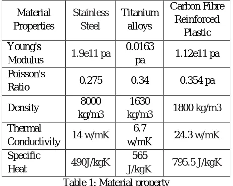
A. Material Property
Material Properties Stainless Steel Titanium alloys Carbon Fibre Reinforced Plastic Young's
Modulus 1.9e11 pa
0.0163
pa 1.12e11 pa
Poisson's
Ratio 0.275 0.34 0.354 pa
Density 8000
kg/m3
1630
kg/m3 1800 kg/m3
Thermal
Conductivity 14 w/mK
6.7
w/mK 24.3 w/mK
Specific
Heat 490J/kgK
565
[image:3.612.191.422.90.274.2]J/kgK 795.5 J/kgK
Table 1: Material property
B. Objectiveof the Work
The main objective of the current work is
1) To predict natural frequency, and harmonic effects for different blade angle (5.5, 8.5, 12.5, 16.5 Degrees) on the compressor blade.
2) To simulate the compressor blade of the different material having different blade angles for variable modes.
3) Parameter sensitivity study of Compressor blade.
4) To define natural frequency effects, harmonic effects for the compressor blade of the different blade angle profile and different material and constant acceleration of 9.81m/s2.
5) To predict frequency distribution along the compressor blade.
IV. FINITE ELEMENT METHOD
The finite element method (FEM) (its practical application often known as finite element analysis (FEA)) is a numerical technique for finding approximate solution of partial differential equation (PDE) as well as integral equation. The solution approach is based either on eliminating the differential equation completely (steady state problem), or rendering the PDE into an approximation system of ordinary differential equation, which are then numerically integrated using standard technique such as Euler’s method , Rungekutta, etc. In solving partial differential equations, the primary challenge is to create an equation that approximates the equation to be studied , but is numerically stable , meaning that error in the input and intermediate calculation do not accumulate and cause the resulting output to be meaningless. There are many ways of doing this, all with advantages and disadvantage. The finite element method is a good choice for solving partial differential equation over complicated domain (like cars and oil pipelines), when domain changes (as during a solid state reaction with a moving boundary), when the desired precision varies over the entire domain, when the solution lacks smoothness.
A. Finite Element Analysis
Technology (IJRASET)
fracture.
B. Finite Element Analysis Work
FEA uses a complex system of points called nodes which make a grid called a mesh. This mesh is programmed to contain the material and structural properties which define how the structure will react to certain loading conditions. Nodes are assigned at a certain density throughout the material depending on the anticipated stress levels of a particular area. Regions which will receive large amounts of stress usually have a higher node density than those which experience little or no stress [5-6].
V. MODELING
A. The procedure for solving the problem is
1) Create the geometry.
2) Mesh the domain.
3) Set the material properties and boundary conditions.
4) Obtaining the solution
Analysis Type- Modal and Harmonic analysis (Coupled field)
B. Preprocessing
Preprocessing include CAD model, meshing and defining boundary conditions.
1) CAD Model:
Base width 26
Blade height from base 65
Blade height 180
Blade angle 5.5⁰,12.5⁰
[image:4.612.128.485.430.677.2]Blade thickness 15
Table 2: Dimension of Compressor blade (All Dimension in mm & Degrees)
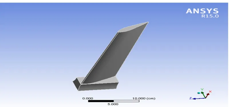
CATIA Model of Compressor blade with different angle.
Technology (IJRASET)
[image:5.612.114.503.266.404.2]Figure 5.2 CAD Model of Compressor blade with 8.5⁰ angle
Figure 5.3 CAD Model of Compressor blade with 12.5⁰ angle
Figure 5.4 CAD Model of Compressor blade with 16.5⁰ angle
VI. ANALYTICAL RESULT
[image:5.612.107.507.426.614.2]Technology (IJRASET)
Modes Experimental Results Simulation Results
3 628 569
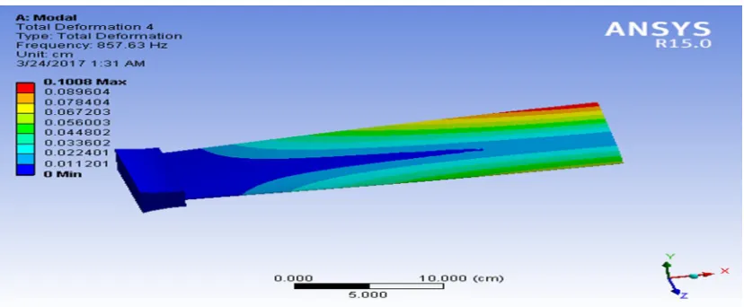
4 616 857.63
5 602 1534.4
6 585 2550.7
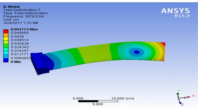
7 579 2678.5
[image:6.612.36.584.73.519.2]8 570 2904.4
[image:6.612.119.498.352.507.2]Table 3: Validation Result of Compressor blade with Different Modes and Frequency.
[image:6.612.100.514.529.700.2]Figure 6.1 Frequency and modes Distributions along the Compressor blade
Figure 6.2 Third mode Frequency of Compressor blade of Stainless Steel.
Technology (IJRASET)
[image:7.612.104.509.257.467.2]Figure 6.4 Fifth mode Frequency of Compressor blade of Stainless Steel.
Figure 6.5 Sixth mode Frequency of Compressor blade of Stainless Steel.
[image:7.612.115.500.490.700.2]Technology (IJRASET)
Figure 6.7 Eighth mode Frequency of Compressor blade of Stainless Steel.
Comparison of frequency with different material
Mode
Natural Frequency (Hz)
Stainless steel Titanium
alloys Carbon fiber reinforced plastic 5.5⁰ angle 12.5⁰ angle 5.5⁰ angle 12.5 ⁰ angl e 5.5⁰ angle 12.5⁰ angle
1 90.92 85.34 4.99 3.34 171.2 158.3
2
487.7 491.5 26.73 29.1
2
915.3
1 922.4
3
569 579 31.21 50.5
6
1068.
8 1096
4
857.6 883 45.88 79.3
5
1562.
7 1690
5
1534 1680 84.01 123.
5
2875.
4 2987
6
2550 2768 136.6 178.
3
4655.
6 4893
7
2678 2987 146.1 198.
4
4996.
3 5389
8
2904 3087 158.4 234.
2
5420.
5 6567
[image:8.612.183.430.368.697.2]Technology (IJRASET)
Mode
Natural Frequency (Hz) Stainless steel
Titanium alloys Carbon fiber
reinforced plastic
8.5⁰
angle
16.5⁰
angle
8.5⁰
angle
16.5⁰
angle
8.5⁰
angle
16.5⁰
angle
1 98.46 128.3 0.0007 4.57 185.3 198.3
2 485.5 578.3 0.0008 6.34 911.18 982.4
3 615.5 784.4 0.006 13.46 1154.4 1296
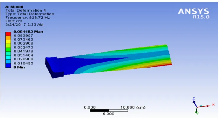
4 928.7 1034 0.0015 43.35 1691.8 1790
5 1658 1856 0.0028 63.5 3109.6 3287.3
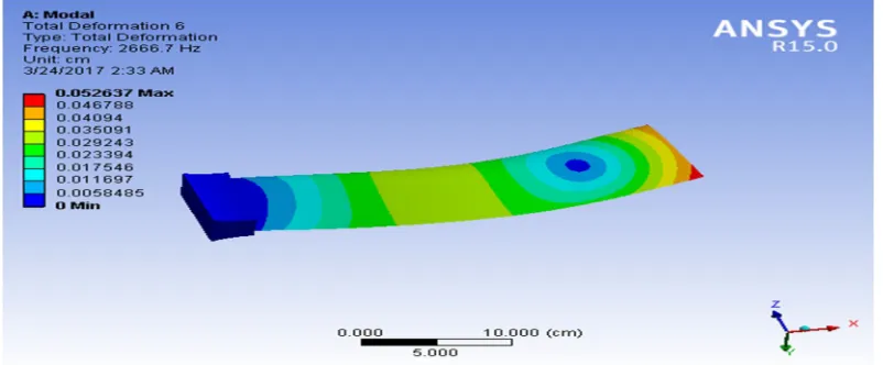
6 2666 2856 0.0046 78.3 4975.3 4393.3
7
2770 3098 0.0046 98.45 5054.7 5889.4
8
[image:9.612.121.491.310.510.2]3146 3234 0.0054 124.2 5877.4 6865.2
Table 5: Natural Frequency of Compressor blade with Different blade angles and materials.
[image:9.612.123.489.533.701.2]Figure 6.8 Fourth mode Frequency of Compressor blade of 8 Degree Blade angle of stainless steel.
Technology (IJRASET)
Figure 6.10 Sixth mode Frequency of Compressor blade of 8 Degree Blade angle of stainless steel.
VII. GRAPHICAL COMPARISION
Figure 7.11 Comparison of Natural Frequency and modes Distributions along the Compressor blade of with Different Material
Figure 7.12 Comparison of Natural Frequency and modes Distributions along the Compressor blade of with Different Material
Technology (IJRASET)
VIII. RESULT AND CONCLUSION
The current analysis has presented a study of natural frequency characteristics of a compressor blade of different profiles. Coupled-field analysis was carried out on structural steel, carbon fiber reinforced plastic and titanium alloys system. The effect of blade angle profiles of the compressor blade with angle 5.50 ,80 ,12.50 ,16.50 on the natural frequency and modes of different materials effects distribution along the compressor blade was studied. From the analysis of the results, following conclusions can be drawn.
REFERENCES
[1] C.H. Tao, P.D. Zhong and R.Z. Li: Failure Analysis and Prevention for Rotor in Aero engine (National Defenses Industry Press, China 2000), pp.102-163. (In Chinese)
[2] V.N. Shlyannikov, B.V. Iltchenko and N.V. Stepanov: Engineer Failure Analysis, Vol. 8 (2001) No.5, pp.461- 475.
[3] R. Herry, G. Feraris and Sub structuring: Transcations of ASME Journal of Engineer-ing for Gas Turbine and Power, Vol. 106 (1984) No.1, pp.2-10. [4] J. Zhang, W.L. Wang and X.J. Chen: Acta Mechanica Solida Sinica (English Edition), Vol. 1 (1988) No.1, pp.6170.