a strong need of safe braking system having low cost value. In our project we have designed and manufactured a mechanically operated ABS system which is having cost value of Rs.1500-2000. The smart braking system having such a low cost value will be affordable to customers also.
Keywords— Mechanically operated ABS System
I. INTRODUCTION
Concept of SMART BRAKING is specially designed for Two-wheeler vehicles, in which both front and rear brakes are controlled by single lever. The pedal force is distributed in 40:60 ratio to uniformly control both the brakes which results in skid-free operation of vehicle. Skidding results when friction in brakes become more than the friction between tyre and road surface. That means that the wheel gets locked and start skidding on the road surface. Less force leads to poor braking and more force leads to skidding. So to avoid the skidding of vehicle, the braking force should remain in limit.
BRAKE FAILURE INDICATOR- In this case sensors are fitted in the brake shoes at certain distance from shoe surface, when shoe get wear out sensor detect it and gives signal to operator.
II. OVERVIEW OF SMARTBRAKINGSYSTEM
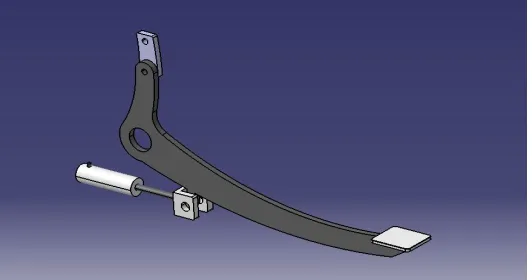
[image:2.612.174.440.467.607.2]As shown in fig. 1, smart braking system consists of cylinder piston arrangement connected to the rear brake pedal. when we press the pedal for braking, rear brake as well as front brake get operated by this arrangement. We are connecting a fluid line to this cylinder piston arrangement which is used to operate front brake. As we press the pedal the movement causes displacement of piston. The cylinder piston arrangement is double acting, as piston gets displaced the brake fluid in the cylinder is compressed. This pressurised fluid passes through the fluid line to the front brakes. We chose the cylinder as per our requirement of having 40 percent of total braking force to the front brake and 60 percent to the rear brake.
Fig no. 1- Assembly of smart braking system.
A. Cylinder Piston Arrangement
Fig. 2. Cylinder Piston
B.Foot Pedal
[image:3.612.206.416.283.447.2]Foot pedal is used for the operating both brakes. Brake lever is made up of stainless steel. It is used to operate both brake at the same time by pressing, it operates by a solid link as well as it incorporates displacement of piston into cylinder to pressurize brake oil, by which front brake is operated.
Fig. 3. Foot Pedal
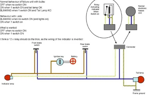
C. Brake Failure Indicator
Due to continuous use the brake pads get wear out after some time. Brake failure indicator is used to warn the driver when the vehicle brake pads crosses the safe limit of wearing out. When the pads wear out beyond safe limit marked on brake pad, sensor senses it and completes the circuit. After completion of the circuit the indicator fixed near speedometer shows signal to the driver. The prior detection of brake failure avoids accidents.
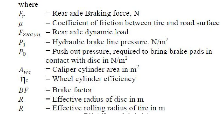
[image:3.612.192.429.534.688.2]Table 1. Notations for brake design Weight of bike with rider = 125+ 75 = 200kg
On front wheel = 29% weight of total = 58 kg On rear wheel = 71% weight of total = 142kg
Assume condition
Velocity of bike 80 kmph Time of braking 5 seconds
Let’s calculate acceleration
A= V2- V1/(T2-T1)
V1 = initial velocity = 80 kmph
V2 = final velocity = 0 kmph
T1 = initial time = 0 sec T2 = final time = 5 sec A = (0 – 80)/ (5 – 0) Acceleration = -4.44m/s2
Here negative sign indicates declaration Braking force at rear wheel = Fr
Fr = ma Fr= 142 X 4.44 Fr = 630.48 N
Braking force at front wheel = Ff Ff = m X a
Ff= 58 X 4.44 Ff= 257.52N
Fig. Brake paddle
Here we apply 31.8 N on brake pedal, and distance of brake pedal is 200mm So moment generated at pivot is,
M = 200 X 31.8 M = 6360 N-mm
This moment transmitted to other side of fulcrum and force where magnified. 6360 = 70 X F
F = 90.85 N
Force applied to front brake (disc) Force applied at lever 12N
Area of master cylinder = 50.26 mm2 Pressure in fluid pipe line
P = F/A P = 12/50.26 P = 0.238 N/mm2
Further this pressure amplify in caliper Area of piston = 3.14/4 X 252
Area of piston in caliper = 490.87 mm2 Force applied by piston
P = F/A
0.238 = F/490.87 F = 0.238 X 490.87 F = 116.82 N
This force approximately half of required force to stop front wheel Hence it stops front wheel more quickly than rear wheel.
E. Actual Design of Cylinder
Hydraulic cylinder 16*150(1.15 Mpa) Applied force on brake pedal=32N
Area of cylinder=201.06 mm2( Cal- 3.14/4×d2 where d= 16 mm) Pressure in fluid line=F/A
=32/201.06 =0.16N/mm2
This pressure is less than that of which we calculate first in original fluid line pressure was 0.238 N/mm2 So now pressure applied to disc caliper is
And then increased length of link from 70 to 120mm hence Force transmitting also increased
So momentum generated at pivot is, M=200×31.18
M=6360N-mm
This momentum transmitted to other side of fulcrum and force where magnified Torque=120×32
Torque=3840N-mm
Now distance of cam in drum brake to its pivot 12.5 mm Force= Torque/Distance
Force=3840/12.5 Force=304.6 N
Rear brake force 304.6 N
III.MATERIALSELECTIONFOR SMART BRAKING SYSTEM
The material used for cylinder piston arrangement is stainless steel. Steel is the material having high strength as well as high weldability. The link joining the rear brake pedal and piston rod is also made up of stainless steel. The fluid line passing through the cylinder to the front brake is made up of thermoplastic. The fluid line material does not affect on the properties of brake fluid. Sensor used is made up of aluminum.
IV.MACHININGPROCESSFORSMARTBRAKINGSYSTEM
Smart braking system consists of cylinder piston arrangement stainless steel material. This arrangement is connected to rear brake pedal by means of fixed link. The link has two ends one is joined to the pedal screw and nut arrangement for which the hole is drilled on pedal. Another end is attached to the piston by oxy-acetylene welding. Another part of our smart braking system is brake failure indicator. In brake failure indicator we are fixing a non-contact type sensor. For fixing the sensor the brake pad is drilled with a drill bit of size equal to size of sensor. For fixing indicator near speedometer we used screws. Screws are fixed in the drilled holes.
V. WORKINGANDDATAANALYSIS
incorporates movement of one of brake pad towards disc. The motion of vehicle is controlled by converting the speed of vehicle into the heat energy generated by friction. On the other hand, when we push the foot lever the mechanical linkage connected to it get linear motion which causes movement of cam placed in rear drum brakes. When cam starts moving its shape causes movement of trailing and leading shoes which rubs against rotor and causes controlling of vehicle speed.
Our mechanically operated anti-lock braking system is based on the principle of force distribution. For that purpose we are extending foot lever vertically which gets angular displacement directly proportional to the foot lever movement. By the extension of lever we can vary the braking force provided to rear drum brake and by controlling the motion of piston of master cylinder placed below the foot lever.
VI.CONCLUSION
Mechanically operated anti-lock braking system simplifies the braking system as well as avoids skidding of vehicle while driving. By consideration of cost factor and its effectiveness it is a affordable and safe replacement for the traditional braking system. Brake failure indicator effectively alerts driver when there are the chances of wear out of brake pads beyond safe limit.
REFERENCES
[1] E. Esmailzadeh, A. Goodarzi and M. Behmadi, “Optimized Braking Force Distribution during a Braking-in- Turn Maneuver for Articulated Vehicles”, International Journal of Automotive Engineering, Vol. 1, Number 1, January 2011,pp. 56-61.
[2] M. S. Manikandan, K. V. Nithish Kumar, M. Krishnamoorthi, and V. Ganesh, “Control of Braking Force under Loaded and Empty Conditions on Two Wheeler”, World Academy of Science, Engineering and Technology, International Journal of Mechanical, Aerospace, Industrial, Mechatronic and Manufacturing Engineering,7(9),2013,International Scholarly and Scientific Research & Innovation 7(9),2013, pp. 721-727.
[3] “Braking Force and Its Control”, Chapter 2, pp. 36-49. [4] “Design of Motorcycle Disc Brake", Chapter 3, pp. 51-52.
[5] Jost Gail, Joachim Funke, Patrick Seiniger, and Ulrich Westerkamp “Anti-lock braking and vehicle stability control for motorcycles-why or why not?”, Gail, pp. 1-15.
[6] A. A. Aly, El-Shafei Zeidan, A. Hamed, F. Salem “An Antilock-Braking Systems (ABS) Control: A Technical Review”, Intelligent Control and Automation, 2011, Vol. 2, pp.186-195.