Technology (IJRASET)
A Simulation Model for Reactive Power
Compensation
Ashutosh Barua
Amity University Madhya Pradesh
Abstract: In the modern power system the reactive power compensation is one of the main issues, thus we need to work on the efficient methods by which Var compensation can be done easily and we can optimize the modern power system. Var control technique can provides appropriate placement of compensation devices by which a desirable voltage profile can be achieved and at the same time minimizing the power losses in the system. In this paper the hybrid systems is used for dual compensation of reactive power and DC magnetic bias in distribution systems, and it results in desired real power in the system.
Key Words: Reactive Power, IGBT, FACTS devices
I. INTRODUCTION
Reactive power control has been looked at as an important issue in distribution systems for many reasons [4].First, the need for most efficient operation of power systems has increased with the price of fuel. For a given distribution of power, the losses in the system can be reduced by minimizing the flow of reactive power. Second, the extension of the power network specially in the distribution level, has been curtailed in general by high interest rates, and in particular cases by right-of-way. In many cases power transmitted through older networks has been increased, requiring the application of reactive power control measures to restore stability margins. Third, voltage is considered as one of the most important parameters of the quality of power supply. Its deviation from the normal value may be harmful and expensive. Reactive power control is an essential tool in maintaining the quality of supply. An extensive amount of research has appeared dealing with reactive power control in power systems. In general, most of this research falls within the following subgroups of the Var/voltage control problems. The reactive power planning and operation is an optimization problem of nonlinear, non-smooth, and non-continuous function. It is one of the most complex problems of power systems because it is requires the simultaneous minimization of real power losses to reduce the operating cost and improve the voltage profile, and the cost of additional reactive power sources [5].Capacitors are widely installed on Distribution systems for reactive power compensation to improve the voltage profile and to reduce power and energy losses in the system. The extent of these benefits depends upon how the capacitors are placed in the network and how effective the control schemes designed for them are. The general capacitor placement problem consists of determining the optimal number location, types, and sizes of new and existing capacitors and their control schemes, such that objective function (savings associated with the capacitor placement minus the cost of capacitors )is maximized while the load and operation constraints (voltage magnitude, current flow rating, etc)at different load levels are satisfied.[6]
III. REACTIVE POWER COMPENSATION PRINCIPLES
In a linear circuit, the reactive power is defined as the ac component of the instantaneous power, with a frequency equal to 100/120 Hz in a 50- or 60-Hz system. The reactive power generated by the ac power source is stored in a capacitor or a reactor during a quarter of a cycle, and in the next quarter cycle is sent back to the power source. In other words, the reactive power oscillates between the ac source and the capacitor or reactor, and also between them, at a frequency equals to two times the rated value (50 or 60 Hz). For this reason it can be compensated using Var generators, avoiding its circulation between the load (inductive or capacitive) and the source, and therefore improving voltage stability of the power system. Reactive power compensation can be implemented with Var generators connected in parallel or in series.
The principles of both shunt and series reactive power compensation alternatives are described below:
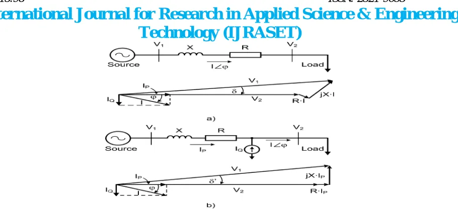
A. Shunt Compensation
Technology (IJRASET)
Fig. 1. Principles of shunt compensation in a radial ac system. (a) Without reactive compensation. (b) Shunt compensation with a current source.
If the load needs leading compensation, then an inductor would be required. Also, a current source or a voltage source can be used for inductive shunt compensation. The main advantage of using voltage- or current-source Var genera- tors (instead of inductors or capacitors) is that the reactive power generated is independent of the voltage at the point of connection.
B. Series Compensation
Var compensation can also be of the series type. Typical series compensation systems use capacitors to decrease the equivalent reactance of a power line at rated frequency. The connection of a series capacitor generates reactive power that, in a self-regulated manner, balances a fraction of the line’s transfer reactance. The result is improved functionality of the power transmission system through:
1) increased angular stability of the power corridor;
2) improved voltage stability of the corridor;
3) Optimized power sharing between parallel circuits.
[image:4.612.88.543.35.244.2] [image:4.612.199.426.450.611.2]As was already mentioned, series compensation with capacitors is the most common strategy. Series capacitors are installed in series with a transmission line as shown in Fig. 3, which means that all the equipment must be installed on a platform that is fully insulated for the system voltage (both the terminals are at the line voltage). On this platform, the main capacitor is located together with overvoltage protection circuits. The overvoltage protection is a key design factor as the capacitor bank has to withstand the throughput fault current, even at a severe nearby fault. The primary overvoltage protection typically involves nonlinear metal–oxide varistors, a spark gap, and a fast bypass switch. Secondary protection is achieved with ground mounted electronics acting on signals from optical current transducers in the high-voltage circuit.
Independent of the source type or system configuration, different requirements have to be taken into consideration for a successful operation of Var generators. Some of these requirements are simplicity, controllability, dynamics, cost, reliability, and harmonic distortion. The following sections describe different solutions used for Var generation with their associated principles of operation and compensation characteristics. [7]
IV.STRUCTURE, PRINCIPLE AND SIMULATION MODEL OF THE DC BIAS COMPENSATION DEVICE THAT COMPATIBLE WITH REACTIVE POWER COMPENSATION
A. DC magnetic bias compensation and working principleof the topology that compatibility of reactive power compensation.
[image:5.612.121.463.306.391.2]Fig. 2. hybrid structure composed of inverter and chopper
Fig.2 is a hybrid structure composed of inverter and chopper. The left connects to the grid, to produce the required reactive power. While the right side of the chopper device, connects the transformer neutral point to compensate DC magnetic bias. Capacitors in parallel can stabilize the DC side voltage. The two LC filter groups in the right can form a second order filter, which can suppress switching components producing high-order harmonic into the transformer, capacitor C is used to support the voltage.
ASVG is composed of the IGBT, freewheeling diode and capacitor C of voltage supporting.[4]
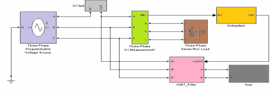
V. SIMULATION MODEL AND RESULTS
Simulation is done for reactive power compensation. A hybrid system modelling is done by combining the chopper circuit to realize the dual compensation of reactive power and DC magnetic bias, we use the Simulink to run the simulation, its models and results are as follows:
[image:5.612.70.533.555.707.2]Technology (IJRASET)
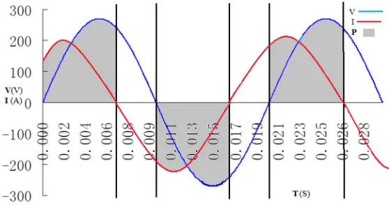
Fig. 4.Graph of phase voltage, current and power without compensation of reactive power
Fig. 5.Graph of phase voltage, current and power with reactive power compensation
VI. CONCLUSION
The results shows that, when we use the compensation device, it can balance the voltage and current to normal levels, as we know that there is reactive power due to capacitive and inductive elements in the grid which can make the current and voltage phase difference, due to which the real power in the system reduces from the ideal level, but after we introduce the compensation device, the current and voltage waveforms have same phase, and due to this compensation effect, power in the system achieves to the desired value with stable voltage.
REFERENCES
[1] Akwukwaegbu I. O, Okwe Gerald Ibe “Concepts of Reactive Power Control and Voltage Stability Methods in Power System Network” IOSR Journal of Computer Engineering (IOSR-JCE) e-ISSN: 2278-0661, p- ISSN: 2278-8727Volume 11, Issue 2 (May. - Jun. 2013), PP 15-25
[2] J.F. Aldrich & H.H. Happ, “Benefits of voltage scheduling in power systems”, IEEE Transactions on Power Apparatus and Systems, PAS, 99 (5), 1980, 1701- 1712.
[3] “Final Report on the August 14, 2003 Blackout in the United States and Canada: Causes and Recommendations,” U.S.-Canada Power System Outage Task Force, April 5, 2004.