BY
Hsu Tsi Pan
In Partial F9%%filhent of the Requireaents f o x the Degree of Easter sf Science in Aheronautical Engineering
C a l i f o r n i a Institute of? T e c M s l o a Pasadena, California
me author wishes t o express M s gratitude ts Drso Theodore vgan Kamm znd X,E, Sechler for the suggestLon of this resesrch s u b j e c t aad their helpful cri%ieism during $he course sf' the Grateful acknowledgenent is also nsde to Dr* HeS, Taien fox his cousstm% help during the
H Y
8
m 0=*
En 5 R M B 4 0 P e %% 0 w w w+
I-' I-' I :=- I-' e\4 llbs
63 mIn the conat-wction sf modem ~ e t a l a i r p l a n e s t h e r e are slzmy l o c a t i o n s where a. more o r l e s s coneentaaated l a a d
i s % r m s f e r r e d t o a l a r g e a r e a sf maderisl* m e r e f o r e the desim-engineer i s f aaequenztly confronted with the problem of "shear lag"'. This groblem can be Lreeted in a fefv s u p l e cases by the mathematical t h e o q ~ of a s t i c i t y , e s p e c i a l l y
by Aiw" s t r e s s f ~ n ~ t i o n s ~ but i n meny o t h e r c a s e s , i n o r d e r
t t s avoid m,athceraa%ica1 ~ o q l e x i t f e s , c e r t a i n a s s m p t l o n a must Be made which w i l l simplify the a n a l y t i c a l solutia~lm o f the problem* m e s e a s s m p t i s n s u s u e l l y do n o t agree with the actu~!$, eonditioas t h e r e f o r e the r e s u l % s z r e not ademate* the p h o t o e l a s t i c method, ho~rever, the r e s u l t s obtained
1) Propagation o f light
in
isotropic md c ~ a t a l l i n e media*Optical wave theories describe light a s a traaasverse wave
motisng The wave front of
an
optical disturbmce a d ~ m c i n gtbrou& a trmsparent m e d i m i s considered to be p l m e in, the aeigfrrborkiooa o f my point in the medim,
In
an isotropic medim there is only one wave velocit;y and it is the s m eregardless BP
the
direction o f trayel sf the Sight*In a
e w s t a l l i n e a e d i m ,however there are, x7~ave v e l o c i t i e s for eaeZ~, wave n o m a l
a&
these bsjro velocities zlre d i f f e r e n tfor
m v e nomaabs through %he point, in different direc%ions.
m i s is the phenomenon a f double refractdoe, Tkherefore there will be two parallel wase f r o n t s f o r each wave n o m a , f i r t h e r e allore, each of the waves is plme-polarized; t b t is, a%e vi- Brztioa eorrespsnding t o each of the waves Lies in a plane, and the t w o waves are p e r p e n d i c u a r
to
e ~ c h other a d to the weve namal, If light of wa~e-lengthh
is passed e t n o m aincidence through EL c q s t a l l i n e p l a t e o f thicbess d, the %xvo
resulting p l a n e = p o l z r i a e d wzbTes mdesgo phase retardations,
A, and A,
,
with respect Lo an mimpeded rvave, given byv~here
n
is &he index of refraction of the rr~edfzzrvli ou%sfde the p l a b ean?84,
m d A, are measured in acadfana, Their r e l a -2 ) The photoela.stic effect;,
I t was discovered kyy Bre~dster, t h a t a h s s t a l l tr8ps- m ~ t e r i a l s , ~ak.,en s t r e s s e d , become optie~lly doubly ref reo"eing, a d l a t e r Bfiaxvell obsemed t h a t $233 relzztican be-
%%reen s t r e s s and doable r e f r s c t i a n i s s b i l a r t o the s t r e s s
a d s t r a i n r e l a t i o n , Therefore, we may write, by malow ~ v i t h the s t r e s s end s t r a i n r e l a t i o n :
in which Ciaand C,are %he s t r e s s - o p t f c a e s e f f i c i e n k s , P m d $ a r e p r i n c i p a l s t r e s s e s respectively, Ro is the o r i g i n a l
o p t i c a l index o f the uns%ressed m e t e r i a l , Bence, i f we measure the absolute phase r e t a r d a t i o n s d l and 4, we can c a l c u l a t e the p r i n c i p a l s t r e s s e s P md
Q,
a d if we measure the r e l a - t i v e phase r e t a r d a t i o n Awe
c m calculate the griacipalstress d i f f e r e n c e P-&, f o r f r o a tlxe eqs, 2 a d 3 w e have
i n ufhich 6: 2 C1-C2 i s the r e l a t i v e s t r e s s optical c o e f f i c i e n t ,
If
we
deternine %he d i r e c t i o n s o f the p r i n c i p a l axis of %hee t q , we shall have the d i r e c t i o n s o f the prin-
3 ) Test procedure:
a) J-pp 3x8 %us,
m e apparatus o e i n ~ i s t s of a l i g h t sonrea, a p o l a s h e r , and
ana
w a l y z e r , w i t h t h e i r respective quarter--$am p l a t e s , acmera, and st loading f %me, 'd"no s p h e r i c a l m i r r o r s and eon- densing l e n s e s a r e enployed t o give a large be= o f li@t
tlarou* the glodek, The t w o polaroids z r e mm%ed in indivi- dual a t ~ a d a f r e e to r o t a t e 180 degrees as r e w i r e d i n deter-
mining the i s o c l i n i c l i n e s , Attached t o each poleroid i s the qun~%er-xsve p l a t e inclined a t 45 degrees t o the axis of the p o l a r o i d , m e s e q u ~ s t e r - ~ a v e p l a t e s a r e quickly de- %achabke as the procedure demands* The e m e r a i s made of a ~ ~ a o & e w box attached w i t h orainary c a e r a shutter md p l a t e
' holder m d e t o s l i d e on a r a i l f o r focusing,
b) Podel
The materia$, use6 f o r m&ing the model is B&e$ite BT61893 mnnufactured by the B a e P i t e Corporation, 247 Perk Avenue,
We15f Y o r k City, h o n g the desf r p b l e p r o p e r t i e s 0%" t h i s aatsrial
zre: 1, l i n e a r stress-strain relation, 2* hi& moduLus of elasticity, 3* p h y s i c a l and optical homsgened%r, 4. &i&
Lrasparancy, The physical p r o p e r t i e s o f t h i s B d c e l P t e is given by GeHe Lee a d C,W, Amstrong ( ~ e f s, 66, P Q I R B S ~ B 380d~-
l u s + 615 pornads p e r square in* Poissons R s t i o Z 0,373*
Concerning t h e B h i c b e s s o f %he model, it is m d e r s t o o d that
i n a p l a t e ; hovfever, %be s m a l l e r the t h i c k n e s s of the plate i n sompariaon w i t h a r e p r e a e n t a t l s e P i n e a r dimension
in
theplane o f %he p l a t e , the c l o a e r i s the s i m % l a r i t y r T t is also %me t h s t t h e l a r g e r t h e thickness o f tke p l a t e , i n c o m p a r i s o ~ w i a a r e p r e s e n t a t i v e f i n e z r dimension i n t h e p l m e o f the
p l a t e , t h e c l o s e r does the s t r e s s d i s t r i b u t i o n approach a s t a t e 0% plene s t r a i a a 1% is only l a e n the thickness and s t h e r d h e n s f o n s o f
$he
p l a t e are of the a m e o r d e r o f na-i- tude t h a t a tiyo-dimensional s t a t e o f the stress is not, i n general, r e a l i z e d , I n t h e present case the dimension of theplate
1 8 3 % 5 thethickness
o f the plate is .23 i n gThe model is machined t o t h e d e s i r e d shape znd t h e f i n i s h i n g i s accompXished by c o a t i n g the model with Ihcquer, thus s a v i ~ g
the time o f grinding znd polishing,
c) Loading,
Creeping a c t i o n i n % & e l i t e m d e r moderately high s t r e s s e s i s one o f t h e i a p o r t m t phases of the p h y s i c a l p r o p e r t i e s af the m a t e r i s l , .A thorough study o f t h e various c h r a c t e r i a -
tics of $a&elfte has
been
ca.rrie8 outat
%he
Testing Labors- Lories o f C o l w b i a U n i v e r s i t y , pad %% was pointed o u t A e G e~ g $ l & i m ( ~ e f t3188% Sin a specimen
-&
i n c h i n t h i c b e ~ s ~ s t r e s s e s correspondingto
a f r i n g e o f eleventh o r d e r can be used s a f e l y * I n the p r e s e n t ease, t h e model i s loaded i n two d i f f e r e n tmags: v p e 1: T4ne lo2a i s a p p l i e d t o the s t i f f e n e r a% t h e
Type 11: m e h a d %s a p p l i e d t o the s t i f f e n e r a t the t o p
md absor%ed a s a d i s t r i b u t e 8 l o a d a,crosa the %.aebs oarnl~, me load a p p l i e d i n each type o f loading i s 2800 Ibs, corresponding approxima,tely t o a maximm fringe order o f elevene
The l o a d i n g f s m e i n which the model is losded c o n s i s t s of a machined f l a t as a base, e,method o f applying the l o a d , pnd a mne8xs o f d e t e m f n f n g the l o s d , The loading % e m is
c a l i b r a t e d , giving d i a l reading against load. Some diffi-
culty was f o m d v:i$ka the loading fr,me, therefore, i f f u r - ther e,qerimes%ts e r e L o be made, a loading mach2srre should
be desime8,
d ) ITetwork o f Reference,
I n o r d e r Lo t r c m s f e r the observed isochronatic snd i s o - clinic Pines t o %he c % s a ~ ~ i n g board the photogsapkic method i s used*
I ) Isochromatic l i n e s ,
%sochromatie l i n e s by d e f i n i t i o n are t h e shear contour
lines; Lee, Ifnes along ~vhich %he m a h m shearing s%resa i s F constan$, The photsgrzrhs o f t h e isoebromatic l i n e s are %?Ben by using the circularly polarized l i g h t * The Xi@%
source i s a monschrormsatic 6 0 - w a t f l o d i m Lab-ereB, The mono-
2) I s o c l i n i c l i n e s
The i s o c l i n i c l i n e s l i n e s fay d e f i n i t i o n a r e t h e l i n e s along 1~hic9.n t h e d i r e c % i o n s o f t h e p r i n c i p a l s t r e s s e s e r e con-
s L a # t e Previously ( ~ e f , I), t h e s e Pines have been recorded by negns of mono~hrian8%/@ X i a t e Then the i s o c l i n i c l i n e s can only be d e t e c t e d 'by conparing L't:vo p l a t e s , one %&en w i t h
p l a n e - p s l s r i z e d l i g h t end amother %?_&:en w i t h C I T C U ~ E F X ~ PO-
l a r i z e d Lighto f n o r d e r t o e l i m i n a t e t h i s r a t h e r t e d i o u s
work, t h e p r e s e n t a u t h o r used plane-polarized ~ v h i l e Pigkt
snd pmchromatic photogr8,phic p l a t e s , I n thfz: case, t h e iso-
chromatic l i n e s w i l l appesr a s bands o f d i f f e r e n t c o l o r but of zpprss=irastefy t h e sBme i a t e n s i Q y , t h e r e f o r e they w i l l n o t be r e g i s t e r e d on t h e pknotogr~phic p l a t e when developedo
Thus t h e record i s n o t only e3sieZ t o use b u t a l s o more ES-
c u r s t e . Bowever igl u s i n g l ~ i h i t e light, because of i t s s t s o n g
i n t e n s i t y t h e model ail$ be heated, The t e s t p e r f o m e d
G,NB Lee and C,W, Amstrong ( ~ e f e 6 ) on B a k e l i t e BY63893
i n d i c a t e s t h a t t h e r e l a t i o n s h i p bet~speen t h e f r i n g e o r d e r ,ad %he s t r e s s a r e l i n e e r over %he temperature range from
26" "& x ~ o O F , , however &he e f f e c t of creep of the m e t e r i a l i s n o t i c e d a% the t e n p e r a t u r e 9 6 : l 0 6 " ~ ~
In
oraear %o 2 v ~ P d %his undesirt3ibabe e f f e c t a water ee%X made 0% g l a a s i s placed bekg~een t h e l i g h t source 8xd t&ie speciaen, Gonplete s e r i e sof i s o c l i n i c p i c t u r e s are taken from zero t o 96 degrees
in
18 degree i n t e r n e l a Q r o t a t i o n o f %be p o l a r o f d s and a d d i t i o n d pictures s e r e made i n t h e r m g e f r o m 70' to 80' where the
3) I s o t r o p i c Points,
A t an i s o t r o p i c p o i n t , (Ref, 4) the par8meLer sf the
i s o c l i n i c i s i n d e t e m i n e t e . Renee all i s o ~ l i n i c s pass thaaough ea-i i s o t r o p i c p o i n t 2nd "bere i s sosrae d i f f i c u l t y in c o n s t m c t - ing %he i s o x t a t i c a fa the neighbsrhsodb o f such a p o i n t , F i l ~ n ,
BGppl meZ %?euBer, anzd Van IXises b a e shos,t"pz t h a t t h e eon%i@- r a t i o n of t h e i s o t r g p i c p o i n t depends upon the nmber m d o r i e n t a t i o n o f t h e d i r e c t i o n s through the p o i n t f o r which a t m g e n t $0 the i s o c l i n i c m d e s an mgle w i t h the a9 axis e q u d
t o t h e p a r m e t e r o f t h e i s o c l i n i c e There a r e one, $SV:JJ.~ o r t h r e e such a s p p t o t i c d i r e c t i o n s i n t3.e cases which occur m o s t often, These types, w i t h their corresponding iso-
s t a t i c s , a r e i l l u s t r a t e d i n Figs, below z
To deternine t o w~hieh type a p a r t i c u l a r i s o t r o p i c p o i n t be-
right lamd c o m e r between the f r e e edges, in each tgpe of loading, I n Figs 4 TPre l s o c l i n i c s through such a p o i n t are dram t o an enlarged scale. Gelling
J
the engle uxhichthe isoclinic through
0
makes 1.iith the3
axis and p l a t t i n ga graph for which the parameter
#
of the isoclinic i s the abscissa and i s the ordinate. B line AB on this d i s g r a meets the CD e u m e at a arnmber o f p o i n t s equal t o the n m b e r4) Procedure of Cdculatisns
a ) P r i n c i p a l s t r e s s t r a j e ~ t o r i e s ~
The d i r e c t i o n a l d i s t r i b u t i o n of each sf the p r i n c i p d s t r e s s e s P and Q% may be p l o t t e d a f t e r %he i s o c l i n i c l i n e s have Been detemined; the two systems f o m i n g a n e t s a r k o f
orthogonal ~ u m e s ,
b)
Itfaxhm shearing stress Lrsd e e t o r i @ e 6Since the m s i a - e a m shessing s t r e s s a t any point a c t s a t an m g l e t o the d i r e c t i o n s o f P ~ n d Q the d i r e c t i o n a l d i s t r i b u t i o n of Tmax may be simi%arXy plotted,
c ) Separation sf the p r i ~ e i p a l s t r e s s e s * 1) Calibrztion be=,
The f r i n g e order o f %he p h o t o e l a s t i c rnsterial i s deter-
mined by applying a pure moment t o a comyarison beam* $Sr using t h e f $ e m r e fornula, t h e s t r e s s a t my distance from t h e n e u t r a l exis i s enkculated, and hence the s t r e s s deter- minstion per f r i n g e Sine i s kno~~m; i,ee:
Since 6 = p md
0 = 0
~e e q x e s s i a n f o r naaximm shearings t r e s s becsnes:
t h e s h e a r i n g s t r e a s 8% a given p o i n t d i v i d e d by t h e f r i n g e
o r d e r
n
at the s m e p o i n t , tq2c.t is,O?ej /I
Prom t h e v ~ ~ r k done by previous inves%igz%ors on the s m e
problea the A r m a ~ has been d e t e m i n e d vri%kn the a a e m a t e r i a l o f the saBe t k a i e h e s s ( !? Z O 8 2 3 i n , ) :
T$.Bia has been 1 8 t e r checked w i t h t h e case o f %he second type o f Loading6 The s h e a r i n g f o r c e a% t h e stiffener calculated by u s i n g the above value, e q u a l s 92"g%omds v~lk-nieh i s a quite
saBia5"ecloq r e s u l t compzrlng w i " c ZOO8 ponds; na it should b e 2 ) D e t e m i n a t i o n o f F-Q a t any pointg
Yfe have obtained the values of P-Q on the isocromalics z~hickr correspond t o a tint o f passage, 'hat i n the ease of a s t r a i n e d model,
we
r e q u i r e P-Q at o t h e r p o i n t s , T ~ i a a de- temined by taking p i c t u r e ssf
ieochrom8tie l i n e s of pro- g r e s s i v e lozding, Since the l o a d is inere3sed in the ratioP-& z t azg p o i n t of the p l a t e ,
3 ) Determination o f the separate s t r e s s e s .
Two nne$$lods mere used.
in
d e t e m i n i n g the sapprate s t ~ e s s e i s , For the f i r s % t n e o f loading n graphical-integrntisn methodis used nhieh %%%s been suggested by LeNeG* Biloa% [ R e f * 21, The equations used i l t l t h i s method a r e given
in
the followingfoms:
p=
a
+
j i p - a ,
c o t . 9dP
a=
@*+/[o-P)
cotI/:
JP
where is the angle through which the stress
trdectory
of P a% a point has to be r o t z t e d in o d e r t o bring it upon the iso~linic at the s m e point,m e values o f P-Q and f o r $he various points having been Somd by method described, P-Q c o t e m be calculated and p l o t t e d with respect t o The area of this diagram
between eny t w o angles
4
can
be found, tms gives / l ~ - O / cof @ J+which is equd
to
P-Po, In t h i s c a s e t h e author ha8 sta.rbed f r o m pointson
the f r e e edge md followed i ~ m a r d s the line sfP-principal stress since P is zero
on
%he free edgeg Yken P - s t r e s s is h o r n evevihere on t h e plate thea
s t r e s s i scalculated, since we h o w t h e v a l u e of P-& e v e ~ ~ h e r e on the platea, It is 8.dvissble t s integrate along both p r i n c i p d
acsuracy of the w o r k , haweyer due to the limited time the
zuthor
has only integr~ted elsag P-stress l i n e s , a,nd only a fevf points hsve been checked by integrnGion along %heQ-stress lines, the results agreeing sa%isfac%ori1y with each o t h e r ,
l a o t h e r way of obtaining the principal stresses is
by a crlculatf
on
vfhich ivas i a d i c ~ t e a first by Clark Xifsm~eetl ( ~ e f * 3 ) From $heequations
of equilibri1~~t% f o r the c?sex~hen
no
body forces a r e a c t i n g an the p l a t e , me %sa,ve:f r o % ~~kie&E vie obtain by integration,
In this case, the
6
is eclqaal $0 z e r o at t h e f r e e bcsm&%arif?~,&herefare,
our equation c m be written as~~vhere h is w i d t h of $he p l a t e * In oraer -860 find "ce sshe~aring
Prom Fig, (&)we have;
B r m Figo tb) we have :
1
-
6
t a n 4-
L y+
PJ;edEenc e we have :
- 6 - ~ j y e t n d + P = O (
4 ,
~ r o m
equations7
and9
we
have:In$egratimg
&
8~ d x grzphfcally along the X ~ n d 9
axes, 6; nnd
6 y
a t e ~ c h p o i n t can be calculated by equation (5) and knoyging t h e shearing s t r e s s&
st those points by e w a t i o n (LO) we c m f i n d the p r i n c i p a l stresses P a ~ d O, by using EEohres c i r c l eor
by the relations:The author has developed a method directly from this by which the P BE&
Q
be obtaineSe 'h.g a single integmlisn,B r o a equations(%) md ( 8 ) .rve g e t :
6 , - 6 y =
GY ( h n d - ~ ~ n d ) = - T * ~ c f f i dtheref ore, s l t b s t i t u l i n g the value o f
GY
f ram e ~ a t i o n (10) :Frog& the eqaztions ( 8 ) and ( 9 ) the follwjiring relation is obt7ined:
Therefore by integrating sleang
X
axis
onXy6
18 obtained,aad h a w i n g by the equation (11) 6y c m be fse~nd,
I?-
&
68x1 be eelculated, Sfnee I?-& i s kna'i"m f r m n the evalu-m e model uaed i n %his p r o j e c t has been investigated sufficiently %o give a coapIe%e p i c t u r e o f the s t r e s s eharac- t e r i s t i ~ a of t"ae sheet reinforced wraith a stiffener,
In
CELL-
culating the separate stresses the author finds the second method i s
more
suitable, s i n c e t h e slope o f the one cume, namely f iaY i s e a s i e r t o f i n d $hm %he angle bet~veen the slopes o f two c u m e s , namely the slope of the principal stress lines and the i s o c l i n i c s , Purthemore i n Lbe first case cot
4
is involved which is liable to give considerable error if the mgLe is inaccurately m e a s u l ~ e d ~ Ebt in thesecond case only s i n d m d c o s d are i~voLseB which would not give t m n u e h e r r o r
in
case the m g l e measured is littlePhotographs. Pertinent data is s l v e n on each
pictusc, The following p h o t o -
elastic photographs are shoim:
Pages 1
-
111, The model under progressive stages of Typs % loadrng(Isochrorn~tics),
Pages 1 V
-
Vlll, Isselinics sf the model under Type 'Iloading.Pages 9X
-
XZV.
I ~ O C ~ P O ~ R ~ ~ C and Isoc%ini@so f the model under Tme %I
RPPEWDIX '5,
C~xrve s , From t h e r e s u l t s o b t a i n d , t h e following curves & r e p l a t t e d :
F i g ? , 1 arid 1 2 Evaluation of isochromatie l i n g g f o r Type I and
T y p e I1 loading r e s p e c t i v e l y ,
F i g s , 2 and 13 T r a j e c t o r i e s o f the principal
s t r e s s e s f o r T~ype I and Type 11 l o a d i n g r e s p e c t i v e l y .
F i g s , 3 and 1 4 n
-
x/h, curves f o r T y p e I and Type 11 l o a d i n g r e s p e c t - i v e l y ,F i g s , 4 and 5 Determination of t h e i s o t r s a i e p o i n t f o r t h e Type E l o a d i n g , F i g s , 6 and 1 6 Three dirsentional d i a g r m s
of t h e p r i n c i p a l s t r e s s -& f o r Type I and I1 l o a d i n g respec t i v e l y .
F i g s , 7 and l 5 Three dimenti onal d i a g r a ~ s of t h e p r i n e f c a l s t r e s s -P f o r Type I and I1 l o a d i n g r e s p e c t i v e l y ,
F i g s , 8 and 17 Three dimsntional d i a g r a n s of the s h e a r i n g s t r e s s t;y
f o r Type I and I1 l o a d i n g r e s p e c t i v e l y ,
Figs. 9,10,11 Contour l i n e s of' t h e princlnal
THREE
D I M E N
r/ONAL
D/AGi9AM
O F
7-HE
PA//Ve/PAI'.
STREJS
8
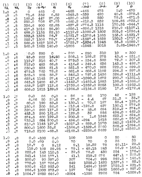
Table I,
XNTEGUTIOM ALONG P -STmSS LIMES
( $ 1 ( 2 1 ( 3 ) ( 4 ) ( 5 ) ( 6 )
Number?
#
4.4 VAL n4L
c0f)L(Pt3)
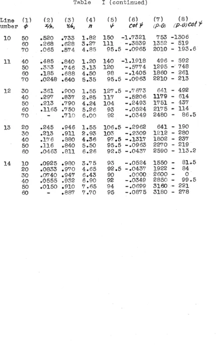
[image:54.508.42.451.49.690.2]Table I (eontlnued)
Line (1)
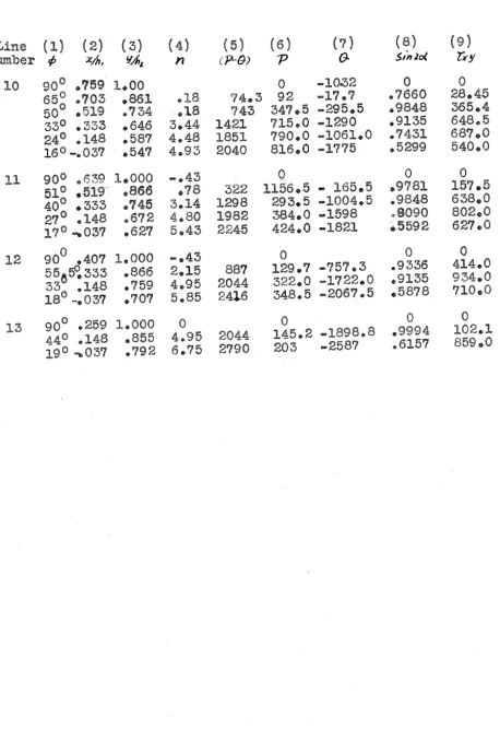
[image:55.528.36.476.25.723.2]Table I1 ( contjnued)
Line (1) ( 2 ) ( 3 )
[image:57.534.32.490.47.725.2]