© 2017, IRJET | Impact Factor value: 5.181 | ISO 9001:2008 Certified Journal
| Page 1758
Parametric Optimization of Turning Operation Using Cryogenically
Treated and Untreated Tungsten Carbide Tool Inserts
Gaurav A. Desai
1, Abhijit R. Bhagat
2, Abhay S. Naik
3, Phati P. Sawant
4, S.B.Khandekar
51,2,3,4
UG students, Mechanical Engineering, Rajendra Mane College of Engineering & Technology, Ambav,
Maharashtra, India
5
Asistant Professor, Mechanical Engineering, Rajendra Mane College of Engineering & Technology, Ambav,
Maharashtra, India
---***---Abstract -
Turning is one of the most basic machiningprocesses. In turning, a workpiece is rotated about its axis as single point cutting tool interferes with it, shearing away unwanted material and creating the desired part. Turning is influenced by many factors such as cutting speed, feed rate and depth of cut. It is required to find out the optimal parameters of machining using EN8 steel. In this paper, an attempt is made in comparison of machining parameters like speed, feed, depth of cut using Cryogenically Treated (CT) and Untreated (UT) Tungsten Carbide Tool Inserts. Taguchi method, the signal to noise ratio and the analysis of variance (ANOVA) are employed to study the performance characteristic in turning operations.
Key Words
:
Turning, EN8 steel, Cryogenically Treated, Tungsten Carbide, Tool inserts, Taguchi method, ANOVA.
1.
INTRODUCTION
2.
In the modern civilization, the manufacturing processes have increased. With the increase in the need for manufacturing processes, the metal cutting processes have forms the basis of the engineering industry. EN8 carbon steel is medium carbon and medium tensile steel with improved strength over mild steel through hardening. EN8 carbon steel can be readily machined in any conditions. It can be further surface hardened to produce components with enhanced wear resistance. IT is used for manufacturing shafts, gears, stressed pins, studs, bolts, keys etc. and due to this EN8 material is preferred in the industries. As the technology has been rapidly advancing, newer cutting tool material such as Tungsten Carbide comes into the picture. With HSS, machining EN8 is difficult and this is the reason there is a significant increase in the use of tungsten carbide. Cryogenic treatment is the process of treating workpiece to cryogenic
temperature (-190oc) in order to remove residual stresses
and improve the wear resistance. Effect of cold treatment on tungsten carbide makes it more suitable for the use. The grain size decreases and also there is a slight increase in the hardness of tungsten carbide. Cryogenic treatment can improve the wear resistance and cutting life of the machine tool. It also increases the corrosion resistance by changing the structural formula. Cryogenic hardening is a cryogenic treatment where liquid nitrogen is used to cool the material to low temperature. Research shows that this treatment is practiced on tool steels on large scale. This treatment increases the amount of martensite in the steel's crystal structure thereby increasing the surface roughness and hardness.
2. LITERATURE REVIEW
[1] A.Y.L.Yong, K.H.W Seah, M. Rehman, (2006) have described a study on the effects of cryogenic treatment of tungsten carbide. Cryogenic treatment has been acknowledged by some as means of extending the tool life of many cutting tool materials, but little known about the mechanism behind it. Thus far only a few detailed studies are conducted pertaining to the cryogenic treatment of tool steels. However, tungsten carbide cutting tools are now in common use in industries.
© 2017, IRJET | Impact Factor value: 5.181 | ISO 9001:2008 Certified Journal
| Page 1759
microstructure of HSS gets more refined and the particlesare uniformly distributed after the cryogenic treatment. Less reduction in nose radius, lower weight loss, more uniform distribution of metal particles was found
[3]M. C. Kumar, Dr. P. VijayaKumar, Dr. B. Narayan(2012) found that the Taguchi and ANOVA methods were applied to investigate the effects of cooling rate, soaking temperature, soaking time, tempering temperature and tempering time. The conclusions drawn from this work were as follows. Cryogenic soaking temperature is the most significant factor and the maximum percentage contribution of soaking temperature on the flank wear of HSS tools was 72.38 %. The best soaking temperature in the possible range was found to be -175C. The second significant factor is tempering temperature and its contribution was 10.10 % for the improvement of flank wear resistance. The best level for this factor 150 C.
[4] Nagraj Patil, ShriShail Kakkeri, (2015) found that cryogenic treatment causes morphological changes in the entire cross-section of the Tool hence the same tool life can be anticipated even after any number of re-sharpening. It is better to all type of coated tools as the coatings become futile, even after single re-sharpening of the tool. Coated carbide tools perform better than uncoated carbide tools as far as cutting forces are concerned. For average magnitudes of forces obtained with uncoated carbide tool were higher than those obtained with coated carbide tools under experimental conditions.
[5] Dr.I.Satyanarayana (2016) the cryogenic treatment process must be performed according to predefined temperature protocols, to ensure the maximum effectiveness; the cryogenic process should be carried out in a dedicated programmable cryogenic system. Cryogenic treatment can increase the cutting forces which can be reducing by use of secondary liquid nitrogen. The experimental investigation clearly explains that the different tool condition of the single point cutting tool. By this investigation cryogenic treated single point cutting HSS tool performance is better than the untreated single point HSS tool. After cryogenic treatment, the performance of cryogenically treated tool had been significantly enhanced. the particles are uniformly distributed after the cryogenic treatment.
3. MATERIAL SPECIFICATIONS
3.1 Work Material
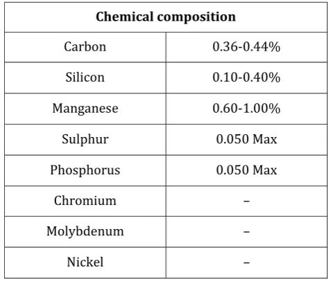
EN8 is a medium carbon steel usually supplied untreated. EN8 is a very popular grade and can be readily machined in any condition. It can be further surface hardened to produce components with enhanced wear resistance, typically in the range 50-55 HRC i.e. 469-552 BHN through induction processes. EN8 unalloyed medium carbon steel has strength levels compared to normal bright mild steel, due to thermo-mechanical rolling. The following table shows the chemical composition of the material.
[image:2.595.314.551.308.511.2]
Table 1: EN8 (080M40) Specifications
Chemical composition
Carbon 0.36-0.44%
Silicon 0.10-0.40%
Manganese 0.60-1.00%
Sulphur 0.050 Max
Phosphorus 0.050 Max
Chromium –
Molybdenum –
Nickel –
Table 2: EN8 (080M40) – mechanical properties in “R” conditions.
Max Stress
700-850 N/mm
2Yield Stress
465 N/mm
2Min
(up to
19mm LRS)
Elongation
16% Min
(12% if cold
drawn)
© 2017, IRJET | Impact Factor value: 5.181 | ISO 9001:2008 Certified Journal
| Page 1760
3.2 Cutting Tool Material [image:3.595.307.552.134.338.2]Tungsten Carbide: Tungsten carbide is a type of steel. It is comprised of mainly tungsten carbide and cobalt. The cobalt acts as a binder and improves shock resistance. Shock resistance increases with the increase in the percentage of cobalt in the mix. Tungsten carbide is known for its ability to retain an extremely sharp edge for an extended amount of time under certain cutting applications. It is also very brittle and is prone to nicking and chipping very easily. It is one of best-known materials for precision cutting. This is why tungsten carbide is mostly used in machine shops and has been selected for cutting material as hard as EN8 in this study.
Table no.3: Specifications of cutting tool
Insert style
CNMG
Insert size
432
Manufacturers grade
IC907
Coating
TiAlN
Shape
Diamond
Chip breaker
TF
Coating process
PVD
Length (mm)
12.9
Thickness (inch)
0.1874
Included angle (degree) 80
4.
EXPERIMENTS AND METHODOLOGY
The best out of many methodologies was adopted to improve the quality of product or process and experiments were carried out accordingly. The best turning parameters i.e. speed, feed, and depth of cut were selected by using Taguchi method.
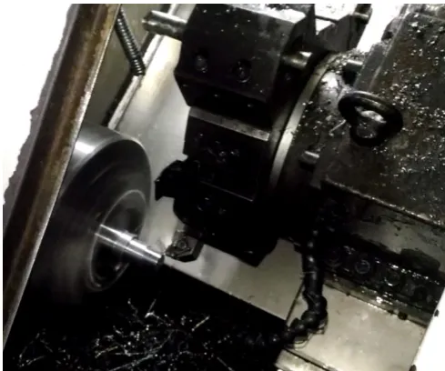
Using tungsten carbide tool inserts all the experiments were performed on CNC lathe machine. First, the machining using vegetable oil (High Cut 150) was carried out according to Taguchi design. For each experiment using an Infrared Temperature Sensor, Cutting temperature was recorded. Surface Roughness Tester was used to measure surface
roughness. Tool Maker’s Microscope was used to measure tool wear and hardness was measured using Brinell
Fig1: CNC machining
Hardness Tester. The results obtained were analyzed using ANOVA and analysis of the design of experiment to find optimum machining parameters for both UT and CT machining.
4.1 Design of Experiments (DOE)
The choice of experiments to be performed should be done in a most efficient way. DOE helps in doing so. In process development, the Design of experiment is the most powerful statistical technique and is widely used.
Table No. 4: Machining parameters and levels
Sr. no
Factor
Levels
1
2
3
1
Speed
(RPM)
1200
1400
1600
2
Feed
(mm/rev)
0.1
0.12
01.5
3
Depth of
cut (mm)
0.5
1
1.5
© 2017, IRJET | Impact Factor value: 5.181 | ISO 9001:2008 Certified Journal
| Page 1761
best possible results can be obtained. The experimentaldesigner selects the factors or parameters and defines the problem in order to perform DOE. In Minitab 17 according to L9 orthogonal array, the experiments were designed. A 33
Taguchi factorial design was obtained for machining with vegetable oil (HIghCut150) It contains 3 factors (Speed, feed, and depth of cut) each at 3 different levels
Fig2: CNC machined EN8 components.
Material removal rate (MRR) which is the input parameter can also be calculated by calculating the difference between the final weights (after machining) of the sample and initial weight (before machining) of the sample. This is one of the process parameter in this study i.e. the feed.
Tool wear rate (TWR) was calculated by finding the difference between the final length (after machining) of the tool and initial length (before machining) of the tool. In this study tool wear for all the tools used in the experimentation was calculated and its analyses for the best result was made.Tool Maker’s Microscope was used to measure tool wear .
4.2 Taguchi Method
The Taguchi method is adopted to study the effects of all the parameters with a minimum possible number of experiments. An orthogonal array is chosen and set of experiments are designed and are performed accordingly. For more accurate analysis of the effect of the machining
parameters signal to noise ratios are computed. The category the larger-to-the-better was used to calculate S/N ratio for tool wear and surface roughness. The following equation is used.
S / N = -10log10 (
)
Implementation of traditional experimental design methods is very tedious and difficult given the fact that it requires a large number of experiments by increasing the process parameters. To reduce the number of tests, a particular design of orthogonal arrays i.e. L9, L16, L27 to study the entire parameter space with a small number of experiments was developed by Taguchi. In this study, an L9 array has been used.
4.3 Analysis of Variance (ANOVA)
In the Design of Experiment (DOE), ANOVA is a basic step. In order to determine their impact on the predicted variables i.e. to determine the response variables, ANOVA is a powerful statistical tool aimed at statistically quantifying interactions between independent variables through their methodical modifications. In the analysis of Variance, the total variance is subdivided into two independent variances: the variance due to the treatment and the variance due to random error.
The results obtained were analyzed using ANOVA to find optimum machining parameters and the best way of machining. The effect of machining parameters on surface roughness, hardness and tool wear for cryogenic treatment of single point cutting tool was investigated.
5 RESULTS
5.1
Taguchi Analysis for machining using
© 2017, IRJET | Impact Factor value: 5.181 | ISO 9001:2008 Certified Journal
| Page 1762
A.
Cutting temperature
Table No. 5: - SN ratio for Cutting temperature.
Exp.
No (RPM) Speed
Feed (mm/ rev)
Depth of cut (mm)
Cutting Temperatur
e (oC)
SN Ratio
1 1200 0.10 0.5 29.330 29.3462
-2 1200 0.12 1.0 29.100 29.2180
-3 1200 0.15 1.5 29.600 29.4258
-4 1400 0.10 1.0 29.833 29.4939
-5 1400 0.12 1.5 29.060 29.2659
-6 1400 0.15 0.5 29.300 29.3374
-7 1600 0.10 1.5 29.330 29.3462
-8 1600 0.12 0.5 29.400 29.3669
-9 1600 0.15 1.0 29.150 29.2928
[image:5.595.22.573.137.767.2]-Table No. 6: - Response Table for Cutting temperature
Fig 3: -Main effects plot for cutting temperature
B. Surface
roughness
Table No. 7: - SN ratio for Surface roughness
Exp.
No (RPM) Speed (mm/rev) Feed
Depth of cut (mm)
Surface Roughness
(µm) SN Ratio
1 1200 0.10 0.5 1.513 3.59678
-2 1200 0.12 1.0 2.033 6.16275
-3 1200 0.15 1.5 1.350 2.60668
-4 1400 0.10 1.0 1.630 4.24375
-5 1400 0.12 1.5 2.737 8.74550
-6 1400 0.15 0.5 1.070 0.58768
-7 1600 0.10 1.5 1.637 4.28097
-8 1600 0.12 0.5 2.837 9.05719
-9 1600 0.15 1.0 2.190 6.80888
-Table No. 8: - Response Table for Surface Roughness
Fig 4: -Main effects plot for Surface roughness Level (RPM) Speed (mm/rev) Feed Cut (mm) Depth of
1 -4.122 -4.041 -4.414
2 -4.526 -7.988 -5.738
3 -6.716 -3.334 -5.211
Delta 2.594 4.654 1.325
Rank 2 1 3
Level (RPM) Speed (mm/rev) Feed Depth of Cut (mm
1 -29.08 -29.12 -29.06
2 -29.15 -29.08 -29.11
3 -29.09 -29.12 -29.15
Delta 0.07 0.04 0.09
[image:5.595.26.576.144.601.2] [image:5.595.310.562.432.744.2]© 2017, IRJET | Impact Factor value: 5.181 | ISO 9001:2008 Certified Journal
| Page 1763
[image:6.595.30.292.134.357.2]C.
Tool wear
Table No. 9: - SN ratio for Tool wear
Exp.
No (RPM) Speed (mm/rev) Feed
Depth of cut (mm)
Tool Wear
(mm) SN Ratio
1 1200 0.10 0.5 0.210 13.5556
2 1200 0.12 1.0 0.760 2.3837
3 1200 0.15 1.5 0.260 11.7005
4 1400 0.10 1.0 0.135 17.3933
5 1400 0.12 1.5 0.715 2.9139
6 1400 0.15 0.5 0.695 3.1603
7 1600 0.10 1.5 0.230 12.7654
8 1600 0.12 0.5 0.198 14.0667
9 1600 0.15 1.0 0.285 10.9031
[image:6.595.311.556.204.446.2]
Table No. 10: - Response Table for tool wear
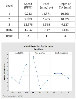
Fig 5: -Main effects plot for Tool wear
5.2 Taguchi Analysis for machining using
cryogenically treated tungsten carbide tool inserts
and vegetable oil.
A.
Cutting temperature
Table No. 11: - SN ratio for Cutting temperature
Exp.
No (RPM) Speed Feed (mm /rev)
Depth of cut (mm)
Cutting Tempera ture (oC)
SN Ratio
1 1200 0.10 0.5 28.3 -29.035
2 1200 0.12 1.0 28.2 -29.0050
3 1200 0.15 1.5 28.73 -29.1667 4 1400 0.10 1.0 28.81 -29.1909 5 1400 0.12 1.5 28.93 -29.2180 6 1400 0.15 0.5 28.97 -29.2390 7 1600 0.10 1.5 28.23 -29.3175
8 1600 0.12 0.5 28.6 -29.1273
[image:6.595.31.283.401.726.2]9 1600 0.15 1.0 28.5 -29.0969
Table No. 12: - Response Table for Cutting temperature
Fig 6: -Main effects plot for Cutting Temperature Level (RPM) Speed (mm/rev) Feed Cut (mm) Depth of
1 9.213 14.571 10.261
2 7.823 6.455 10.227
3 12.578 8.588 9.127
Delta 4.756 8.117 1.134
Rank 2 1 3
Level (RPM) Speed (mm/rev) Feed Cut (mm Depth of
1 -7.111 -5.196 -7.836
2 -6.586 -7.197 -4.612
3 -3.258 -4.561 -4.506
Delta 3.853 2.635 3.330
[image:6.595.318.561.469.748.2]© 2017, IRJET | Impact Factor value: 5.181 | ISO 9001:2008 Certified Journal
| Page 1764
[image:7.595.311.558.145.371.2]B.
Surface roughness
Table No. 13: - SN ratio for Surface roughness
Exp.
No (RPM) Speed
Feed (mm/r
ev)
Depth of cut (mm)
Surface Roughness
(µm)
SN Ratio
1 1200 0.10 0.5 2.340 -7.3843
2 1200 0.12 1.0 2.727 -8.7137
3 1200 0.15 1.5 1.827 -5.2347
4 1400 0.10 1.0 1.873 -5.5407
5 1400 0.12 1.5 1.890 -5.5392
6 1400 0.15 0.5 2.747 -8.7717
7 1600 0.10 1.5 1.373 -2.7534
8 1600 0.12 0.5 2.330 -7.3471
[image:7.595.22.268.147.376.2]9 1600 0.15 1.0 0.963 0.3274
Table No. 14: - Response Table for Surface roughness
Fig 7: -Main effects plot for Surface roughness
C.
Tool wear
Table No. 15:- SN ratio for Tool wear
Exp.
No (RPM) Speed
Feed (mm/ rev)
Depth of cut (mm)
Tool
wear SN Ratio
1 1200 0.10 0.5 0.130 17.7211
2 1200 0.12 1.0 0.685 3.2862
3 1200 0.15 1.5 0.145 16.7726
4 1400 0.10 1.0 0.085 21.4116
5 1400 0.12 1.5 0.645 3.8088
6 1400 0.15 0.5 0.620 4.1522
7 1600 0.10 1.5 0.140 17.0774
8 1600 0.12 0.5 0.125 18.0618
[image:7.595.38.551.396.722.2]9 1600 0.15 1.0 0.460 6.7448
Table No. 16: - Response Table for Tool wear
Fig 8:-Main effects plot for Tool wear Level (RPM) Speed (mm/rev) Feed Depth of Cut (mm
1 -29.07 -29.18 -29.13
2 -29.22 -29.12 -29.10
3 -29.18 -29.17 -29.23
Delta 0.15 0.06 0.14
Rank 1 3 2
Level (RPM) Speed (mm/rev) Feed Cut (mm Depth of
1 12.593 18.737 13.312
2 9.791 8.386 10.481
3 13.961 9.223 12.553
Delta 4.170 10.351 2.831
[image:7.595.302.559.400.719.2] [image:7.595.33.278.405.722.2]© 2017, IRJET | Impact Factor value: 5.181 | ISO 9001:2008 Certified Journal
| Page 1765
3. CONCLUSIONS
In conventional machining, the turning operation results in high heat generation which causes thermal cracks on the cutting tool and the workpiece surface there by reducing the life of the tool. In order to increase the tool life the cutting tool is cryogenically hardened.
Speed, feed, and depth of cut are the three cutting parameters selected for machining and were tested for three different levels of operation. Minitab 17 software was used to design the experiments by using Taguchi Factorial Design.
Experiments were conducted using two different tools i.e. untreated tungsten carbide tools (conventional machining) and cryogenically treated tungsten carbide tools on EN8 steel material.
Taguchi analysis was used to find optimum machining parameters and their results were compared to from Taguchi analysis using the signal to noise ratio and best results were obtained.
It is observed from this study that it shows drop in temperature when CT tools were used for machining which ranged from 28.2oC to 28.97oC.
.
Whereas with the use of UTit ranged from 29.100oC to 29.83oC.
Optimal machining condition for Cutting temperature: Speed= 1200 rpm.
Feed= 0.12 mm/rev. Depth of cut= 1 mm.
Results were compared and it was found that machining with CT tools gave better surface roughness.
Optimal machining condition for Surface roughness: Speed= 1600 rpm.
Feed= 0.15 mm/rev. Depth of cut= 1 mm.
Surface roughness= 0.963 µm.
It was also observed that the tool wear was significantly improved after the use of cryogenically treated tungsten carbide tools.
Optimal machining condition for Tool Wear: Speed= 1400 rpm.
Feed= 0.10 mm/rev. Depth of cut= 1 mm. Tool Wear= 0.085 mm.
REFERENCES
[1] Lakhwinder Pal Singh, Jagtar Singh Effects of “Cryogenic Treatment on High-speed Steel Tools’ Department of Mechanical Engineering, SLIET, Longowal, Sangrur, Punjab, India.
[2] D. Mohan Lal, S. Renganarayanan, and A. Kalanidhi, "Cryogenic treatment to augment wear resistance of tool and die steels", Cryogenics, Vol. 41, pp. 149-155, 2001.
[3] A.Y.L.Yong, K.H.W Seah, M. Rehman, (2006) “Performance of cryogenically treated tungsten carbide tools in milling operations.
[4] S. Khandekar, M. Ravi Sankar, V. Agnihotri, and J. Ramkumar, 2011 “nano cutting fluid for Enhancement of metal cutting performance. Materials and manufacturing processes,2011.
[5] Shrikant Borade and Dr.M.S.Kadam(2016) “comparison of main effect of vegetable
oil and al2o3 nanofluids
used with mql on surface roughness and
temperature”.
BIOGRAPHIES
Abhijit Rambhau Bhagat, a student of B.E (Mechanical Engineering) and working on the project of “Experimental Investigation and Optimization of Machining Parameters for Cryogenically Treated Tool and Nano-coolant” under the guidance of prof. S.B. Khandekar.
`
© 2017, IRJET | Impact Factor value: 5.181 | ISO 9001:2008 Certified Journal
| Page 1766
Abhay Shivdas Naik, a student of B.E(Mechanical Engineering) and working on the project of “Experimental Investigation and Optimization of Machining Parameters for Cryogenically Treated Tool and Nano coolant” under the guidance of prof.
Phati Prabhakar Sawant, a student of B.E (Mechanical Engineering) and working on the project of "Experimental Investigation and Optimization of Machining Parameters for Cryogenically Treated Tool and Nano coolant” under the guidance of prof. S. B. Khandekar.