© 2018, IRJET | Impact Factor value: 6.171 | ISO 9001:2008 Certified Journal | Page 1260
OPTIMIZATION OF LASER PROCESSING PARAMETERS
Kumavat Mukesh Manilal
1, Thorat S.C.
2,Deshmukh A.P.
3, Matsagar P.B.
4, Pagar A.B.
5, Raut R.R.
61,2 Assistant Professor, Mechanical Engineering Department, SND COE & RC Yeola, Savitribai Phule
Pune University (Pune), Maharashtra, India
3,4,5,6 UG Student (Mechanical Design), SND COE & RC Yeola, Savitribai Phule Pune University, Maharashtra, India
---***---Abstract –
In this study we are working on laser processingparameters and its optimization. To improve time required for process, improve surface hardness with minimum input of power as well as reinforced material quantity.
This work is completely for metal surface hardness by laser with constant power input. We also work on surface roughness and its effect.
Key Words: Laser, Surface Roughness, Gas, Sheet Thickness, Focal Point.
1. INTRODUCTION
Sheet metal of stainless steel and mild steel are the project material on which we perform the practical in order to study the effect of variation of the parameters.
Following is the study:
1. Keeping thickness of sheet metal constant.
2. Then laser power constant.
3. Effect of different gas used in laser cutting and there function.
4. Effect of focal point on cutting parameters.
5. Effect on surface roughness.
1.1. Laser
Laser (Light Amplification by Stimulated Emission of Radiation) is a coherent and amplified beam of electro-magnetic radiation.
1.2. Laser Cutting Process
Laser cutting is a common manufacturing process employed to cut many types of materials. Materials which may be cut included ferrous metal, non ferrous metal, stone, plastic, rubber and ceramic. Laser cutting works by directing a high power pulsed laser at a specific location on the material to be cut. The energy beam is absorbed into the surface of the material and the energy of the laser is converted into the heat, which melt or vaporize the material. Additionally gas is focused or blown into the cutting region to expel or blow away the molten melt and vapor from cutting path.
There are several advantage of laser cutting over mechanical cutting, since the cut is performed by the laser beam, there is no physical contact with the material therefore contaminates cannot enter or embed into the material.
Laser cutting can produce high quality cut, complex cut, cut several part simultaneously, produce clean cutting edge which require minimal finishing as well as low edge load during cutting which will reduce distortion
Laser cutting is a fairly new technology that allows metals to be cut with extreme precision. The laser beam is typically 0.2 mm in diameter with a power of 1-10 kW,
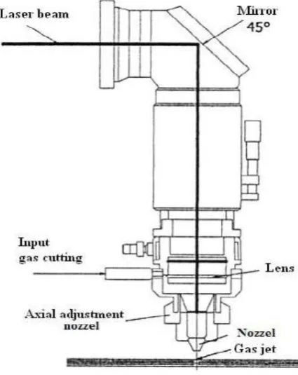
[image:1.595.315.528.438.706.2]Depending on the application of the laser cutter a selection of different gases are used in conjunction with the cutting. When cutting with oxygen, material is burned and vaporized when heated by the laser beam to ignition temperature.
© 2018, IRJET | Impact Factor value: 6.171 | ISO 9001:2008 Certified Journal | Page 1261 Figure no. 1.2 Experimental Setup of 3D Laser Cutting
Machine
Laser is a powerful source of light having extraordinary properties which are not found in the normal light sources like tungsten lamps, mercury lamps, etc. The unique property of laser is that its light waves travel very long distances with e very little divergence.
In case of a conventional source of light, the light is emitted in a jumble of e separate waves that cancel each other at random and hence can travel very short distances only. An analogy can be made with a situation where a large number of pebbles are thrown it into a pool at the same time. Each pebble generates a wave of its own.
Since the pebbles are thrown at random, the waves generated by all the pebbles cancel each other and as a result they travel a very short distance only. On the other hand, if the pebbles are thrown into a pool one by one at the same place and also at constant intervals of time, the waves thus generated strengthen each other and travel long distances.
In this case, the waves are said to travel coherently. In laser, the light waves are exactly in step with each other and thus have a fixed phase relationship.
1.3 Problem Statements
Minimize Surface roughness of sheet affected by process parameters. Optimization is done by using “Taguchi method”, with the aid of Minitab software.
1.4 Objective
There are 2 main objectives in this study:
(a) To determine the optimize parameters in cutting process.
1.5 Scope of Study
The scope of study is divided in three sections:
(a) Process parameters, (b) Sheet metal cutting and, (c) Taguchi method.
1.6 Taguchi Designs
Genichi Taguchi, a Japanese engineer, proposed several approaches to experimental designs that are sometimes called "Taguchi Methods." Taguchi proposed several approaches to experimental designs called Taguchi method.
This method utilizes an orthogonal array, which is a form of fractional factorial design containing a representative set of all possible combination of experimental conditions. Using Taguchi method, a balanced comparison of levels of the process parameters and significant reduction in the total number of required simulations can both be achieved.
Application of T.M. is aimed at the following objectives:
1. To establish the best or the optimum condition for a products or a process.
2. To estimate the contribution of individual parameters.
3. To estimate the response under the optimum conditions.
2. EXPERIMENTAL WORK
2.1 Relation between Cutting Speed and Laser Power
a) Cutting speed: - sheet metal cut speed by a laser in mm/min.
b) Laser power: - power assisted by laser to penetrate and cut the sheet in watt.
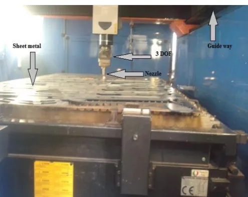
[image:2.595.38.286.76.272.2]2.1.1 Experiment No. 1
Table No.1 General Data of Process Parameter
Material thickness
(mm) 2 4 6 8
Gas pressure
(bar) 10 10 7 7
Laser power
(watt) 700 800 800 900
Cutting speed
(mm/min) 3000 1800 1000 800
© 2018, IRJET | Impact Factor value: 6.171 | ISO 9001:2008 Certified Journal | Page 1262 2.1.2 Experiment No. 2
At constant thickness, to check other process parameter such as Laser Power and cutting Speed.
a) Material – Mild Steel b) Assist gas pressure – 10 Kpa
2.1.2.1 For 2mm Thickness of Sheet
Table no. 2
Laser Power(watt) Cutting Speed(mm/min)
400 800
500 1000
600 1500
700 2500
800 3000
2.1.2.2. For 3mm Thickness of Sheet
Table no. 3
Laser Power(watt) Cutting Speed(mm/min)
400 600
500 800
600 1000
700 2000
800 2500
2.1.2.3. For 4 mm Thickness of Sheet
Table no. 4
Laser Power(watt) Cutting Speed(mm/min)
500 300
600 500
700 800-900
800 1000-1200
900 1500(MAX.)
Thus from above we come to know that, if we increased Laser Power then increase cutting speed at constant thickness
2.1.2 2.1.3 Experiment No. 3
a) For Stainless Steel Material
For constant laser power variation of cutting speed with respect to thickness of sheet
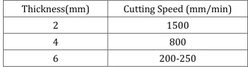
2.1.3.1 For 400 watt power
Table no. 5
Thickness(mm) Cutting Speed (mm/min)
2 1500
4 800
6 200-250
2.1.3.2. For 500 watt power
Table no. 6
Thickness(mm) Cutting Speed (mm/min)
2 2000
4 1200
6 800
2.1.3.3. For 700 Watt Power
Table no. 7
Thickness(mm) Cutting Speed (mm/min)
2 3000
4 1400
6 1000
b) For mild steel material :
2.1.3.4. For 400 Watt Laser Power
Table no. 8
Thickness(mm) Cutting Speed (mm/min)
2 800
4 300
6 50-90
2.1.3.5. For 500 watt power
Table no. 9
Thickness(mm) Cutting Speed (mm/min)
2 1000
4 300
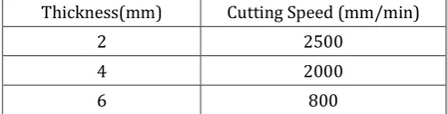
[image:3.595.311.554.128.194.2]© 2018, IRJET | Impact Factor value: 6.171 | ISO 9001:2008 Certified Journal | Page 1263 2.1.3.6. For 700 watt power
Table no. 10
Thickness(mm) Cutting Speed (mm/min)
2 2500
4 2000
6 800
From above experiment we come to know that cutting speed decreases with increase in material thickness at constant power supply
3. METHODOLOGY
3.1.1 Experimental Plan and Details:
In this study, three machining parameters were selected as control factors, and each parameter was designed to have three levels, denoted 1, 2, and 3 (Table 1). The experimental design was according to an L’9 array based on Taguchi method, while using the Taguchi orthogonal array would markedly reduce the number of experiments.
A set of experiments designed using the Taguchi method was conducted to investigate the relation between the process parameters and response factor. Minitab 17 software is used to optimization and graphical analysis of obtained data.
[image:4.595.38.284.130.193.2]3.1.2 Process parameter and levels
Table no. 11 Process parameter and levels
Symbol parameter Process Level 1 Level 2 Level 3
P Power(kw) Laser 1600 1800 2000
V Cutting Speed (mm/min) 900 1200 1500
G Gas pressure (mm) 14 15 16
The quality of design can be improved by improving the quality and productivity. Robust design is an engineering methodology for obtaining product and process condition, which are minimally sensitive to the various causes of variation, and which produce high-quality products with low development and manufacturing costs.
Taguchi’s parameter design offers a simple, systematic approach and can reduce number experiment to optimize design for performance, quality and cost. Surface roughness has received serious attention for many years.
It has formulated an important design feature in many situations such as parts subject to fatigue loads, precision fits, fastener holes, and aesthetic requirements. In addition to tolerances, surface roughness imposes one of the most critical constraints for the selection of machines and cutting parameters.
A considerable number of studies have investigated the general effects of the speed, feed, and depth of cut on the surface roughness. Process modeling and optimization are the two important issues in manufacturing products.
A greater attention is given to accuracy and surface roughness of product by the industry these days. Surface finish has been one of the most important considerations in determining the machining ability of materials. Surface roughness and dimensional accuracy are the important factors required to predict machining performances of any machining operations.
Optimization of machining parameters not only increases the utility for machining economics, but also increases the product quality to a great extent. In this context, an effort has been made to estimate the surface roughness using experimental data. Since turning is the primary operation in most of the production processes in the industry, surface finish of turned components has greater influence on the quality of the product.
Surface finish in turning has been found to be influenced in varying amounts by a number of factors such as feed rate, work material characteristics, work hardness, unstable built-up edge, cutting speed, depth of cut, cutting time, tool nose radius and tool cutting edge angles.
4.1. Taguchi Orthogonal Array:
If there is an experiment having 3 factors which have four values, then total number of experiment is 81. Then results of all experiment will give 100 accurate results. In comparison to above method the Taguchi orthogonal array make list of nine experiments in a particular order which cover all factors.
4.2. Experimentation: -
The whole experimentation is divided into different steps. All the steps are discussed in detail below:
4.2.1 Maximum Limits of Operating Parameters
There are three machining parameters i.e. laser power, cutting speed, gas pressure. Different experiments are done by varying one parameter and keeping other two fixed so maximum value of each parameter was obtained. Operating range is found by experimenting with top laser power and taking the lower levels of other parameters. A combination of all three parameters is found beyond which tool or job fails.
© 2018, IRJET | Impact Factor value: 6.171 | ISO 9001:2008 Certified Journal | Page 1264 4.2.2Experiment Performed:-
Experiments are performed according to the selected design of experimental parameter as shown in Table. Machining time is noted by stopwatch and measured final surface finish of all jobs.
4.2.3. Observation
In the run nine experiments are performed and surface finish is calculated. This is given in below table no.12.
Table No.12
Sr. No Laser Power
(Kw)
Cutting speed (mm/min)
Gas pressure (bar)
1 1600 1000 0.5
2 1600 800 0.6
3 1600 600 0.7
4 1800 1000 0.5
5 1800 800 0.6
6 1800 600 0.7
7 2000 1000 0.5
8 2000 800 0.6
9 2000 600 0.7
5. STUDY ON EFFECT OF GAS USED IN LASER BEAM
MACHINE AND SELECTION OF FOCAL POINT
5.1 Gas Study
a) N2 gives better surface finish than O2 [2].
b) N2 is used to cut stainless steel sheet because N2 give white cut due to its purity[2].
c) O2 is used to cut mild steel sheet [2].
d) (CO2(12%)+He(64%)+ N2(24%)) used to create laser for cutting purpose [2].
e) (O2 , N2) used to create pressure. N2 used to create laser is pure N2[2].
5.2 Focal Point
a) The depth of penetration is proportional to amount of power but also depend on location of focal point [4]. b) For M.S. sheet focal is positive i.e. above the sheet metal,
while for S.S sheet focal is negative i.e. below or middle of the metal sheet[4, 5].
6. SUMMARY
In this project, performing the experiment on Laser Beam Machine, we are able to find the optimum machining parameter which affects the surface finish of the work piece. And also the effects of machining parameters on S-N ratio i.e. signal to noise ratio. In this study, the Grey relational based Taguchi method
was applied for the multiple performance characteristics of cutting operations. A grey relational analysis of the surface roughness obtained from the Taguchi method reduced from the multiple performance characteristics to a single performance characteristic which is called the grey relational grade.
Therefore, the optimization of the complicated multiple performance characteristics of the processes can be greatly simplified using the Grey relational based Taguchi method. With this work we came to know studied that the cutting parameters like focal point, cutting speed and laser power greatly affects on laser cutting operation, which indirectly affects the surface roughness values.
It is also shown that the performance characteristics of the cutting operations, such as the surface roughness may be enhanced by using this method.
ACKNOWLEDGEMENT
We take the opportunity to express our deep sense of gratitude and whole hearted thanks to our respected guides Prof. Kumavat M. M., for invaluable guidance, inspiration and encouragement throughout the work. We are greatly in debated to them in piloting us whenever we face difficulties in our work.
REFERENCES
[1] International Journal of Engineering Research and Applications Vol. 2, Issue 2,Mar-Apr 2012, pp.1190-1196,“Optimization of High Power CO2 Laser Machining Centre’s Machining Parameters by Experimental Analysis”, Prof. Dhaval P. Patel, Mrugesh B. Khatri / , www.ijera.com
[2] International Journal For Technological Research In Engineering, vol.1 issue:2, March-2015“LITERATURE SURVEY ON LASER CUTTING MACHINE PROCESS PARAMETER” NAIMESH R. KADIYA, Department of Mechanical Engineering, Indus Institute of Technology and Engineering, Rancharda, Ahmedabad, Gujarat, India
[3] Nonconventional Technologies Review., “APPLICATION OF THE TAGUCHI METHOD FOR OPTIMIZATION OF LASER CUTTING: A REVIEW” Romania, December, [email protected]
© 2018, IRJET | Impact Factor value: 6.171 | ISO 9001:2008 Certified Journal | Page 1265 [5] International Journal For Technological Research In
Engineering Volume 1, Issue 5, January – 2017 ISSN (Online) : 2347 – 4718 “OPTIMIZATION OF INPUT PARAMETERS ON SURFACE ROUGHNESS DURING LASER CUTTING - A REVIEW” Vipul K Shah, Mr. Hardik J Patel ,Sardar Patel Institute of Technology U V Patel College of Engineering Gujarat, India.
[6] International Journal Of Computational Engineering Research (ijceronline.com) Vol. 2 Issue. 5 “CONTROL PARAMETERS OPTIMIZATION OF LASER BEAM MACHINING”, Ruben Phipon1, B.B.Pradhan, Mechanical Engineering Department, SMIT, Sikkim, India
BIOGRAPHIES
Prof. Kumavat Mukesh Manilal. [email protected] BE Mechanical
SRES COE Kopaagaon (PUNE) ME Design
SND COE & RC Yeola (PUNE)
Abhinay Prabhakar Deshamukh. SND COE & RC YEOLA,
BE-Mechanical.
Amol Babasaheb Pagar. SND COE & RC YEOLA, BE-Mechanical.
Prashant Bhausaheb Matsager. SND COE & RC YEOLA,
BE-Mechanical.
Rajendra Rambhau Raut. SND COE & RC YEOLA, BE-Mechanical.
Author Photo
Author Photo
3rd Author
Photo 1’st Author