Built environment reverse and forward
prototyping
Arayici, Y, Hamilton, A and Gamito, P
Title Built environment reverse and forward prototyping Authors Arayici, Y, Hamilton, A and Gamito, P
Type Conference or Workshop Item
URL This version is available at: http://usir.salford.ac.uk/12472/ Published Date 2005
USIR is a digital collection of the research output of the University of Salford. Where copyright permits, full text material held in the repository is made freely available online and can be read, downloaded and copied for noncommercial private study or research purposes. Please check the manuscript for any further copyright restrictions.
BUILT ENVIRONMENT REVERSE AND FORWARD
PROTOTYPING
Yusuf Arayici, Andy Hamilton
School of Construction and Property Management, University of Salford, Greater Manchester, M6 6AP
Pedro Gamito
Universidade Lusofona de Humanidades e Technologies Av. Do Campo Grande, 376
1749-024 Lisbon, Portugal
Advanced digital mapping tools and technologies are enablers for effective e-planning in the built and human environment. The regeneration and transformation of cities from the industrial age to the knowledge age is essentially a ‘whole life cycle’ process consisting of; planning, development, operation, reuse and renewal. The use of the 3D laser scanner enables digital documentation of buildings, sites and physical objects for reconstruction and restoration. Using the 3D scanner in combination with the 3D printer provides the transformation of digital data from the captured CAD model back to a physical model at an appropriate scale – reverse prototyping. Furthermore, it can possible to make the building information ready in a database for building lifecycle by means data conversion with pattern matching approach from the laser scanned data. The use of these technologies is a key enabler to the creation of new approaches to the ‘Whole Life Cycle’ process within the built and human environment for the 21st century.
Keywords: CAD, Intelcities, Laser scanner, Pattern matching, Modelling
1. INTRODUCTION
Recently, new instruments have been introduced in the field of surveying that are able to acquire portions of land and objects of various shapes and sizes in a quick and cheap way. These instruments, based on laser technology, are commonly known as terrestrial laser scanners. While laser scanner instruments based on the triangulation principle and high degrees of precision have been widely used since 80’s, TOF (Time of Flight) instruments have been developed for metric survey applications only in the last 5 years (Bornaz & Rinaudo, 2004).
These types of laser scanners can be considered as highly automated total stations. They are usually made up of a laser, which has been optimised for high speed surveying, and a set of mechanisms that allows the laser beam to be directed in space in a range that varies according to the instrument that is being used. For each acquired points, a distance is measured on a known direction: X, Y, and Z coordinates of a point can be computed for each recorded distance direction. Laser scanners allow millions of points to be recorded in a few minutes. Because of their practicality and versatility, these kinds of instruments are today widely used in the field of architectural, archaeological and environmental surveying (Valanis & Tsakiri, 2004).
density point data without the need for a reflector system. Merged data clouds have sufficient points to negate the need for EDM interpolation techniques potentially providing the optimum representation of any scanned surface. 3D laser mapping enables the recording of slight differences that exist in the physical world and has been used for a variety of sectors which range from industrial applications for process automation in automotive industry to robotics. Current research applies these techniques to building and urban scale digital data capture. Technologies such as 3D printing allow for the creation of the fine detail models from the digital record to the physical environment.
The paper explains the Intelcities project and the research undertaken in the project about the laser scanner technology.
2. THE INTELCITIES PROJECT
The INTELCITIES (Intelligent Cities) Project is a research and development project that aims at helping achieve the EU policy goal of the knowledge society. INTECLITIES project brings together the combined experience and expertise of key players from across Europe, focusing on e-Government, e-Planning and e-Inclusion, e-Land Use Information Management, e-Regeneration, Integration and Interoperability, Virtual Urban Planning,
et
The overall aim is to advance the possibilities of eGovernance of cities to a new level through the development of a prototype of the IOSCP (Integrated Open System City Platform), as a clear and easily accessible illustration of a shared civic place in virtual space continuously available to all – whether officials, decision-makers and other professionals, such as planners, developers, politicians, designers, engineers, transport and utility service providers, as well as individual citizens, community groups/networks and businesses, through a wide range of interfaces
This paper focuses on the e-Regeneration work package in which there are two main tasks identified for the use of laser scanner technology (Arayici, et al, 2004). These are as follows:
The building data capture: Capture of digital data of existing buildings using 3D laser scanning equipment. Show how this data can be used as an information base to enhance the refurbishment process.
Building data integration: Build concept nD modelling system and relate to other data structures including relational databases to illustrate how data can be integrated to support intelligent city systems.
The rest of the paper elaborates the research on building data capture and integration in the Intelcities project.
3. THE CONCEPTUAL SYSTEM OF BUILDING DATA INTEGRATION
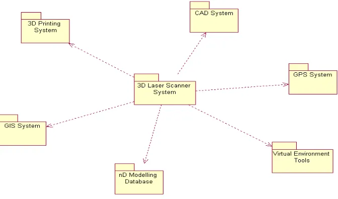
the 3D printing system for hard modelling and with the nD modelling repository for storing the information produced with the laser scanning system in a database that embraces information in various formats for future use during the refurbishment process.
Figure 1: The packages of the building data integration system
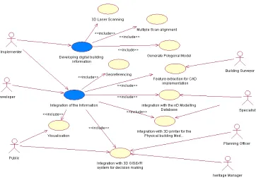
The use case diagram developed in intelcities project illustrates the building data integration system. In this activity, the use cases were used for the conceptual modelling of what the system should do from the user’s point of view. Thus, use cases act as the common language for communication between the stakeholders. The use case diagram below (Figure 2) further elaborates the interaction and integration of the laser scanning systems with the other systems.
Figure 2: Use case diagram for the conceptual modelling of the 3D Laser scanning system
The following section describes the integration of the laser scanner technology with 3D printer and Virtual Environment tools.
3.1. Real World Building Data Modelling
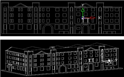
Figure 3: Polygonal VR mesh models developed from the raw scan data and CAD models extracted from the VR models, Jactin house Intelcities project
This innovation is significant because it has potential to solve the problems that are always been associated with design and construction of existing buildings for reuse goals. For example, it can provide faster, better quality and more precise analysis and feature detection for building survey (Arayici, et al, 2004).
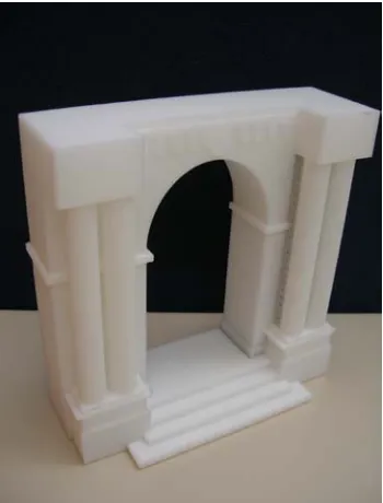
The system can collect data from different sources and manipulate it for their integration. For example; the geometry information can be obtained by using 3D scanner. By editing and integrating those data, an nD model of the object (building/urban area) could be created to be used for decision-making process. The model can be presented in different ways, for example, physical model or VR projection system for reverse and forward prototyping. An example for physical modeling and VR projection system are illustrated in Figure 4, 5 and 6.
For instance, in regard to cultural heritage, many historical sites are slowly deteriorating due to exposure to the elements. Although remediation efforts can reduce the rate of destruction, a digital model of the site will preserve it indefinitely. Models of historical artefacts also allow scientists to study the objects in new ways. For example, archaeologists can measure artefacts in non contact fashion, which is useful for fragile objects. Also digital models allow objects to be studied remotely, saving time and travel expenses and enabling more archaeologists to study them.
reverse engineer manufactured parts for which a CAD model is unavailable or never existed. Modelling from reality imports the prototype into a computer, creating a digital model that can be edited with a CAD program.
Regarding architecture and construction, architects frequently need to determine the “as built” plans of building or other structures such as industrial plants, bridges, and tunnels. A 3D model of a site can be used to verify that it was constructed according to specifications. When preparing for a renovation or a plant upgrade, the original architectural plans might be inaccurate, if they exist at all. A 3D model allows architect to plan a renovation and to test out variousconstruction options.
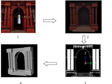
Figure 4: the process of creating physical models from digital laser scanned data
[image:7.612.137.525.209.499.2]In the above figure, the first picture labeled 1 is the point cloud raw data captured by the laser scanner. The second image is the polygonal mesh VR model produced from the raw scan data in the Polyworks modeler, the third image is the CAD model extracted from the VR model in the second image. The fourth image is the solid model in STL format (Standard Template Library) for 3D printing to produce the physical model. Figure 5 shows the picture of physical model produced.
1 2
Figure 5: Printed physical model of the peel building in figure 4
Figure 6: Peel building model is presented in VR Projection System
3.2. 3D Scanned data to nD modelled data (Ongoing research)
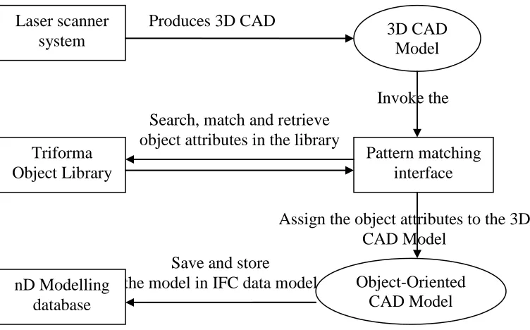
Figure 7: Object recognition approach for laser scanned building data
According to figure 7, 3D CAD models using semi-automated and fully automated techniques are extracted from the polygonal mesh model developed in the laser scanner system. The extracted CAD model is presentable in any commercial CAD software. The pattern matching interface being designed will invoke the 3D CAD model to its display screen. Highlighting any building frame in the model will enable the pattern matcher to define geometric features as criteria for matching process such as shape, sides, width, height, thickness, line type, line thickness, line colour and so on. Beside the automatic feature recognition, users can also input further criteria for matching process.
Microstation triforma employs a single building model concept. All information about a building is recorded in a 3 dimensional model. Traditionally a given door in a building would be drawn in at least three or four places (plan, building elevation, building section, interior elevation, etc). In the single building model, it is constructed once and these various drawings are later extracted automatically. The single building model requires building objects, which are defined, edited and stored in the triforma library.
The Pattern matcher will access the triforma library with the criteria in hand to do search and match. Two different type of matching can be done such as exact pattern matching and approximate pattern matching. Exact pattern matching consists of finding the exact pattern looked for. In the case of approximate pattern matching, it is generalisation of the pattern looked for and a determined number of differences between the pattern looked for and the objects found in the library is allowed.
It is considered that there will be three types of pattern form: These are simple, constrained, and variable. All three forms can be accommodated by the pattern matcher interface. However, it will handle them differently to improve efficiency.
Assign the object attributes to the 3D CAD Model
Save and store
the model in IFC data model Search, match and retrieve object attributes in the library
Invoke the Produces 3D CAD
Laser scanner
system 3D CAD Model
Simple patterns are simple matches on values (Frederiksson, Navarro, 2004). The pattern describes which values must be included in the search. For example, the pattern matcher tries to match an instance of a square (a frame) and it finds square-1, square-2, square-3 and square 4, all the squares in the example database.
In terms of constrained pattern form, it is possible to specify a constraint on a value instead of a specific value (Ferragina, 2004). To do so, a function to be provided will test the constraint. For example, the pattern matcher matches the frame to the triangle -1, triangle -2, triangle -3 and triangle 4. The constraint (value <4) limits the value of sides to be less than 4.
In respect to variable type of pattern form, patterns may also include variable references (Csuros, 2004). Variables in patterns can be used to relate values. The first occurrence of a variable in a pattern causes the value in a frame to be bound to that variable. The second occurrence forces a constraint that the value will be equal to the value bound to the variable. For example, pattern (width a, height a) describes objects with width equal to height.
Variables may also be used in constraints to relate values by more complex relations than simple equality. For example, the pattern (width a, height {value>a) describes objects with height greater than width. Variables may also be used to relate values across patterns. Since each pattern refers to values in a single frame, relating values across frames requires multiple patterns (Yates, 2004). The function multiple-pattern match searches for frames that match a set of related patterns. Multiple-pattern –match returns a list of lists in which the sub lists contain the value of variables followed by the frames that matched each pattern within the set. The variables also can be related across frames with constraints. For example, pattern (width a, height {value >a}, sides 4) describes all objects with height greater than width and the sides with four.
As a result of various matching processes, object recognition can be worked out for the interested building frames in the 3D CAD model. Attributes of the objects matched in the library will be assigned to the building frame in the CAD model, which result in the building frames to be building objects defined. Subsequently, object-oriented (OO) CAD model will be obtained. This OO CAD model will be mapped into IFC schema to save and store the model in IFC data model into the nD modelling database.
4. CONCLUSION
The paper explained the research on the use of laser scanner technology for built environment. The focus was the e-regeneration to facilitate the building refurbishment process. Therefore, building data capture by laser scanner and building data integration with various systems are addressed.
5. REFERENCES
Arayici, Y., Hamilton, A., Gamito, P., Albergaria, G., 2004, The Scope in the INTELCITIES Project for the Use of the 3D Laser Scanner, in the Proceeding of ECT2004: The Fourth International Conference on Engineering Computational Technology, 7-9 September 2004, Lisbon, Portugal. ISBN 0948749962 pp 111-112.
Bornaz L., Rinaudo F., 2004, Terrestrial Laser Scanning Data Processing, 20th ISPRS Congress, 12-23 July 2004, Istanbul Turkey, pp514-520.
Csuros, M., 2004, Performing local similarity searches with variable length seeds, in the proceeding of Combinatorial Pattern Matching Conference (CPM), July 2004, Istanbul. Ferragina, P., 2004, On Compression and Indexing: two sites of the same coin, in the proceeding of Combinatorial Pattern Matching Conference (CPM), July 2004, Istanbul. Frederiksson, K., Navarro, G., 2004, Improved Single and Approxmiate String Matching, in the proceeding of Combinatorial Pattern Matching Conference (CPM), July 2004, Istanbul.
Johnson, M., 2002, A simple pattern matching algorithm for recovering empty notes and their antecedents, Proceeding of 40th Annual Meeting of the Association for computational Linguistics (ACL), Philadelphia, July 2002, pp136-143.
Valanis A., Tsakiri M., 2004, Automatic Target Identification for Laser Scanners, 20th ISPRS Congress, 12-23 July 2004, Istanbul Turkey, pp1-6.