A hapticenabled multimodal interface for
the planning of hip arthroplasty
Tsagarakis, NG, Gray, JO, Caldwell, DG, Zannoni, C, Petrone, M, Testi, D and
Viceconti, M
http://dx.doi.org/10.1109/MMUL.2006.55
Title
A hapticenabled multimodal interface for the planning of hip arthroplasty
Authors
Tsagarakis, NG, Gray, JO, Caldwell, DG, Zannoni, C, Petrone, M, Testi, D
and Viceconti, M
Type
Article
URL
This version is available at: http://usir.salford.ac.uk/936/
Published Date
2006
USIR is a digital collection of the research output of the University of Salford. Where copyright
permits, full text material held in the repository is made freely available online and can be read,
downloaded and copied for noncommercial private study or research purposes. Please check the
manuscript for any further copyright restrictions.
For more information, including our policy and submission procedure, please
M
ultimodal environments seek to create computational scenarios that fuse sensory data (sight, sound, touch, and perhaps smell) to form an advanced, realistic, and intu-itive user interface. This can be particularly com-pelling in medical applications, where surgeons use a range of sensory motor cues.1-4Sampleapplications include simulators, education and training, surgical planning, and scientifically ana-lyzing and evaluating new procedures.
Developing such a multimodal environment is a complex task involving integrating numer-ous algorithms and technologies. Increasingly, researchers are developing open source libraries and toolkits applicable to this field such as the Visualization Tool Kit (VTK)for visualization, the Insight Toolkit (ITK)for segmentation and regis-tration, and the Numerical Library (VNL) for numerical algorithms. Single libraries from these toolkits form a good starting point for efficiently
developing a complex application. However, this usually requires extending the core implementa-tion with new library modules. In addiimplementa-tion, inte-grating new modules can quickly become confusing in the absence of a good software architecture.
To address this, researchers have developed semicomplete application frameworks that can run independently, hiding the core implementa-tion’s complexity. As such, they can be dedicat-ed to produce custom applications.5However,
these systems form frameworks that aren’t mul-timodal because they don’t let us integrate dif-ferent visual representations or other modalities such as haptics and speech. This has motivated research in developing truly multimodal frame-works,6but the benefits of such integration are
still largely unexplored. For the haptic modality in particular, hardware and software that can provide effective touch feedback can enhance the growth of innovative medical applications.
From this rationale, the Multisense project aims to combine different sensory devices (hap-tics, speech, visualization, and tracking) in a unique virtual reality environment for orthope-dic surgery. We developed the Multisense demonstrator on top of a multimodal application framework (MAF)7 that supports multimodal
visualization, interaction, and improved syn-chronization of multiple cues.
This article focuses on applying this multi-modal interaction environment to total hip replacement (THR) surgery and, in particular, to the preoperative planning surgical-access phase.8
After validation, this approach will be highly rele-vant to other orthopedic and medical applications.
Hip arthroplasty planner
Hip arthroplasty is a procedure in which dis-eased hip joints are removed and replaced with artificial parts—the socket and prosthesis. Researchers have developed different systems for THR preoperative planning,4,9operating in 2D
using a mouse and flat screen to produce pseudo-3D interaction. This approach makes little or no use of multisensory inputs, which leads to prob-lems because the graphics interface strongly affects implant positioning accuracy.10
A team of orthopedic surgeons defined four specific tasks that form the basis for our multi-modal hip arthroplasty planning environment:
❚ Preparing the subject-specific musculoskeletal model.Effective planning requires a complete
A Haptic-Enabled
Multimodal
Interface for
the Planning of
Hip Arthroplasty
Nikolaos G. Tsagarakis, John O. Gray,
and Darwin G. Caldwell
University of Salford, UK
Cinzia Zannoni and Marco Petrone
Biocomputing Competence Center
(CINECA)
Debora Testi and Marco Viceconti
Institute of Orthopedics Rizzoli
Haptic User Interfaces for Multimedia Systems
Multimodal
and accurate musculoskeletal model usually only available from magnetic resonance imag-ing (MRI) data. Related work shows how we can map patient computerized tomography (CT) scans to data and models from the Visual Human to provide complete bone and soft tis-sue models of the hip and thigh muscles.10 ❚ Surgical-access planning.The critical
surgical-access phase consists of three main surgical tasks: determining the initial incision location and size, retracting the muscles, and dislocat-ing the femur.
❚ Components positioning.Here the surgeon posi-tions the prosthesis with respect to the femur. During this process, the surgeon can check functional indicators: feasibility of the planned position, primary component stabil-ity, and range of joint motion.
❚ Surgical simulation.After determining the pros-theses’ pose, the surgeon can interactively position the neck resection plane to verify the reamer’s insertion path. Once the surgeon accepts that position, the system generates a model of the postoperative anatomy for final verifications and inspections.
The medical users exploited these surgical activities to identify the possible benefits that can be gained on these tasks by integrating the haptic modality in the preoperative planning applica-tion. Based on this study, we defined the haptic requirements of this specific application.
Haptic requirements
From this series of procedures, the medical users selected scenarios in which they felt haptic feedback would be of the greatest benefit. These included the ability to locate and size the inci-sion, evaluate the surgical access they can achieve through that incision, and identify the functional impairment produced by any damage to the soft tissues (muscle or skin).
In addition, haptic feedback can help position and orient the implant while preventing the sur-geon from positioning the component in a non-feasible location. Based on the position and orientation selected, the surgeon can evaluate this specific location using a number of haptic-enabled indicators including the thigh joint’s range of motion after the simulation and the component’s stability. The benefits will include
accurately positioning the implant and improved execution time.
Considering these surgical activities, the med-ical users defined the following haptic tasks:
❚ Force feedback for evaluating surgical access.
Force (or touch) feedback can help surgeons accurately locate and size an incision. During the retraction, it can help surgeons estimate the relationship between visibility and mus-cle damage. Force feedback can also help them evaluate the incision aperture size while dis-locating the femur.
❚ Force feedback for evaluating the planned-posi-tion feasibility.Reaction forces generated by contact with the surrounding tissues let the user refine the planned position, check the feasibility of planned position, and evaluate the component’s primary stability in this position.
We identified the multimodal interface’s requirements using the characteristics of these haptic tasks. These requirements let us determine the necessary features of the multimodal system’s software and hardware modules.
Multimodal system requirements
Any multimodal system must interact with complex data incorporating several features:
❚ integration of multiple I/O devices and modalities;
❚ seamless synchronization of the different update loops running at much different rates;
❚ a distributed architecture that copes with the computational load and simulation loops;
❚ support for complex multimodal visualization with multiple representation of the data;
❚ support for dynamically exchangeable haptic rendering algorithms; and
❚ modularity and extensibility, with simple application-level modules hiding the system architecture’s complexity and synchroniza-tion problems.
We developed a multimodal application frame-work to address these requirements and a suitable
41
haptic software and hardware device to provide the haptic modltity within the framework.
Multimodal application framework
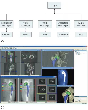
The multimodal application framework (MAF) is a software library for rapidly developing inno-vative multimodal environments for medical applications. It supports the Multimodal Display and Interaction (MDI) paradigm with multimodal visualization and interaction, haptics, and syn-chronization of the multiple cues. An MAF con-sists of components that control system resources, which are organized as data entities and applica-tion services. A data entity is a Virtual Medical Entity (VME). We distinguish the application ser-vices views, operations (Op), GUIs, and deser-vices.
Every MAF application is an instance of a logic component. The logic component’s main role is to control communication. Figure 1a shows the MAF architecture with the logic, manager, and all MAF resources. Figure 1b gives an example of the MAF multidisplay paradigm we used in this application.
Interaction and synchronization model
User interaction involves the I/O devices, views subsystem, and operation subsystem. The MDI paradigm requires gathering, synchronizing, and integrating inputs coming from multiple I/O devices. When users interact with the applica-tion, a stream of events is sent to the framework: discrete events (low-frequency events causing a change in the application state) and continuous events (high-frequency user interactions).
Handling input events is complex because the user might perform any set of interactive and dynamic actions. Thus, managing the interaction with a single, monolithic component is imprac-tical. MAF involves collaboration among many components. GUI events are processed directly by application components (for example, opera-tions or logic), and events coming from I/O devices are typically processed by specific objects namedinteractors. The general MAF interaction model for I/O devices implies three elements: a semiotic unit (I/O device), semantic unit (inter-actor), and an application component.
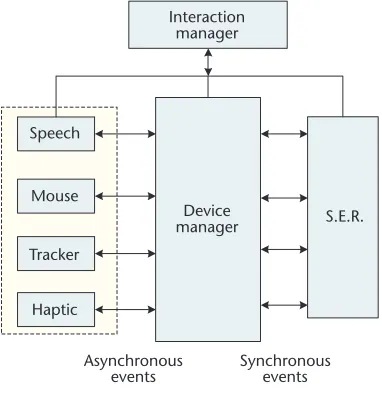
MAF manages interactions with multiple I/O devices, through routing, locking, and fusion mechanisms within the Interaction Manager. This synchronizes inputs from different devices using the Device Manager subcomponent responsible for keeping the list of connected devices and for synchronizing their inputs with the application’s main visualization loop (see Figure 2). For haptic devices, which require high and decoupled update rates, high-speed loops run inside the haptic subsystem, and only events sent at visualization rates pass to and from the MAF. MAF ensures synchronization by sending events to them—for example, each time a hap-tic surface rendering is started an event contain-ing the rendered surface is sent to the haptic device and, hence, to the haptic rendering serv-er/library. This data synchronization is rare, so it has minimal overhead.
During continuous interaction, the visualiza-tion and haptic loops are synchronized by the haptic device sending events (at the graphics rate) to the visualization loop. Hence, we can compute haptic and graphical models in a decoupled but synchronized fashion.
System hardware architecture
To address the intensive computation needs and particularly to accommodate the different update rates (for example, visualization systems update at 50 to 100 Hz while haptic devices
IEEE MultiMedia
Logic
Devices View VME Operation GUI
Interaction manager
View manager
VME manager
Operation manager
Main window
(a)
(b)
[image:4.585.40.332.63.430.2]update at more than 1,000 Hz), the multimodal system architecture uses multiple networked ded-icated machines (see Figure 3).
We use a dedicated graphics server to perform the graphics rendering, and the haptic server manages the haptic subsystem via a TCP/IP inter-face. The advantage of this approach over a sin-gle machine, multithreaded approach is that it minimizes the coupling between local rates run-ning on different machines. Also, the rates for critical processes such as the haptic servo input and feedback control process are more consis-tent, enabling stable haptic rendering even for complex environments. This approach also gives us separate, extensible, and reconfigurable con-trol of the different input feedback subsystems. The disadvantage is it increases synchronization requirements between the various subsystems, which the MAF directly addresses.
Haptic subsystem implementation
We designed a haptic device to support either one- or two-handed operation and fabricated it to suit the application workspace and interaction requirements we defined earlier. The device con-sists of two three-degrees-of-freedom (DOF) closed-chain mechanisms, each forming a classic five-bar planar device that can also be rotated around the axis along its base (see Figure 4a, next page). We selected the inner and outer link lengths to provide a workspace that satisfies the motion-range requirements of both the surgical-access and the component-position-feasibility tasks.
To support two-handed interactions, we can configure the device to work in two modes. The
double-independent mode provides two mecha-nisms (6-DOF input and 3-DOF feedback) with two separate haptic interface points; the coupled mode configuration provides a single linked
43
(a) (b)
Interaction manager
Speech
Asynchronous
events Synchronousevents Mouse
Tracker
Haptic
Device
manager S.E.R.
Logic
Interaction
manager managerView
Selected view
Camera interactor
Selected VME
Positional routing
Static event routing Behavior P.E.R.
VME
manager Operationmanager
Running operation
[image:5.585.61.252.69.266.2]Static interactor S.E.R.
Figure 2.
(a) Synchronizing the device’s events, and (b) multimodal application framework (MAF) static and positional event routing (S.E.R. and P.E.R.).
(a) (b)
Immersive visual display Orthopedic
surgeon
Virtual models
Multisense processing
unit
Tracking subsystem
Speech recognition
subsystem Haptic
[image:5.585.48.550.529.713.2]subsystem
Figure 3.
mechanism (6-DOF input and 5-DOF feedback).11
The haptic rendering library coordinates the input and haptic feedback signals. We developed this library to support the haptic modality within the MAF (see Figure 4b). We use a multithreaded approach that includes four core processes: device control, haptic rendering, event and command handling, and communication. Four respective managers manage these process threads.
We provide a haptic tool as a mechanism for force feedback and couple it to the haptic device within the haptic manager object. The haptic rendering process, managed by the haptic man-ager, uses the current tool to gather force requests within the haptic world space and asks the device to supply the user with the comput-ed haptic fecomput-edback. The haptic subsystem runs on a dedicated haptic machine, and
communi-cation between the haptic module and the visu-alization station is performed using the haptic subsystem API.
Surgical-access haptic modules
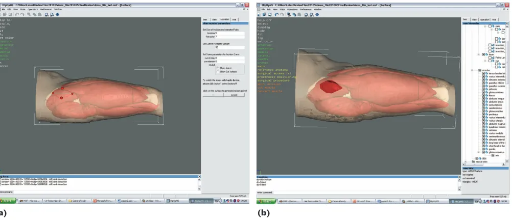
Surgical-access planning consists of a skin incision, muscle retraction, and femur head dis-location. The initial incision is defined by two reference points under force-feedback control. With the incision defined, the surgeon controls the aperture size using two additional reference points automatically created when the incision line is defined (see Figure 5).
We implemented the incision haptic render-er as a standard surface rendrender-errender-er, letting surgeons accurately locate the reference points while pro-viding them with feedback on the constraints imposed by the skin surface.
(b) (a)
Haptic world Haptic API
Haptic manager Device
manager Synchronizationmodule
Device controller
Communication manager Event
manager
Haptic engine Haptic
tools
Haptic
engine Generic
haptic renderers
Surgical procedure renderers
Left- and right-hand haptic mechanisms
Figure 4. (a) Prototype haptic desktop device. (b) Haptic rendering library architecture and interaction among the library modules.
Figure 5. (a) The surgeon selects the skin incision size and (b) views the incision aperture.
[image:6.585.44.539.63.262.2] [image:6.585.41.542.500.716.2]The skin incision and retraction is followed by the much more complex task of muscle retrac-tion, which has a higher probability of damaging muscles and other tissues. During this procedure, the surgeon introduces the retractor between the muscles and retracts one toward the edge of the skin incision. The retracted muscle is held in posi-tion while the next muscle is retracted and so forth until the head of the femur and the acetab-ulum are visible.
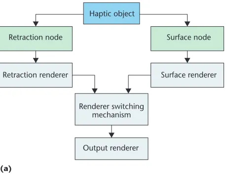
To simulate this, the haptic and visual sub-systems must cooperate within the MAF to pro-vide the correct level of synchronization. We implemented the muscle retraction haptic ren-derer, which lets the user estimate the trade-off between visibility and muscle damage during the retraction, as a combined haptic node formed from two haptic renderers (see Figure 6a). The first node represents the surface of the muscle to be retracted and is implemented as a surface hap-tic renderer permitting interaction with the mus-cle surface. The second node implements the retraction haptic model realized using a
two-spring (200 to 400 Newton meter [N/m]) model (see Figure 6b).
We tuned the spring parameters using a Finite Element (FE) analysis of muscle and actual patient data. The state of the MAF operation con-trols switching between the surface and retrac-tion models. When the femur and acetabulum are visible, the femur head can be dislocated from the socket to allow access through the aperture (see Figure 7). To let the user assess the difficulty in operating through the aperture, we generate force feedback during the dislocation.
This is modeled when a collision occurs between the femur head and the surrounding soft tissue objects (muscles and skin). To simulate the resistance caused by muscle elongation, we generate additional feedback forces from the muscles connecting the femur and ileum. We modeled each muscle as a spring/damper:
(1)
F a u a
F F
m M m m m f m
elongation i
i N
m
K d B
= ⋅ ⋅ + ⋅ ×
=
=
∑
045
(a) (b)
Surface node Retraction node
Surface renderer Retraction renderer
Renderer switching mechanism
Output renderer Haptic object
Tool before contact
Line of axes
Spring 2
Spring 1
Retraction point Split point
Figure 6. (a) The muscle retraction haptic object with the integration of the surface and retraction haptic node, and (b) the two-spring retraction haptic render showing the two spring elements’ initiation and termination points.
(a) (b)
Retractor
Head of the femur
[image:7.585.149.539.64.243.2] [image:7.585.49.279.68.247.2]IEEE MultiMedia
whereKMandBmare the specific muscle stiffness
and damping parameters, dmis the muscle
elon-gation,amis the unit vector of the muscle line of
axes, and ufis the femur bone velocity vector.
This is adequate because the rendering of the force generated by the muscle elongations is a simulation feature we added to improve realism in this operation and doesn’t affect the actual planning. To permit interactive operation during the dislocation, the system visualizes the muscle lines of axis with coloration dependent on the strain (see Figure 8a).
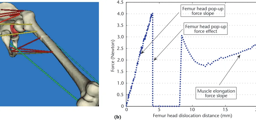
To improve the realism of a femur head dislo-cation, we implemented a pop-up effect by con-necting a strong (1000 N/m) spring—only active in close proximity to the socket’s center, between the femur head and socket centers:
(2) whereKE and BE are the pop-up stiffness and
damping parameters, pdis the femur head
dislo-cation distance vector, rdis the pop-up spring’s
active sphere radius, and ufis the femur bone
velocity vector. When the femur head disloca-tion distance becomes greater than this distance, a force discontinuity is created dropping the force to 0 Newton (N) for 40 milliseconds (see Figure 8b), creating a discontinuity that the user perceives as the femur head popping out.
Preliminary experimental results
We performed two preliminary validation experiments involving five subjects to evaluate
the multimodal benefits and effectiveness using the system shown in Figure 3. Two subjects involved in the system development were well-trained users, and three subjects had no previous system experience.
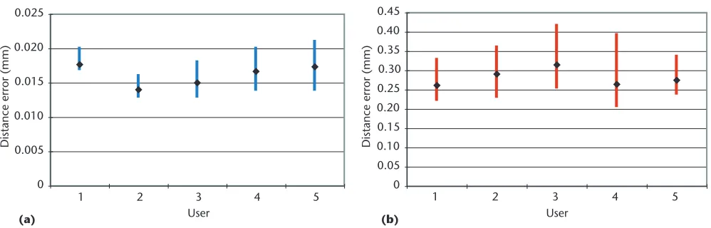
We gave each user an explanatory test sheet. Experiment 1 evaluated the benefits of force feed-back on the accuracy of defining the incision aperture. A reference aperture was defined, and the subjects were asked to execute a skin incision using the immersive multimodal interface with the haptic feedback modality active in the first case. Each subject tried to replicate the reference aperture. The users then repeated the process with the haptic modality disabled.
In the second case, with the haptic modality disabled, the system provided visual feedback (color changes) indicating contact between the device avatar and the skin. The users repeated the test five times for each case. We recorded the time required to carry out the positioning. Figure 9 gives the distance error between the position of the incision points and the position of the points of the reference incision with the haptic multi-modal interface enabled and disabled.
The users obtained significantly higher accu-racy using force feedback in this experiment. Their execution time was also considerably reduced. The average execution times we record-ed for the haptic- and nonhaptic-enablrecord-ed execu-tion were 31 and 57 seconds, respectively. This shows that integrating the haptic cues provides benefits in terms of accuracy and execution time. Another important observation is there was no significant difference in the performance among the five subjects. This initial indication
F p u p
F p
popup E d E f d d
popup d
K B r
= ⎡⎣ ⎤⎦ ⋅ + ⎡⎣ ⎤⎦ ⋅ <
=
,
0, >>rd
(b) (a)
0 5 10 15 20
0 0.5 1.0 1.5 2.0 2.5 3.0 3.5 4.0 4.5
Femur head dislocation distance (mm)
For
ce (Newton)
Femur head pop-up force slope
Femur head pop-up force effect
Muscle elongation force slope
[image:8.585.89.529.68.275.2]shows that the user effect wasn’t significant in the multimodal environment, and we achieved a good level of accuracy and usability even with minimal prior experience.
Experiment 2 demonstrated the benefits in terms of execution time using the two-handed interaction paradigm. We configured the haptic device to work in the two-handed operation mode where the left part of the device was for tool manipulation and the right for manipulating the camera of the visual scene. We asked the subjects to position and orient the retractor tool close to a predefined location between two muscles without actually performing the retraction. This task required complex manipulations of the retractor tool while simultaneously manipulating the cam-era. The subjects performed this operation five times using the haptic device, and then they repeated the same process using a standard mouse. We recorded the execution times in both cases. The time required to execute the task using a two-handed interaction was considerably reduced (on average 43 seconds) compared to that achieved with the mouse (on average 105 seconds). These results show the effectiveness of this type of interface when complex manipula-tion is necessary.
Conclusions
We’re currently evaluating the complete mul-timodal system. Our initial experiments have helped us validate the multimodal interface in the surgical access task. We might also see bene-fits from using this multimodal interface in other aspects of medical planning. We plan to exten-sively evaluate these avenues in the future to assess the usefulness of the planning procedures’ various modules. These tests will involve a broad-er selection of clinical usbroad-ers.
We’ll also work on enhancing the system’s abil-ity to address the haptic tasks requirements of other surgery procedures. These will include alter-ations or trimmings in both the system hardware (mechanical structures) and software with the incorporation of other surgical haptic renderers to form a library of surgical haptic procedures. MM
Acknowledgments
This work was supported by the Multisense European project (IST-2001-34121).
References
1. H.D. Dobson et al., “Virtual Reality: New Method of Teaching Anorectal and Pelvic Floor Anatomy,” Dis Colon Rectum, vol. 46, no. 3, 2003, pp. 349-352. 2. M.A. Spicer and M.L. Apuzzo, “Virtual Reality
Surgery: Neurosurgery and the Contemporary Landscape,”Neurosurgery, vol. 52, no. 3, 2003, pp. 489-497.
3. S. Hassfeld and J. Muhling, “Computer Assisted Oral and Maxillofacial Surgery: A Review and an Assessment of Technology,” Int’l J. Oral Maxillofacial Surgery, vol. 30, no. 1, 2001, pp. 2-13.
4. H. Handels et al., “Computer-Assisted Planning and Simulation of Hip Operations Using Virtual Three-Dimensional Models,” Studies in Health Technology and Informatics, vol. 68, 1999, pp. 686-689. 5. M. Fayad and D.C. Schimidt, “Object-Oriented
Application Frameworks,” Comm. ACM, vol. 40, no. 10, 1997, pp. 32-38.
6. F. Flippo, A. Krebs, and I. Marsic, “A Framework for Rapid Development of Multimodal Interfaces,”
Proc. 5th Int’l Conf. Multimodal interface, ACM Press, 2003, pp. 109-116.
7. M. Krokos et al., “Real-Time Visualisation within the Multimodal Application Framework,” Proc. 8th Int’l Conf. Information Visualization(IV04), ACM Press, pp. 21-26, 2004.
47
July–September 2006
Distance error (mm)
Distance error (mm)
(a) (b)
0 0.05 0.10 0.15 0.20 0.25 0.30 0.35 0.40 0.45
1 2 3 4 5
User User
0 0.005 0.010 0.015 0.020 0.025
[image:9.585.50.549.67.227.2]1 2 3 4 5
8. C.G. Schizas, B. Parker, and P.-F. Leyvraz, “A Study of Pre-Operative Planning in CLS Total Hip Arthroplasty,”Hip Int’l, vol. 6, 1996, pp. 75-81. 9. S. Nishihara et al., “Comparison of the Fit and Fill
between the Anatomic Hip Femoral Component and the VerSys Taper Femoral Component Using Virtual Implantation on the ORTHODOC Workstation,”J. Orthopaedic Science,vol. 8, no. 3., 2003, pp. 352-360.
10. M. Viceconti et al., “CT-Based Surgical Planning Software Improves the Accuracy of THR
Preoperative Planning,” Medical Eng. & Physics, vol. 25, no. 5, 2003, pp. 371-377.
11. N.G. Tsagarakis and Darwin G. Caldwell, “Pre-Operative Planning for Total Hip Replacement Using a Desktop Haptic Interface”, Proc. IMAACA 2004, DIP Univ. of Genoa, 2005, pp. 209-216 .
Nikolaos G. Tsagarakisis a research
fellow at the University of Salford, UK. He works in rehabili-tation, medical robotics, and hap-tic systems. Other research interests include novel actuators, dextrous hands, tactile sensing, and humanoid robots. Tsagarakis received his PhD in robotics and haptic technology from the University of Salford. He is a member of the IEEE Robotics and Automation Society.
Marco Petroneis a staff member
with the High Performance Systems, Visualization Group (VISIT) at the Biocomputing Competence Center (CINECA). His research interests include scientific visual-ization, biomedical applications, multimodal interaction, and the multimodal applica-tion framework (openMAF). Petrone received a degree in computer engineering from the University of Padova, Italy.
Debora Testiis a researcher at the
Laboratorio di Tecnologia Medica of the Institute of Orthopedics, Rizzoli. Her research interests include bone remodeling, osteo-porosis, femoral neck fractures, and software for computer-aided medicine. Testi has a PhD in bioengineering from the University of Bologna. She is a member of the European Society of Biomechanics.
Cinzia Zannoniis a project
man-ager with the High Performance Systems group at the Bio-computing Competence Center (CINECA) and is the coordinator of VISIT, which runs activities in scientific visualization and the development of IT services for the support of scientific communities. Zannoni received a PhD in bioengineer-ing at the University of Bologna.
John O. Gray is a professor of
advanced robotics at the University of Salford. His research interests include medical robotics, nonlin-ear control systems, precision electromagnetic instrumentation, and robotic systems for the food industry. Gray received a PhD from the University of Manchester in control engineering.
Marco G. Vicecontiis the
tech-nical director of the Laboratorio di Tecnologia Medica of the Institute of Orthopedics, Rizzoli. His research interests are in devel-oping and validating medical technology for orthopedics and traumatology. Viceconti received a PhD in bioengi-neering from the University of Florence. He is currently the secretary general of the European Society of Biomechanics and a member of the Council of the European Alliance for Medical and Biological Engineering and Science (EAMBES).
Darwin G. Caldwellis the Chair
of Advanced Robotics in the Center for Robotics and Automation at the University of Salford. His research interests include innov-ative actuators and sensors, hap-tic feedback, force-augmentation exoskeletons, dexterous manipulators, humanoid robotics, biomimetic systems, rehabilitation robotics, and robotic systems for the food industry. Caldwell received a PhD in robotics from the University of Hull. He is chair of the United Kingdom and Republic of Ireland (UKRI) region of the IEEE Robotics and Automation Society.
Readers may contact Nikolaos Tsagarakis at the School of Computer Science and Engineering, University of Salford; [email protected].