International Journal of Emerging Technology and Advanced Engineering
Website: www.ijetae.com (ISSN 2250-2459,ISO 9001:2008 Certified Journal, Volume 3, Issue 3, March 2013)
764
Performance Evaluation of ZigBee Using Multiple Input Single
Output (MISO) Architecture
Hari Kumar Choudhari
1, Dr. P. S. Patheja
2, Prof Akhilesh A Waoo
31M.Tech Student 4th Semester CSE BIST Bhopal MP 2 HOD CSE BIST Bhopal MP
3 Prof CSE BIST Bhopal MP
Abstract— ZigBee is a protocol created specifically for control of sensor networks. It Built on IEEE 802.15.4, the standard for low data rate wireless personal area networks
(WPANs).The IEEE 802.15.4 has become the preferable PAN
system for wireless sensor networks and many software and hardware platforms are based on it. The implementation and performance analysis of this standard is needed to understand the conceptual limitations of it. In this paper we have tried to improve Error rate performance of Zigbee Personal Area Network (PAN) using multiple transmitters on existing system with OQPSK modulation in AWGN channel environment. From the simulation results we have found that our proposed multiple transmitters scheme (MISO) gives quite batter results on low SNR values comparatively with the existing Single Input Single Output (SISO) approach.
Keywords— MISO, ZIGBEE, Physical Layer, OQPSK.
I. INTRODUCTION
This document is template. We ask that authors follow some simple guidelines. In essence, we ask you to make your paper look exactly like this document. The easiest way to do this is simply to download the template, and replace(copy-paste) the content with your own material.
II. PAGE LAYOUT
Zigbee is a specification for a suite of high level communication protocols based on the IEEE 802.15.4 physical and MAC layers. The specification is developed by a group of industry players, the Zigbee Alliance. Some of the commercial applications of WSNs using Zigbee are in the area of home and building automation, remote control or health care monitoring [2] IEEE 802.15.4 Standard provides for very low complexity, very low cost, very low power consumption, and low data rate wireless connectivity among low-cost devices. The data rate is high enough (250 kb/s) to meet a set of applications but is also scalable down to the needs of sensor and automation requirements (20 kb/s or below) for wireless communications. In addition, one of the alternate PHYs provides precision ranging capability that is accurate to one meter. Multiple PHYs are defined to support various frequency bands including [1]
i. 868–868.6 MHz ii. 902–928 MHz iii. 2400–2483.5 MHz
iv. 314–316 MHz, 430–434 MHz, and 779–787 MHz band for LR-WPAN systems in China
v. 950–956 MHz in Japan.
The major standardization bodies in the WSN area are the Institute of Electrical and Electronics Engineers (IEEE), the Internet Engineering Task Force (IETF) and the HART communication foundation. Notable standards and specifications are:
A.IEEE 802.15.4Standard
This standard [4] specifies the PHY and MAC layer for low-rate WPANs. Many platforms are based on this standard and other specifications, such as Zigbee and wireless HART specifications, are built on top of the standard covering the upper layers to provide a complete networking solution. Some of the main characteristics of the IEEE 802.15.4 are as follow
250 kbps, 40 kbps and 20 kbps data rates.
Two addressing modes, 16-bit short and 64-bit IEEE addressing.
CSMA-CA channel access.
Automatic network establishment by the coordinator of the network.
Power management control.
16 channels in the 2.4 GHz ISM band, 10 channels in the 915 MHz ISM band and one channel in the 868 MHz band.
DSSS-Direct Sequence Spread Spectrum
BPSK & O-QPSK Modulation
B.Wi-Fi Compatibility
The 2.4 GHz band, which ranges from 2400 MHz to 2483.5 MHz, is a worldwide band allocated to wireless LAN devices governed by IEEE 802 standards:
• IEEE 802.11 – WiFi standard • 802.15.1 – Bluetooth
International Journal of Emerging Technology and Advanced Engineering
Website: www.ijetae.com (ISSN 2250-2459,ISO 9001:2008 Certified Journal, Volume 3, Issue 3, March 2013)
[image:2.612.55.280.243.409.2]765 The above standards cover LAN and MAN carrying variably sized packets. They find the no. of channels that devices can use in the 2.4GHz band and together they appear to coexist happily. ZigBee devices can use up to 16 separate 5MHz channels (nos. 11-26) in the 2.4 GHz band, almost all the channels do not overlap with channels occupied by 802.11 and Wi-Fi network. What’s more, as considered above, ZigBee automatically retransmits data end-to-end in the event of interference. And even then, very little data is retransmitted.
Fig. 1 Zigbee Architecture
With its exclusive focus on sensors and controls, ZigBee should not be affected by similar wireless technologies with different purposes.
Yet concerns have been voiced that despite efforts made by standardisation bodies to ensure smooth coexistence, communication technologies transmitting at very different power levels could interfere with each other. Questions have in particular been raised over how Wi-Fi might affect ZigBee when both are transmitting in the same channel with Wi-Fi transmissions taking place at a much higher power rating.
C. Cheaper
Low cost for users is not only about lower power consumption. Other factors are low retail cost and low maintenance and installation costs. The 802.15.4 PHY layer was designed precisely to ensure low cost and high levels of integration. Although ZigBee’s radio design principally uses digital circuitry it does include analog stages. However, the use of direct sequence CDMA results in very simple analog circuitry that lends itself to low-cost implementation.
As observed above, 802.15.4’s MAC enables multiple topologies that are not complex and have only two basic modes of operations.
The result is low or no maintenance (particularly in residential fit-and-forget applications), while networks’ self-healing capability and node redundancy further dispenses with maintenance. The extensive use of RFDs – cheap to manufacture and maintain thanks to their inherent low functionality, low ROM and RAM – helps keeps cost down.
Further controlling cost is the ZigBee application layer. It was designed to let networks grow physically without the need for more powerful power transmitters, even when networks have very large numbers of nodes with low latency requirements.
In addition to low power consumption, the key factor in ZigBee’s low cost is, perhaps, its simplicity. By way of comparison, the number of layers in ZigBee’s protocol stack is four times less than in Bluetooth’s. Indeed, further comparison with Bluetooth can be a convenient way of highlighting some other ZigBee strong points.
D.Major Parts of the IEEE 802.15.4 WPAN
A system meeting the requirements to this standard consists of several components. The most basic is the device. Two or more devices communicating on the same physical channel constitute a WPAN. However, this WPAN includes at least one FFD, which operates as the PAN coordinator.[1]
III. LR-WPANDEVICE ARCHITECTURE
The IEEE 802.15.4 design is defined in terms of a number of blocks in order to simplify the standard. These blocks are called layers.
Each layer is responsible for one part of the standard and offers services to the higher layers.
Figure 2: IEEE 802.X Wi-Fi standard comparison
[image:2.612.325.562.508.627.2]International Journal of Emerging Technology and Advanced Engineering
Website: www.ijetae.com (ISSN 2250-2459,ISO 9001:2008 Certified Journal, Volume 3, Issue 3, March 2013)
[image:3.612.102.234.163.287.2]766 Figure 2 shows these blocks in a graphical representation, which are described in more detail in next paragraphs.
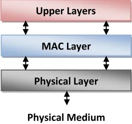
Figure 3: LR-WPAN device architecture
The upper layers, shown in Figure 3, consist of a network layer, which provides network configuration, manipulation, and message routing, and an application layer, which provides the intended function of the device. The definition of these upper layers is outside the scope of this standard [1].
A. Physical layer (PHY):
The PHY provides two services: the PHY data service and the PHY management service. The PHY data service enables the transmission and reception of PHY protocol data units (PPDUs) across the physical radio channel. The features of the PHY are activation and deactivation of the radio transceiver, ED, LQI, channel selection, clear channel assessment (CCA), and transmitting as well as receiving packets across the physical medium. The UWB PHY also has the feature of precision ranging.[1][2]
B. MAC sub layer:
The MAC sub layer provides two services: the MAC data service and the MAC management service interfacing to the MAC sub layer management entity (MLME) service access point (SAP) (known as MLMESAP). The MAC data service enables the transmission and reception of MAC protocol data units (MPDUs) across the PHY data service. The features of the MAC sub layer are beacon management, channel access, GTS management, frame validation, acknowledged frame delivery, association, and disassociation. In addition, the MAC sub layer provides hooks for implementing application-appropriate security mechanisms.
C. Power consumption considerations:
In many applications that use these standard, devices will be battery powered, and battery replacement or recharging in relatively short intervals is impractical.
Therefore, the power consumption is of significant concern. Battery-powered devices will require duty-cycling to reduce power consumption. These devices will spend most of their operational life in a sleep state; however, each device periodically listens to the RF channel in order to determine whether a message is pending. This mechanism allows the application designer to decide on the balance between battery consumption and message latency. Higher powered devices have the option of listening to the RF channel continuously.
In addition to the power saving features of the LR-WPAN system, the UWB PHY also provides a hybrid modulation that enables very simple, non coherent receiver architectures to further minimize power consumption and implementation complexity. [2]
IV. ZIGBEE FRAME STRUCTURE
The superframe is defined between two beacon frames and has an active period and an inactive period. Figure 8 depicts the IEEE 802.15.4 superframe structure.
Figure 4 - IEEE 802.15.4 Superframe Structure
The active portion of the superframe structure is composed of three parts, the Beacon, the Contention Access Period (CAP) and the Contention Free Period (CFP):
A. Beacon
The beacon frame is transmitted at the start of slot 0. It contains the information on the addressing fields, the superframe specification, the GTS fields, the pending address fields and other PAN related.
B. Contention Access Period (CAP):
The CAP starts immediately after the beacon frame and ends before the beginning of the CFP, if it exists. Otherwise, the CAP ends at the end of the active part of the superframe. The minimum length of the CAP is fixed at aMinCAPLength = 440 symbols. This minimum length ensures that MAC commands can still be transmitted when GTSs are being used. A temporary violation of this minimum may be allowed if additional space is needed to temporarily accommodate an increase in the beacon frame length, needed to perform GTS management. All transmissions during the CAP are made using the Slotted CSMA/CA mechanism.
Upper Layers
MAC Layer
Physical Layer
[image:3.612.331.564.364.424.2]International Journal of Emerging Technology and Advanced Engineering
Website: www.ijetae.com (ISSN 2250-2459,ISO 9001:2008 Certified Journal, Volume 3, Issue 3, March 2013)
767 However, the acknowledgement frames and any data that immediately follows the acknowledgement of a data request command are transmitted without contention. If a transmission cannot be completed before the end of the CAP, it must be deferred until the next superframe.
C. Contention Free Period (CFP)
The CFP starts immediately after the end of the CAP and must complete before the start of the next beacon frame (if BO equals SO) or the end of the superframe. Transmissions are contention-free since they use reserved time slots (GTS) that must be previously allocated by the ZC or ZR of each cluster. All the GTSs that may be allocated by the Coordinator are located in the CFP and must occupy contiguous slots. The CFP may therefore grow or shrink depending on the total length of all GTSs. In beacon-enabled mode, each Coordinator defines a superframe structure Figure 3 which is constructed based on:
- The Beacon Interval (BI), which defines the time between two consecutive beacon frames.
- The Superframe Duration (SD), which defines the active portion in the BI, and is divided into 16 equally-sized time slots, during which frame transmissions are allowed.
Optionally, an inactive period is defined if BI > SD. During the inactive period (if it exists), all nodes may enter in a sleep mode (to save energy). BI and SD are determined by two parameters, the Beacon Order (BO) and the Superframe Order (SO), respectively, as follows:
aBase Superframe Duration = 15.36 ms (assuming 250 kbps in the 2.4 GHz frequency band) denotes the minimum duration of the superframe, corresponding to SO=0. As depicted in Figure 3, low duty cycles can be configured by setting small values of the SO as compared to BO, resulting in greater sleep (inactive) periods. In ZigBee Cluster-Tree networks, each cluster can have different and dynamically adaptable dutycycles. This feature is particularly interesting for WSN applications, where energy consumption and network lifetime are main concerns. Additionally, the Guaranteed Time Slot (GTS) mechanism is quite attractive for time-sensitive WSNs, since it is possible to guarantee end-to-end message delay bounds both in Star and Cluster-Tree topologies.
V. RELATED WORK
International Journal of Emerging Technology and Advanced Engineering
Website: www.ijetae.com (ISSN 2250-2459,ISO 9001:2008 Certified Journal, Volume 3, Issue 3, March 2013)
[image:5.612.41.231.134.753.2]768 Fig. 5 Flow Chart
In this work we are working on the physical layer of network architecture in which we are trying to increase the error rate performance of the system by implementing multiple transmitters instead of single transmitter in existing system . The system design and simulation has been done on MATLAB environment. The flow chart of simulation procedure is given above.
VI. SIMULATION RESULTS
The simulation has been done with the MATLAB R2011b environment. During simulation we are calculating the Bit Error Rate for multiple transmitters using different iterations. The below graphs show how system efficiently works with more than single antenna.
[image:5.612.331.560.280.666.2]Fig. 6.1. BER Vs SNR performance of the system with multiple antennas and 25 iterations.
Fig. 6.2. BER Vs SNR performance of the system with multiple antennas and 50 iterations.
Start
End
Initialize Zigbee System Parameters
Set No. of Iterations (N)
i=0, i ≤ N
Generate Random Data (PSDU)
Prepare Frame (PPDU)
Convert Symbols into Chip Sequence
Modulate using OQPSK Modulator
Add AWGN Noise
Demodulate using OQPSK Demodulator
Convert Chip Sequence into Symbols
Bit Error Calculation
i = N
Mean Error Calculation
International Journal of Emerging Technology and Advanced Engineering
Website: www.ijetae.com (ISSN 2250-2459,ISO 9001:2008 Certified Journal, Volume 3, Issue 3, March 2013)
[image:6.612.60.510.74.530.2]769
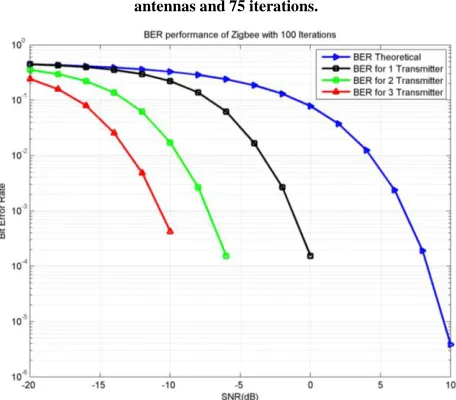
Fig. 6.3. BER Vs SNR performance of the system with multiple antennas and 75 iterations.
[image:6.612.54.288.92.309.2]Fig. 6.4. BER Vs SNR performance of the system with multiple antennas and 100 iterations.
[image:6.612.331.557.184.516.2]Fig. 6.5. BER Vs SNR performance of the system with multiple antennas and 125 iterations.
[image:6.612.55.283.326.526.2]International Journal of Emerging Technology and Advanced Engineering
Website: www.ijetae.com (ISSN 2250-2459,ISO 9001:2008 Certified Journal, Volume 3, Issue 3, March 2013)
[image:7.612.54.286.95.311.2]770
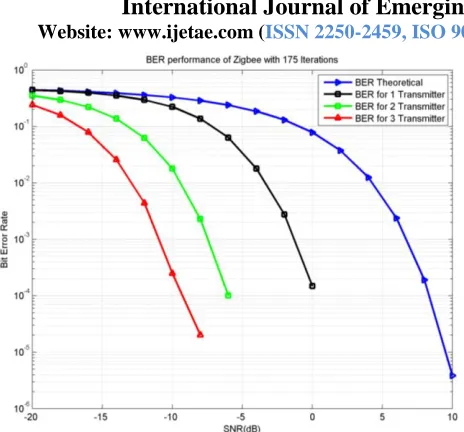
Fig. 6.7. BER Vs SNR performance of the system with multiple antennas and 175 iterations.
Fig. 6.8. BER Vs SNR performance of the system with multiple antennas and 200 iterations.
From the above results in figures from 6.1 to 6.8 it is clear that if we increase the transmitters and the transmitter size of the system the Bit Error Rate reduced significantly, and the signal power requirements also reduces which is the great thing about our proposed approach. And also shows that the if we increase the no. of repetitions of the frame our results precisely improved.
VII. CONCLUSIONS AND FUTURE WORK
From the Simulation results, the existing with 2.4 GHz band and with O-QPSK modulation works significantly with low power operations but there is always a need some improvement in the system, so here we have tried to reduce the Bit Error Rate and also the Power Requirements of the system which will be the revolution in the field of 802.15.4. Here we have increased the number of transmitters which greatly reduces the error rate of the existing system. Here we simulate system upto three transmitters but in future with the developments in the antenna technology we can increase more transmitters as our ease. The future of our proposed work will be the lowest power consumption PAN(Personal Area Network) for information sharing and network access.
REFERENCES
[1 ] J. Stankovic, I. Lee, A. Mok, R. Rajkumar, ―Opportunities and Obligations for Physical Computing Systems‖, in IEEE Computer, Volume 38, Nov, 2005.
[2 ] The Economist, ―When everything connects‖, April 28th – May 4th, 2007.
[3 ] N. Aakvaag, M. Mathiesen, and G. Thonet, ―Timing and power issues in wireless sensor networks, an industrial test case‖, In Proceedings of the 2005 International Conference on Parallel Processing Workshops (ICPPW). IEEE, 2005.
[4 ] S A Bhatti (Student), I A Glover, ―Performance Evaluation of IEEE 802.15.4 Receiver in the Presence of Broadband Impulsive Noise‖ IEEE Student Application Paper 2011.
[5 ] Minakshmi Roy, H.S. Jamadagni, ―Cancellation of Zigbee interference in OFDM based WLAN for multipath channel‖, ACEEE Int. J. on Network Security, Vol. 02, No. 01, Jan 2011. [6 ] Nilesh Shirvoikar, Hassanali Virani, Dr. R.B. Lohani, ―Performance
[image:7.612.56.285.349.541.2]