Analysis of Mixture formation and Flame Development of Diesel
Combustion using a Rapid Compression Machine and Optical
Visualization Technique
Amir Khalid
1,a, Bukhari Manshoor
2,b1,2
Automotive Research Group, Centre for Energy and Industrial Environment Studies (CEIES), Universiti Tun Hussein Onn Malaysia, Parit Raja, Batu Pahat, 86400 Johor, Malaysia.
a
[email protected], [email protected]
Key Words: Swirl Velocity, Mixture Formation, Diesel Combustion, Ignition Delay, Ignition Process, Spray, Rapid Compression Machine, Flame Pattern, Image Analysis
Abstract. Mixture formation plays as a key element on burning process that strongly affects the exhaust emissions such as nitrogen oxide(NOx) and Particulate Matter(PM). The reductions of emissions can be achieved with improvement throughout the mixing of fuel and air behavior. Measurements were made in an optically-accessible rapid compression machine (RCM) with intended to simulate the actual diesel combustion related phenomena. The diesel combustion was simulated with the RCM which is equipped with the Denso single-shot common-rail fuel injection system, capable of a maximum injection pressure up to 160MPa. Diesel engine compression process could be reproduced within the wide range of ambient temperature, ambient density, swirl velocity, equivalence ratio and fuel injection pressure. The mixture formation and combustion images were captured by the high speed camera. Analysis of combustion characteristics and observations of optical visualization of images reveal that the mixture formation exhibit influences to the ignition process and flame development. Therefore, the examination of the first stage of mixture formation is very important consideration due to the fuel-air premixing process linked with the combustion characteristics. Furthermore, the observation of a systematic control of mixture formation with experimental apparatus enables us to achieve considerable improvements of combustion process and would present the information for fundamental understanding in terms of reduced fuel consumption and exhaust emissions.
Introduction
In diesel engines, combustion progresses by nature heterogeneous. Diesel spray spontaneous ignites within short period after fuel injection. The diesel engine has undergone continues improvements through the development of engines technologies especially in controlling the combustion process in order to reduce the NOx and PM levels and also to tackle the fuel economy vehicle. The most important issue in diesel combustion is achieving sufficient rapid mixing between the injected fuel and the air in cylinder prior to ignition[1]. In this research, the new combustion concept based on the characteristics of diesel ignition and combustion is investigated focusing on fuel-air mixing with changing ambient condition. The oxidation reactions at the end of endothermic period depends on the physical process such as air entrainment, the breakup of the jet spray, and droplets evaporation [1-4].
This study investigated diesel combustion fundamentally using a rapid compression machine (RCM). A constant volume chamber with displacement of 1701.4cm3 was used to simulate actual phenomenon inside the combustion chamber with changing design parameter such as ambient condition, air motion, injection strategies and variable nozzle concept. Experimental parameters were ambient temperature and oxygen concentration, ambient density, swirl velocity, injection pressure, pilot injection and injection nozzle specifications such as nozzle hole-diameter and number of holes. Along with these parameters, a better comprehension of combustible mixtured, auto-ignition and combustion process is also needed for the optimization of diesel engines [5]. In consequence, experiment used a rapid compression machine together with the schlieren photography and direct photography methods. The detail behavior of mixture formation during ignition delay period was investigated using the schlieren photography system with a high speed digital video camera. This method can capture spray evaporation, spray interference and mixture
formation clearly with real images. Ignition process and flame development were investigated by direct photography method using a light sensitive high-speed color digital video camera. The sensitive camera could clearly capture spray ignition with extremely dark flame and observed flame development with the mixture of dark and bright flames. In this research, the observation and advanced monitoring of mixture formation and combustion flames plays an important role in-depth understanding of the fuel-air premixing, combustion process and exhaust emissions as shown in Fig. 1. The graphic shows that the flow parametric study can be used to investigate the relation between mixture formation and burning process that can give valuable information to improve and optimize the combustion process. Finally, the in-cylinder pressure data are analyzed to obtain the apparent heat release rate. The images of mixture formation and flame development are analyzed together with the heat release and expected to provide very accurate information prior to the combustion process and exhaust emissions.
Experiment Setup
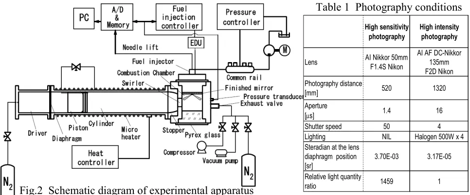
[image:2.595.100.519.242.427.2]Rapid Compression Machine. The experimental apparatus can be divided into several systems such as rapid compression machine, single-shot common rail system, data acquisition systems and exhaust emission measurement systems. The general schematic diagram of experiment apparatus is shown in Fig. 2. A free-piston type rapid compression machine (RCM) was used to simulate diesel combustion in a constant volume over a wide range of ambient temperature and pressure conditions similar to actual diesel engines. In addition, systems were added with the exhausts analyzer to observe the exhaust emissions and the in-chamber pressure data are acquired with piezoelectric pressure transducer.
Fig.2 Schematic diagram of experimental apparatus
Table 1 Photography conditions
High sensitivity photography
High intensity photography
Lens AI Nikkor 50mm
F1.4S Nikon
AI AF DC-Nikkor
135mm F2D Nikon
Photography distance
[mm] 520 1320
Aperture
[µs] 1.4 16
Shutter speed 50 4
Lighting NIL Halogen 500W x 4
Steradian at the lens
diaphragm position [sr]
3.70E-03 3.17E-05
Relative light quantity
ratio 1459 1
Flame images
Luminous intensity Geometry
- Bright flame
- Dark flame( well-mixture) - Blue flame (low luminosity) -Size/shape/ area
-Ignition point -Lift-off length -Orientation -Circularity
Schlieren images
Study criteria -Influences of mixture formation during ignition delay period
-Effects of air entrainment and oxygen concentration on ignition and burning process
In-chamber pressure Heat release rate Emissions Fuel/air input
Reducing exhaust emissions of diesel engines
Engine technologies Boost pressure
Swirl velocity Injection pressure Ambient temperature
EGR
Combustion analysis
Effects of design parameters on Mixture formation
-physical process (spray penetration) -fuel-air mixing mechanism
(atomization, evaporation) -air motion
-chemical process -endothermic period -entrainment rate
Characteristics flame parameters
Recommendation to combustion optimizations
RCM
[image:2.595.57.540.573.774.2]The spray chamber was disc type with a diameter of 60mm and a width of 20mm. Measurement were made in an optically-accessible with one of the base surfaces of the chamber was composed of pyrex glass to observe spray and flame developments, and the other side surface had an injector holder. During experiment, the fuel injection is varied by controlling the common rail system. Nevertheless, the ambient condition of the combustion chamber was controlled by the air motion and temperature. Piston (aluminum 17ST-4) motion induced air inside the chamber. The RCM has a portable swirler at intake ports which allow the amount of swirl to be varied at 10-60m/s by changing the port inclination angle controlled swirl velocity. Base swirl velocity rs was rs=19m/s in
this study.
Optical Setup
In this study, mixture formation, initial flame and burning process were examined by measuring the in chamber pressure and observation of direct photograph taken by high-speed color digital video camera (NAC, GX-1) via a quartzes window with frame speed of 10000fps. The images of mixture formation and combustion process were observed by using the direct and schlieren optical photography methods.
Direct Photography. Ignition process and flame development were investigated by direct photography method using a light sensitive high-speed color digital video camera. The sensitive camera could clearly capture spray ignition and flame development with extremely dark flame. Direct imaging can also be used to obtain information of the flame development after ignition and also as evidence in order to understand the burning process diagnostics. Furthermore, direct photograph method provides instantaneous observation of flame development and flame pattern area with real time measurement. In direct photograph technique, the optical equipment can be broadly divided into two optical setups, one is high intensity photograph and the other is high sensitivity photograph, as shown in Fig. 3. The details comparisons of the photograph condition are clearly shown in Table 1. To compensate for these differences, the camera lens which comes with the different focal length is arranged in front of high-speed camera. As shown in Fig. 3(a), images of the spatial distribution of natural flame luminosity are obtained shortly after commencement of firing operation. The high intensity images is observed with the lens (Nikon 135mm f/2D) in order to suppress the quantities for high intensity combustion flame.
Fig.3 Schematic diagram of direct photography
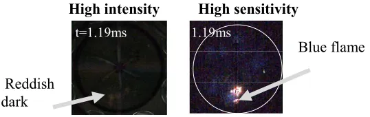
Generally, diesel combustion has a high flame luminance because of its diffusion flame. However, during ignition process, the blue flame appears first and continues with the luminous flame. In addition, the intensity blue flame or initial flame becomes more obvious and are nearly dependent of combustion parameter such as oxygen concentration and ambient density reflects the relative change in the flame development intensity. The overall flame intensity decreases with decreasing oxygen concentration and increasing ambient density. Due to the initial flame is very low luminosity, the optical set up under high intensity method cannot be performed in order to capture flame under extremely low diffusion flame. Therefore, the temporal blue flame development visualization or low luminance image is captured by high sensitivity photograph method as presented in Fig. 3(b). According to Fig. 3(b), the camera lens was used with short telephoto lenses (Nikon 50mm f/1.4) in order to capture a large amount of light especially the low flame intensity during the initial flame development. Fig. 4 compares the initial flame development images with the different direct photography method but appears in the same time period. As seen in Fig. 4, the images on the left, with high intensity photography shows the reddish dark flame. On the contrary, images on the right, with high sensitivity photography show clearly the region of blue flame. Both flames are indicator to the well-mixtured area but the high sensitivity photography providing the more clear of well-mixtured area during ignition.
Schlieren Photography. The detail behavior of mixture formation during ignition delay period was investigated using the schlieren photography system with a high speed digital video camera. The schlieren images of spray evaporation and mixture formation without ignition were detected with this system. This method can capture spray evaporation, spray interference and mixture formation clearly with real images. The optical equipments of schlieren photography are also shown in Fig. 5. The schlieren monochromes images were captured by a high-speed digital video camera (Eastman Kodak Ektapro, HS4540) with frame speed of 13500fps. In conducting these tests, special lens (Sigma 170-500mm, F5-6.3 APO) are needed due to the longer of focal length from concave mirror. The surface of injector holder that composed of base surface of the chamber was mirror finished. The principle of schlieren technique is that of introducing a Xe-light source (Ushio XS-102AA-A) and projected with concave mirror (focal length 2000mm) passing through the mirror, half mirror and quartz mirror placed in front of chamber. Here, the straight and equal intensity of light is produced by the Xe-light source. Then, the parallel light of Xe light created by concave mirror was reflected by the mirror surface. A ring edge with a diameter of 2.5 mm was used as a schlieren stop and was set at the focal point of another concave mirror. The atmosphere was filled by nitrogen gas in the case of schlieren photography.
Effects of ambient density
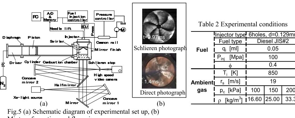
Fig. 5(a) shows the schematic diagram of a free-piston type rapid compression machine which used to simulate actual phenomenon inside the combustion chamber and the basics specifications are listed in Table 2. The charging pressure pc were changed to pc=100kPa, 150kPa and 200kPa with keeping
ambient temperature of Ti=850K. At every condition, ambient density ρ was ρ=16.6kg/m3,
[image:4.595.174.443.74.159.2]25.0kg/m3, 33.3kg/m3, respectively. Schlieren photograph indicated the detail of mixture formation was resulting from noncombustion diesel sprays which avoided by using nitrogen ambient and the direct photography technique is used to capture the flame development images, as shown in Fig. 5(b).
Fig.4 Comparison of the initial flame of diesel combustion from different direct photography method (Ignition point relation to the well-mixture area)
High intensity High sensitivity
Blue flame
Reddish dark
Fig. 6(a) compares tendencies of flame development images well correspond to the distribution of combustible mixture observed in schlieren images. In particular, at pc=100kPa (ρ=16.6kg/m3)
and 150kPa(ρ=25.0kg/m3), fuel spreads out between each spray and large amount combustible mixture is formed at the time of ignition. At pc=100kPa and 150kPa, flame is observed near the
spray centerline because of fuel is continuously injected into the spray centerline even after ignition, creates high temperature and rich atmosphereregion. However, pc=150kPa is producing larger area
of flame compares to pc=100kPa due to less formed of combustible mixture. In contrast, at
pc=200kPa (ρ=33.3kg/m3) that is high ambient density, weakens and bended the spray penetration
due to the swirl motion, fuel is mainly distributed at the center of the combustion chamber and little fuel is distributed near the chamber wall. Moreover, flame images shows the highest luminosity flame develops within center region of the chamber and possible to create locally rich combustion around chamber center. In this chamber, the condition of pc=100kPa seems to produce better
distribution of the mixture than the cases of pc=150 and 200kPa.
Fig. 6(b) shows heat release rate dQ/dt together with nozzle needle lift NL against time. According to the figure, increasing ambient density produces high heat capacity at spray boundary reflects shortens ignition delay and earlier rise of heat release rate. However, at high ambient density, increasing rate of initial heat release is gentle and combustion duration becomes long as compared with lower ambient density condition. In addition, heat release pattern related with the changes of flame pattern, are compared within the same of time at all conditions. As result, the mixture formation process may affect heat release history and flame pattern as well.
1.2ms
Schlieren photograph
[image:5.595.57.532.72.263.2]Direct photograph
Table 2 Experimental conditions
Injector type Fuel type
qi [ml] Pinj [Mpa]
φ
Ti [K] rs [m/s] pc [kPa]
ρ [kg/m3] Ambient
gas
16.60 25.00 33.3 100
850
100 150 200 19 Fuel Diesel JIS#2 0.05 6holes, d=0.129mm 0.4
Fig.5 (a) Schematic diagram of experimental set up, (b) Mixture formation and flame images
D DD
D iiiiaapaappphhh rhrrraaagagggmmmm PPPP iiiisss tstttoooonnnn
P PP PCCCC
IIIInnn jjjjeneeecc tccttteee rerrr S
S S Swwww iiiirrrr lllleee rerrr M MM Meeememmomoo rorrryyyy
A A A A///D/DDD
& & &
& iiiinnnn jjjjeeeecc tccttt iiiioooonnnn F F F Fuuuueee lllle
N NN
Neeeeeeeeddd llllede llll iiii fffftee ttt EEDEEDDDUUUU c cc coooonnn tnttt rrrroooo llll lllleee rerrr
P P P P rrrreeeessssssussuu rurrreeee
M M M M X X X
Xeee-e--- llll iiiigggghhhh tttt ssossooouuu rurrrccceceee
PPPP rrrreeee ssss ssss M M M M iiiirrrr rrrroooo rrrr
S SS
Scccchhhh llll iiiieeee rrrreeneennn ssss ttttoooopppp
H H H Haaaa llll ffff mmm iiiirmrrr rrrroooo rrrr
H H H H iiiigggghhhh ssspspeppeeeeeeedddd
v v v v iiiidddedeeeoooo ccccaamaammmeee rerrraaaa
C C C Cooononnnccaccaaavvvveeee m mm m iiiirrrr rrrroooo rrrr 1111
2 2 2 2 N NN N C C C Cooononnnccaccaaavvveveee m mm m iiiirrrr rrrroooo rrrr 2222
M M M
M iiiirrrr rrrroooo rrrr ffff iiiinnn iiiisnssshhhh C
C C Cooomommmmmmomonoonnn rrrraaaa iiii llll c
cc coooonnn tnttt rrrroooo llll lllleeee rrrr
D DD
D rrrr iiiivvvveee rerrr CCyCCy llll iiiinyy ndnndeddee rerrr CCoCCoomombmmbubbuuuss tssttt iiiioonoon cnnccchhhhaaamammbmbebbeee rrrr
(a)
t=0.97ms
1.4ms
[image:5.595.99.533.477.646.2](b)
Fig. 6 Effects of ambient density (a) mixture formation and flame development,
(b) heat release and flame pattern
0 1 2 3 Ti= 850K,rs= 19m/s
Pinj= 100MPa,qi= 0.05ml
d Q /d t M J /s
0 1 2 3 4
t ms
N
L
1.6ms 1.6ms
1.6ms
33.3kg/m3 25.0kg/m3
ρ=16.6kg/m3
(b) (a)
ρ=16.6kg/m3 τ=0.94ms
t=0.97ms 0.75ms 0.52ms
Summary
It is seen from the schlieren images that high ambient density weakens the spray penetration. The spray path is bended by the swirl motion. High ambient density resulting from the increasing of boost pressure is anticipated to influence the mixture formation during ignition delay period and burning process. As seen from the flame images, tendencies of flame distribution well correspond to the distribution of combustible mixture observed in schelieren images. This result indicates that the intensity of flame pattern is a kind of signal that tells the position where well-mixed mixture is prepared before ignition. Increasing ambient density shortens ignition delay. High heat capacity at spray boundary resulting from high density mitigates temperature drop of ambient gas, and promotes formation of combustible mixture. Consequently, it is possible to create locally rich combustion around chamber center at quite early stage of initial combustion under high ambient density condition. It is important to improve mixture formation so as to fully consume oxygen under high ambient density condition.
Acknowledgements
The author would like to express his gratitude to Prof. Dr.Yoshiyuki Kidoguchi from Power Laboratory, The University of Tokushima, Japan for his advice and guidance in this research. The authors also would like to thank the Ministry of Higher Education, Malaysia for supporting this research under the Fundamental Research Grant Scheme (FRGS) VOT.1054.
Reference
[1] Miwa, K., Ohjima, T. and Nishitani, T., "A Study of the Ignition Delay of Diesel Fuel Spray Using a Rapid Compression Machine", JSME International Journal, Series II, Vol.31, No.1, pp.166-173, 1988.
[2] Khalid, A., Yatsufusa, T., Miyamoto, T., Kawakami, J. and Kidoguchi, Y., "Analysis of Relation between Mixture Formation during Ignition Delay Period and Burning Process in Diesel Combustion", SAE Paper 2009-32-0018, pp.1-10, 2009.
[3] Khalid, A., “Effect of Ambient Temperature and Oxygen Concentration on Ignition and Combustion Process of Diesel Spray”, The International Conference on Production, Energy and Reliability (ICPER2012), 2012.
[4] Ishiyama, T., Miwa, K. and Horikoshi, O., "A Study on Ignition Process of Diesel Spray", JSME International Journal, Series B, Vol.38, No.3, pp.483-489, 1995.