Journal of Chemical and Pharmaceutical Research, 2014, 6(6):2934-2939
Research Article
CODEN(USA) : JCPRC5
ISSN : 0975-7384
Hardware and software design of food data gathering system
Kong Xiangsheng and Hu Pengfei
Department of Computer & Information, Xinxiang University, Xinxiang, China
_____________________________________________________________________________________________
ABSTRACT
In this paper, we propose a low-complexity, low-cost, low-data-rate and low-power-consumption design principles and food data gathering approach, aiming to realize an intelligent food data gathering system based on a ZigBee and RFID technology. Further, we propose several key issues that affect the practical deployment of gathering techniques in intelligent food data gathering system.
Keywords: ZigBee; food data gathering system; RFID; pH Sensor; WSN
_____________________________________________________________________________________________
INTRODUCTION
Today's agricultural information is very dynamic and turbulent. Traditional agricultural information systems have mostly been implemented upon hierarchical architectures, which are inflexible to adapt changes and uncertainties promptly. As more and more people are using the smart devices, more and more consumers can check food’s status information by smart device, next-generation agricultural information systems must be agile and adaptable to accommodate changes without significant time delays. It is essential for an agricultural information system to obtain real-time status from the distributed and dynamic agricultural environment for decision making. ZigBee, Wireless sensor network (WSN), and radio-frequency identification (RFID) technology provide an excellent infrastructure for data acquisition, distribution, and processing.
The goal of the ZigBee is to provide the consumer with ultimate flexibility, mobility, and ease of use by wireless intelligence and capabilities into everyday devices [2]. Therefore, ZigBee is suitable for food data gathering system. The IEEE 802.15.4/ZigBee standard is a popular technology in the area of low data rate, low cost, low power consumption, and security-oriented WSNs. Although the ZigBee standard is well designed, many features related to the WSNs are still challenging, especially for cluster-tree topologies where it is possible to achieve semi-deterministic behavior.
The RFID system consists of a reader and a tag and the UHF. RFID is classified into passive and active types according to the method used to obtain the energy source of the electric wave. The passive type obtains the transmission energy from the electric wave received from the reader. The active type obtains the transmission energy from the battery. The passive tag has a semi-permanent life, no battery, is inexpensive, and is suitable for short range communication. On the other hand, the active tag can be used for long range communication because the battery is built into the tag. The active RFID can provide long range data transmission because it uses different fields. The requirement for food history management systems is growing due to the increasing importance of food safety problems. The freshness of vegetable, meat, or dairy product is very important. An active RFID tag is attached to the product that requires refrigeration and the temperature/process of distribution is monitored so that product spoilage can be prevented.
sensor nodes with wireless communication capacity and computing power. It can monitor, track, perceive and cluster the various environment or the information parameters of the detection objects, and it also has the abilities of automatic control, remote monitoring, and data computation. Sensor node is equipped with integrated sensors, data processing capabilities, data gathering capabilities and short range radio communications. Sensor nodes are spread randomly over the deployment region. Sensor networks are being deployed for a wide variety of applications including sensing, tracking, monitoring. The collected data of the member nodes are processed in the head cluster before being send to the base station and after collecting the data and in the steady state phase in the shape of a packet are send to the base station in a direct way [1].
HARDWARE DESIGN OF FOOD DATA GATHERING SYSTEM
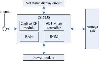
As a hardware basic unit, wireless network nodes consists of the following components: the master control module, wireless transceiver module, camera module, key control and indicate module, displays module, peripheral interface, ZigBee module and power module. In practical applications, the master equipment consists of all parts except display module; a wireless route not includes cameras and display interface. User terminal not include cameras module. Hardware Design of wireless sensor networks based on ZigBee in this paper consists of a sensor module, a transmission module, a microprocessor module and a display module (shown in Figure 1).
Figure 1. Hardware Structure of ZigBee
ZigBee Module
ZigBee's general characteristics include use of dual PHY (2.4 GHz and 868/915 MHz) with Data rates of 250 Kbits/s (@ 2.4 GHz), 40 Kbits/s (@ 915 MHz) and 20 Kbits/s (@ 868 MHz). The protocol is optimized for low duty cycle applications (<0.1%) [3]. CSMA-CA channel access yields high throughput and low latency for low duty cycle devices like sensors and controls. It also provides for an optional guaranteed time slot for applications requiring low latency as well as for low power usage with battery life ranging from multi-month to years.
ZigBee allows for multiple topologies including star, peer-to-peer and mesh, and is a full handshake protocol for transfer reliability with a typical range of 50m (5-500m based on environment). ZigBee uses spread-spectrum technologies to avoid multi-path fading and increase robustness. This approach allows for improved signal immunity in the presence of radio interference.
The IEEE 802.15.4 standard defines two PHYs representing three license-free frequency bands that include sixteen channels at 2.4 GHz, ten channels at 902 to 928 MHz, and one channel at 868 to 870 MHz. The maximum data rates for each band are 250 Kbits/s, 40 Kbits/s and 20 Kbits/s, respectively. For the 2.4 GHz PHY, the standard specifies how the data coding, spreading and modulation must be performed. Starting from the raw baseband bit stream, bits are examined by groups of four bits. Each four-bit sequence is mapped to one symbol out of 16 possible symbols. Each symbol is in turn mapped to a 32-chip sequence. These sequences are pseudo-random and they are nearly orthogonal. For commercial applications, ZigBee (IEEE 802.15.4) in particular has great potential in the area of wireless sensor networks, and ZigBee networks can incorporate a variety of topologies including Wireless Sensor Network (shown in Figure 2).
Sensor Module
The farmland information acquisition and transmission system collects the humidity, temperature and light intensity data information of the farmland. Due to the monitored area in the farmland and the conditions are relatively poor, there are many uncontrollable factors. Therefore, it is needed to consider the various factors when selects suitable sensor. The sensor should have excellent anti-interference, and be waterproof and heat resisting. It also should be small in size and easy to integrate, and low power to extend the service life. In conclusion, after analysis and comparison of various sensors, the SHT10 temperature and humidity sensor and the TSL2561 light intensity sensor are selected to measure the temperature, humidity and light intensity of the farmland environment respectively [4].
Microprocessor Module
[image:3.595.209.410.262.385.2]In this paper, MEGA128 as a microcontroller, it has a variety of enhanced power management mode, in standby mode, the current consumption is only 0.1 microampere, and can work normally from 2v to 5.5v. And MEGA128 suit for battery-driven, have 2 Synchronous serial port supporting SPI and I2C, 2 USART Asynchronous serial port supporting LIN protocol and 64KB flash. Processing capacity can meet the system requirements of the gating. The diagram of gateway node with ATmega128 is shown in Figure 3.
Figure 3. Gateway Node with ATmega128
Transmission Module
A possible way to save resources is the improvement of data transmission. In a wireless sensor network, data is transmitted together with its meta information resulting in relatively big messages; sometimes including redundant information (e.g. data source). Those messages need more resources, especially energy, for transmissions due to long periods of full radio activity.
RF transceiver chip have amount of type and quantity, 433MHz, 868MHz and 2.4GHz are its operating band, the 2.4GHz is used by ZigBee [5]. Currently, Chipcon, Freescale and other companies are focused to develop chip working at 2.4GHz for ZigBee. Choose the ideal wireless transceiver chip can reduce development effort and shorten the development cycle, reduce costs, bring products to market faster considering the cost and other factors. In this paper, we choose the wireless transceiver chip MC13192 of Freescale company. MC13192 requires minimal peripheral components, including the oscillator clock circuitry, the RF input/output matching circuit and microcontroller interface circuit. The chip local oscillator signal is provided either by external active crystal or by internal circuitry. Oscillator signal of internal circuitry need the external crystal oscillator and two load capacitors, the capacitance depends on the crystal frequency and the input capacitance and other parameters.
Power Module and Others
The sensor nodes can be powered from energy storage devices or by energy scavenging. The former technique employs a variety of tiny batteries made up of thin films of vanadium oxide and molybdenum oxide. The battery supplies power to the complete sensor node. It plays a vital role in determining sensor node lifetime. The amount of power drawn from a battery should be carefully monitored. Sensor nodes are generally small, light and cheap, the size of the battery is limited. AA batteries normally store 2.2 to 2.5 Ah at 1.5 V.
The sensor node consumes power for sensing, communicating and data processing. More energy is required for data communication than any other process. The energy cost of transmitting 1 Kb a distance of 100 meters (330 ft) is approximately the same as that used for the execution of 3 million instructions by a 100 million instructions per second/W processor. Power is stored either in batteries or capacitors. Batteries, both rechargeable and non-rechargeable, are the main source of power supply for sensor nodes. They are also classified according to electrochemical material used for the electrodes such as NiCd cadmium), NiZn zinc), NiMH (nickel-metal hydride), and lithium-ion.
Current sensors are able to renew their energy from solar sources, temperature differences, or vibration. Two power saving policies used are Dynamic Power Management (DPM) and Dynamic Voltage Scaling (DVS) [7]. DPM conserves power by shutting down parts of the sensor node which are not currently used or active. A DVS scheme varies the power levels within the sensor node depending on the non-deterministic workload. By varying the voltage along with the frequency, it is possible to obtain quadratic reduction in power consumption.
SOFTWARE DESIGN OF FOOD DATA GATHERING SYSTEM
Wireless sensor networks can be divided into centralized and distributed system. In a centralized system a single element is responsible for gathering and processing data. So, all components of the system are connected to this single element. In a distributed control system the connections between nodes and the information processing is distributed among the system components.
Sensor Nodes
A sensor node, also known as a mote is a node in a wireless sensor network that is capable of performing some processing, gathering sensory information and communicating with other connected nodes in the network. A mote is a node but a node is not always a mote.
Sensor nodes can collect and filtration data actively, but also can receive and execute the coordinator instruction. The sensor node was to have an x and a y coordinate the idea of using a structure. The structure members consisted of the node identification number (nodeID) as well as the X-coordinate (x_co) and Y-coordinate (y_co).
To get an ID number and set of coordinates for each of the one hundred sensor nodes, the use of a for loop was used. Also each node and its information were stored in an array of the structure.
for (i=1 ; i<=no ; i++){
x_coordinate = Math.random() * x_co; y_coordinate = Math.random() * y_co; nodeID[i] = i;
x[i] = xco; y[i] = yco; }
In the "for" loop, "no" used as number of nodes in the network area. Also, the coordinates are coded to exceed the network area which is 10m x 10m. The results of this coding are displayed with two resources in simulation result. The first is the output of the program showing the node ID as well as the random generated x and y coordinates.
Software Design
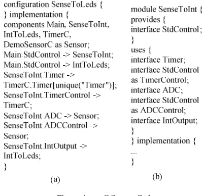
Figure 4. nesC Source Code
A nesC component exposes a set of interfaces. An interface consists of a set of methods. A method is known as either a command or an event. The component implement that provides methods and expects other components to implement that uses methods [8]. A nesC component is either a configuration that contains a wiring of other components, or a module that contains an implementation of its interface methods. A TinyOS program consists of a set of nesC components, where the top-level file that describes the application is a nesC component that exposes no interface methods.
Figure 4a shows a TinyOS program called SenseToLeds that displays the value of a photosensor in binary on the LEDs of a mote. SenseToLeds contains a wiring of the components Main, SenseToInt (shown in Figure 4b), IntToLeds, TimerC, and DemoSensorC. These components are just a few of the nesC components that are available in the TinyOS library.
Data Records are constructed in the following way: Periodically the sensor node’s hardware sends out a read command to its sensor board [9]. This read command is addressed to all connected sensors on the previously specified sensor board. In return sensors answer with their individually measured values. Depending on the latency of the network the order of incoming values vary from the order of read commands. In order to ensure the correct value order in the resulting Data Record each sensor needs to be associated with its respective Field ID, Enterprise ID, and Field Length. The implemented bidirectional interface IPFIXDataSampler supports this design. Each sensor is linked to exactly one IPFIXDataSampler (shown in Figure 5). If a node enters the established wireless sensor network, the rest task is the announcement of the Template Record used, followed by the Data Records after data acquisition.
Figure 5. IPFIX Data Sampler Source Code
Data gathering Algorithms
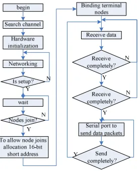
sensor application, it is not important whether a data aggregation is performed within the node itself or by a neighboring node. However, communication directed to data sinks has to be minimized since data sinks are usually located far away. It begins to work first. The main task of coordinator is to organize ZigBee network, allow the sensor nodes to join the network, bind the sensor nodes and send the collected data to the server. An example for a cooperative algorithm is location determination by triangulation [11]. This algorithm needs at least measurements from three different nodes. Computed positions then can be used for addressing or routing. The procedure flow of coordinator is shown in Figure 6.
Figure 6. The procedure flow of Monitor
CONCLUSION
In this paper, we proposed the food data gathering system that managers and consumers can check the freshness of food. Proposed system consists of temperature sensor, humidity sensor, pH sensor, reader, server and dual frequency smart RFID tag with 1.56MHz and 900MHz. To validate the effectiveness of the proposed system, we were gathering the freshness of milk by the environmental. The freshness of milk can be confirmed through pH at 4°C, 13°C and 22°C. pH of fresh milk is 6.5 to 6.9. And spoiled milk is fewer than 6.5. We obtained the model equations based on the experimental results.
REFERENCES
[1]Haiyan Liu; Jiahua Wei; Zenggang Xiong; Guangqian Wang. AISS, 2012, 4(23), 531 - 539. [2]Qiang Wang; Feng Yang. AISS, 2012(12), 152 - 159.
[3]Yang Lvqing. JCIT, 2012(15), 400 - 408.
[4]Li-feng Wei; Bing-mei Zhao. IJACT, 2013(7), 497 - 504. [5]Yu Hao. AISS, 2013(7), 1037 - 1043.
[6]Chel-Rim Choi; Young-Jae Song. IJACT, 2012(5), 240 – 248.
[7]Trimurti Lambat; Sujata Deo; Tomleshkumar Deshmukh; Journal of Chemical and Pharmaceutical Research,