PI HYSTERESIS CURRENT CONTROL TECHNIQUE FOR THREE PHASE
INDUCTION MOTOR BY USING MATLAB AND ARDUINO
FAIZUL RIZAL B MOHAMED TAZUDIN
A project report submitted in partial
fulfillment of the requirement for the award of the Degree of Master Of Electrical Engineering
Faculty of Electrical Engineering Universiti Tun Hussein Onn Malaysia
ABSTRACT
ABSTRAK
CONTENTS
TITLE i
DECLARATION ii
ACKNOWLEDGEMENT iii
ABSTRACT iv
CONTENTS vii
LIST OF FIGURE xi
LIST OF TABLE xv
LIST OF SYMBOLS AND ABBREVIATIONS xvi
CHAPTER 1:
INTRODUCTION 1
1.1 PROJECT BACKGROUND 1
1.2 PROBLEM STATEMENT 3
1.3 OBJECTIVE THESIS 4
CHAPTER 2:
LITERATURE REVIEW 5
2.1 ELECTRIC MOTOR 5
2.2 INDUCTION MOTOR 5
2.2.1 ADVANTAGES OF INDUCTION MOTOR 7 2.2.2 DISADVANTAGES OF INDUCTION MOTOR 7
2.3 INVERTER 8
2.3.1 THREE PHASE PWM INVERTER 8 2.3.2 VOLTAGE SOURCE INVERTER (VSI) 12
2.3.3 ADVANTAGES OF INVERTER 13
2.3.4 DISADVANTGES OF INVERTER 13
2.4 VARIOUS CONTROL ALGORITHMS FOR A THREE PHASE
INDUCTION MOTOR. 13
2.4.1 PID CONTROLLER 14
2.4.2 HYSTERESIS CURRENT CONTROLLER (HCC) 15 2.4.3 FUZZY LOGIC CONTROLLER (FLC) 18
2.5 PROPOSED CONTROLLER 19
CHAPTER 3:
CONTROLLER DESIGN AND DEVELOPMENT 25
3.1 BLOCK DIAGRAM OF THE PROJECT 25
3.2 THE PROJECT FLOWCHART 27
3.3 HARDWARE DESIGN 28
3.3.1 CURRENT SENSOR DESIGN 28
3.3.2 INVERTER DESIGN 31
3.3.3 GATE DRIVER DESIGN 34
3.4 PI AND HYSTERESIS (PIH) CONTROLLER DESIGN BY
MATLAB SIMULNIK 36
3.4.1 PI CONTROLLER 37
3.4.2 HYTERESIS CONTROLLER 38
3.4.3 SIMULINK MODEL OF CURRENT CONTROLLER 40
CHAPTER 4:
RESULT AND DATA ANALYSIS: 43
4.1 SIMULATION RESULT AND ANALYSIS 44
4.2 EXPERIMENTAL TEST 50
4.2.1 OPEN LOOP CONTROL TEST 50
CHAPTER 5:
CONCLUSIONS 59
5.1 DISCUSSION AND CONCLUSION 59
5.2 FUTURE WORKS 60
REFERENCES 62
APPENDIX A 65
APPENDIX B 67
APPENDIX C 70
APPENDIX D 71
LIST OF FIGURE
2.1 Three phase induction motor. 6 2.2 Full bridge voltage source inverter 9 2.3 Three phase inverter using power transistor 9
2.4 Typical PWM waveform 9
2.5 PWM 10
2.6 The output phase and line voltage from inverter 11
2.7 A three phase VSI 12
2.8 Block diagram of PID controller in a feedback loop 15 2.9 Principle of hysteresis band current controller 15 2.10 Conventional hysteresis inverter control method 16 2.11 Control block diagram for HBPWM 17 2.12 PI hysteresis current controller block diagram 20
2.13 Arduino Uno controller 23
3.2 Project flowchart 27
3.3 20Amps current transformer 29
3.4 The schematic diagram for current sensor 29 3.5 The characteristics of 20Amps current transformer 30 3.6 Schematic diagram of three phase inverter 31 3.7 Hardware design of three phase inverter 31
3.8 MOSFET terminal 33
3.9 The schematic diagram of gate driver 34 3.10 Hardware design of gate driver 35 3.11 PIH current controller block diagram in Matlab Simulink
design 36
4.3 The process of input and output ADC-DAC converter 45 4.4 The input of reference current for each phase A, B and C at
1.2 amp 46
4.5 Relationship between line and reference current at phase ‘A’
with compare to saw tooth 47
4.6 Relation between line and reference current at three phase line
‘A’, ‘B’ and ‘C’ with compare to saw tooth 47 4.7 Output PWM signal at gate driver (voltage vs time) 48 4.8 6 pulse PWM signal produce at inverter (voltage vs time) 48 4.9 Voltage output ac sinusoidal waveform of RL load 49 4.10 Open loop controller circuit 50
4.11 General Open loop circuit. 51
4.12 Measured output voltage waveform at current sensor using
proposed PIH controller at Phase ‘A’, ‘B’ and ‘C’ 51
4.13 The output PWM signal at gate driver at phase ‘A’, ‘B’ and ‘C’ 53
4.14 The output PWM signal at inverter at phase ‘A’ 53
4.15 Matlab Simulink model for closed loop PI hysteresis controller 54
4.16 Measured output voltage waveform at current sensor using proposed PIH controller at phase ‘A’, ‘B’ and ‘C’ inject at
4.17 Measured output voltage waveform at current sensor using proposed PIH controller at phase ‘A’, ‘B’ and ‘C’ inject at
0.2 amp 56
4.18 Measured output voltage waveform at current sensor using proposed PIH controller at phase ‘A’, ‘B’ and ‘C’ inject at
0.3 amp 56
4.19 PWM signal output generate at gate driver at phase ‘A’, ‘B’
and ‘C’. 57
LIST OF TABLE
2.1 The summary of the Arduino Uno 21 2.2 The specification of Arduino Uno 22 3.1 List of components for the current sensor 29 3.2 List of components for three phase inverter 32 3.3 Component lists to develop and construct a gate driver 35 4.1 The measurement of line current using PIH controller base on
reference current given. 52
LIST OF SYMBOLS AND ABBREVIATIONS
V - Voltage DC - Direct current AC - Alternating current
Vac - Alternating current voltage VSI - Voltage source inverter CSI - Current source inverter
PID - Proportional integral derivative PWM - Pulse width modulation
DTC - Direct torque ratio USB - Universal serial bus
CHAPTER 1
INTRODUCTION
1.1 PROJECT BACKGROUND
The electric motor system has always a three-closed-loop structure that includes position loop, speed loop and current loop. The current control loop is the inner one, and plays an important role to the performance of the whole system. The main task of the current controller (CC) is to force the actual current to follow the command current from the speed loop. According [1] gave an excellent review of the current control techniques, and classified them into two main groups: linear and nonlinear. Hysteresis current control (HCC) nonlinear current control has many advantages such as simple structure, fast dynamic response, robustness to the variance of load parameters, and being implemented easily [1,2,3]. However, current control switching frequency is variable in a wide range, and the frequency may be very high which is the main disadvantage of HCC is variable in a wide range, and the frequency may be very high which the main disadvantage of HCC.
with an AC motors. However, with the emergence of thyristors, Mosfets, Igbt’s and the continued development in semiconductor devices, induction motors are also now being used for such applications.
Due to advances of power electronics and vector control technologies, the induction motor drives has become popular and gradually taken the place of DC motor drives [5]. The various methods for the control of output voltage of inverters are external control of AC output voltage, external control of DC input voltage and internal control of inverter within the inverter itself [6]. The later is the most efficient method where its inverter is able to receive PWM signals to correct the current error. Therefore to generate this PWM signal, this thesis proposed to design a combination of passive and adaptive controller known as PI and Hysteresis (PIH) current control to overcome these limitations. The use of this hybrid controller because PI controller is a linear systems and can measure an average current error at each calculation cycle, and calculate an average inverter output voltage that corrects this error. Meanwhile, hysteresis controller is a non linear system and its can measured current to control the switching state of inverter. This controller also has many advantages such as fast deadbeat transient response, simplicity, insensitivity to load parameter variations, and direct over current protection [7]. Besides that, this thesis also using a current control technique because in many motor applications the motor current may lag the supply voltage due to the inductance in the circuit and it is often desirable to control the current directly, rather than the voltage, so that to obtain more precise or faster control of the current and hence the torque. . In this case a current transformer is used to monitor the current. The difference between the actual and reference currents is used in a high gain feedback loop to provide the necessary current regulation. Current control is particularly important for induction motors to protect the motor from excessive start up currents [8].
The PWM principle and PIH controller is discussed in detail and description of modeling of PIH controller is design in Matlab / Simulink. By using Simulink in Matlab users are able to create algorithms for their desired control system. Meanwhile Arduino controller has been chosen because Arduino provides a platform that helps users to understand the workflow for designing an embedded system without using manual programming.
1.2 PROBLEM STATEMENT
1.3 OBJECTIVE PROJECT
The objectives of this project are listed as follows:
i. To develop the combination of PID and hysteresis control for current controller technique on induction motor.
ii. To design and simulate the PI and hysteresis control approach by using MATLAB Simulink and interfacing with target installer, Arduino Uno.
iii. To implement and test hardware the performance controller design, inverter and measure the output of induction motor and interfacing with Arduino kit.
1.3 SCOPE OF PROJECT
In this project the scope of work will be undertaken in the following four developmental stages:
i. Study of the control system of induction motor for current control based on PI hysteresis control
ii. Perform simulation of PI hysteresis control. This simulation will be carried out on MATLABplatform with Simulink as it user interface.
iii. To develop the PI hysteresis program on the Arduino to control the three phase induction motor.
CHAPTER 2
LITERATURE REVIEW
2.1 ELECTRIC MOTOR
An electric motor is an electromechanical device that converts electrical energy to mechanical energy. This mechanical energy is used for, for example, rotating a pump impeller, fan or blower, driving a compressor, lifting materials etc. Electric motors are used at home (mixer, drill, and fan) and in industry. Electric motors are sometimes called the “workhorses” of industry because it is estimated that motors use about 70% of the total electrical load in industry. The motor can be divided into three types. There are DC motor (separately excited, series, shunt), AC motor (induction and synchronous motor) and Special motor (stepper motor, reluctance motor, universal motor) [4]. All of them have advantages and disadvantages compare to each other.
2.2 INDUCTION MOTOR
The simplest of all electric motors is the squirrel-cage type of induction motor used with a three-phase supply. The stator of the squirrel-cage motor consists of three fixed coils of copper or aluminum wire wound within insulated slots. The rotor consists of a core in which are imbedded a series of solid conductors arranged in a circle around the shaft and parallel to it. With the core removed, the rotor conductors resemble in form the cylindrical cages once used to exercise pet squirrels, hence the name 'Squirrel Cage Motor'. Three-phase current flowing in the stationary stator windings generates a rotating magnetic field, and this field induces a current in the conductors of the cage. The magnetic reaction between the rotating field and the current-carrying conductors of the rotor makes the rotor turn. If the rotor is revolving at exactly the same speed as the magnetic field, no currents will be induced in it, and hence the rotor will not turn at a synchronous speed. In operation, the speeds of rotation of the rotor and the field differ by about 2 to 5 percent. This speed difference is known as slip.
2.2.1 ADVANTAGES OF INDUCTION MOTOR
i. Able to connect directly to the AC source ii. Easy to program for its various uses iii. Low maintenance cost
iv. Durability v. Flexible design vi. Ruggedness
vii. Speed control is expensive viii. Inability to operate at low speeds.
2.2.2 DISADVANTAGES OF INDUCTION MOTOR
i. Low starting torque
ii. Have poor starting torque and high have in rush currents
iii. Induction motors always operate under lagging power factor and during light load conditions they operate at very worst power factor (0.2 to 0.4 lagging). Some of the disadvantages of poor power are increase in I2R losses in the system, reduction in the efficiency of the system. Hence some power factor correction equipments such as static capacitor banks should be placed near to these motors to deliver the reactive power to them.
2.3 INVERTER
Inverters provide a controlled alternating current (AC) supply from a DC or AC source. There are two main classes of applications:
i. Providing a fixed output from a variable source
Inverters designed to deliver regulated AC mains power from sources which may have a variable input voltage (either AC or DC) or in the case of AC input power, a variable frequency input. Such applications may include emergency generating sets, uninterruptible power supplies (UPS) or distributed power generation from wind and other intermittent resources. All must deliver a fixed output voltage and frequency to the load since the applications expect it and may depend on it.
ii. Providing a variable output from a fixed source
On the other hand, many applications require inverters to accept a fixed AC voltage and frequency from the mains and to provide a different or variable voltage and frequency for applications such as motor speed control. .
2.3.1 THREE PHASE PWM INVERTER
Figure 2.2: Figure 4: Full bridge voltage source inverter
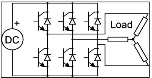
Figure 2.3: A three phase inverter using power transistors.
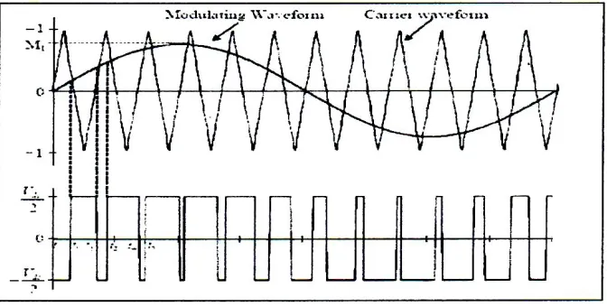
[image:24.612.154.498.248.388.2]Figure 2.4: Typical PWM waveform
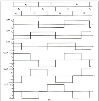
[image:25.612.162.498.347.517.2]Figure 2.6: The output phase and line voltages from the inverter.
The amplitude of the output wave is determined by the level of the DC supply voltage to the inverter block but it can be varied by thyristor (SCR) control of the rectifier circuit to provide a variable voltage at the DC link.
Instead of transistor switches, the inverter may use MOSFETs, IGBTs or SCRs.
Free-wheeling diodes connected across the transistors to protect them from reverse bias inductive surges due to motor field decay which results when the transistors turn off by providing freewheeling paths for the stored energy.
2.3.2 VOLTAGE SOURCE INVERTER (VSI)
Generally there were two types of inverter, named as Voltage Source Inverter and Current Source Inverter. Voltage waveform is the independently controlled AC output in the VSI topologies. Meanwhile, in CSI topologies, the independently controlled AC output is a current waveform. In this thesis, VSI was selected as inverter that used as study. VSI can be further divided into three categories which are PWM Inverter, Square Wave Inverter and Single-phase Inverters with Voltage Cancellation. The structure of VSI is more widely used in the industrial application due to the voltage source requirement.
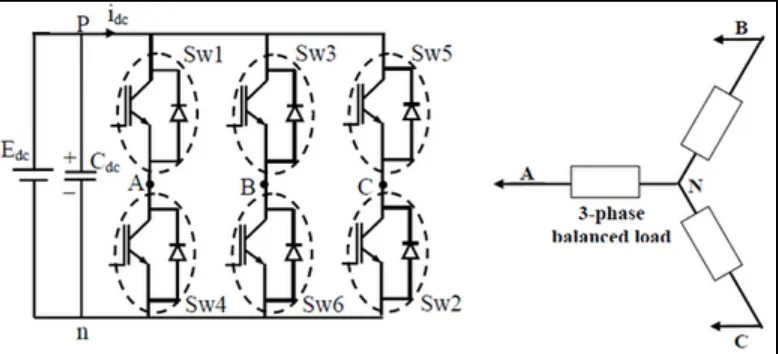
[image:27.612.134.523.404.581.2]Three phase DC/AC VSI schematically shown in Figure 2.7, are now used extensively in motor drives, active filters and unified power flow controllers in power system and interrupted power supplies to generate controllable frequency and AC voltage magnitudes using various pulse width modulation (PWM) strategies [10].
2.3.3 ADVANTAGES OF INVERTER
The advantage of inverter is to reduce the consumption of power by converting direct current (dc) to alternating current (ac). This alternated power can be maintained in any frequency or voltage with the use of an appropriate transformers, circuits and switches to support the electrical equipments at home and office.
2.3.4 DISADVANTAGES OF INVERTER
i. Not ideal for inductive AC and motor loads
ii. Sensitive electronics devices can be damaged by poor waveforms.
2.4 VARIOUS CONTROL ALGORITHMS FOR A THREE PHASE
INDUCTION MOTOR.
2.4.1 PID CONTROLLER
Proportional-Integral-Derivative (PID) controller is well known for its simplicity [11]. A PI controller is a common instrument used in industrial control applications. A PID controller can be used for regulation of speed, temperature, flow, pressure and other process variables. The PI is stand from combination of three elements, that known as proportional, integral and derivative. Defining ( ) as the controller output, the final form of the PID algorithm is:
( ) = ( ) = ( ) + ∫ ( ) + ( ) (2.1)
= proportional gain, a tuning parameter. = integral gain, a tuning parameter.
= derivative gain, a tuning parameter. = error.
= time or instantaneous time.
The theory of proportional is the error is multiplied by a negative (for reverse action) proportional constant P, and added to the current output. P represents the band over which a controller's output is proportional to the error of the system.
For integral, the error is integrated (averaged) over a period of time, and then multiplied by a constant I, and added to the current control output. I represent the steady state error of the system and will remove measured value errors.
Figure 2.8: A block diagram of a PID controller in a feedback loop.
2.4.2 HYSTERESIS CURRENT CONTROLLER
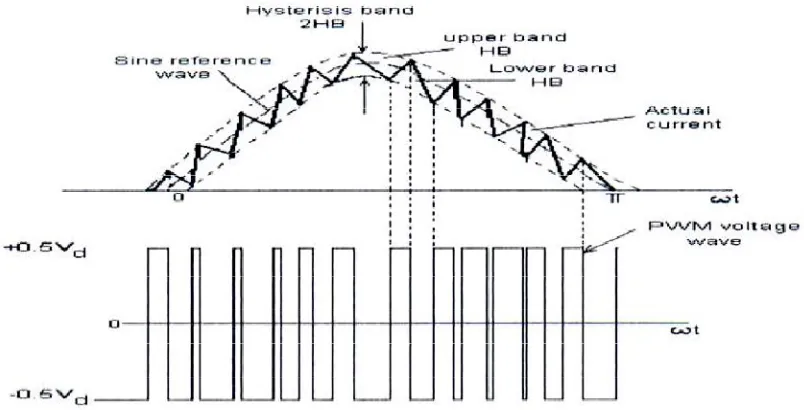
The hysteresis is basically an instantaneous feedback current control method of PWM where the actual current continually tracks the command current within a specified hysteresis band [12].
[image:30.612.130.532.446.651.2]The Figure 2.9 above explains the operation principle of HBPWM for a half bridge inverter. The control circuit generates the sine reference current wave of desired magnitude and frequency, and it is compared with the actual phase current wave. As the current exceeds a prescribed hysteresis band, the upper switch in the half-bridge is turned off and the lower switch is turned on. As a result the output voltage transitions from +0.5V to-0.5V, and the current starts to decay. As the current crosses the lower band limit, the lower switch is turned off and the upper switch is turned on. The actual current wave is thus forced to track the sine reference wave within the hysteresis band by back- and-forth (or bang-bang) switching of the upper and lower switches. The inverter then essentially becomes a current source with peak to peak current ripple, which is controlled within the hysteresis band irrespective of vd fluctuation.
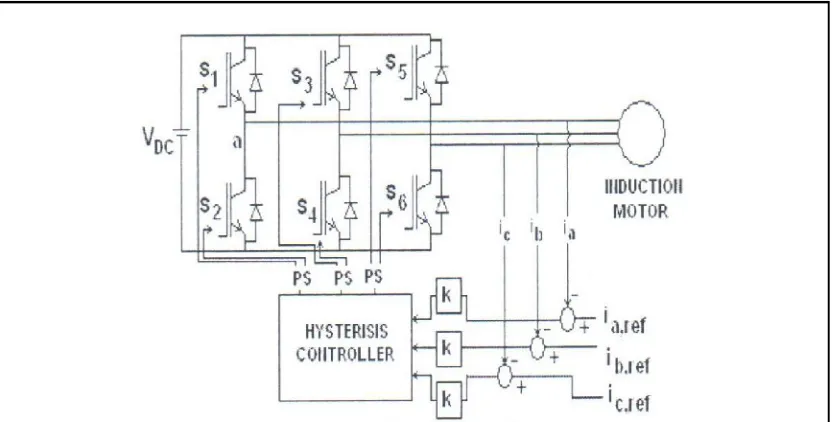
[image:31.612.117.533.486.697.2]The hysteresis band inverter control method is shown in the Figure 2.10 below. The inputs to the HBPWM controller are three phase current errors and the outputs are the switching patterns to the PWM inverter. K in the Figure represents the normalization factor and is used for the purpose of scaling the current error input to the HBPWM controller. PS is the pulse separation circuit for the separation of pulses to the IGBTs in the upper and lower leg of the inverter [13].
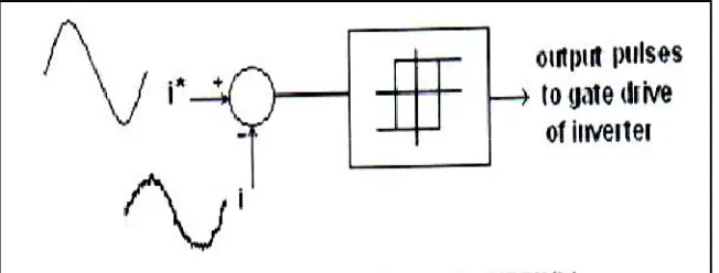
The hysteresis current controller gives output pulses to the inverter according to [14]; | im,ref – im | < ε keeps the output pulse at the same state, iref – im > ε let output pulse = 1 (high). , iref – im < -ε, let output pulse = 0 (low), where m = a, b, c phase meanwhile ε is the hysteresis band.
The algorithm for this scheme is: im, ref (t) = im, ref sin (wt)
Upper band iu = im, ref (t) + ∆i (2.2) Lower band i1 = im, ref (t) - ∆i (2.3) Where ∆i = hysteresis band limit.
If im > iu , Vmo = - Vdc / 2 (2.4) If im < iu , Vmo = Vdc / 2 (2.5)
Else, maintain the same state. Where m = a, b, c phases, i is load current and Vdc is the link voltage of the inverter [12].
Figure 2.11: Control block diagram for HBPWM
2.4.3 FUZZY LOGIC CONTROLLER
Fuzzy Logic is a problem-solving control system methodology that lends itself to implementation in systems ranging from simple, small, embedded micro-controllers to large, networked, multi-channel PC or workstation-based data acquisition and control systems. It can be implemented in hardware, software, or a combination of both. Fuzzy Logic provides a simple way to arrive at a definite conclusion based upon vague, ambiguous, imprecise, noisy, or missing input information. Fuzzy Logic incorporates a simple, rule-based IF X AND Y THEN Z approach to a solving control problem rather than attempting to model a system mathematically. The FL model is empirically-based, relying on an operator's experience rather than their technical understanding of the system.
According [16] produced a thesis on Fuzzy Logic Speed Control of Three Phase Induction Motor Drive where the thesis presents an intelligent speed control system based on fuzzy logic for a voltage source PWM. Using traditional indirect vector control system of induction motor introduces conventional PI regulator in outer space loop and PI proved that the low precision of the speed regulator debases the performance of the whole system. This problem is overcome by introducing fuzzy set controller theory. From their results, they have confirmed that the fuzzy logic controller has very good dynamic performance and robustness during transient period and sudden loads.
Thesis [18], presented a thesis on fuzzy logic control for a dc motor. From their results they concluded that by using fuzzy logic controller produces a smooth speed control with less overshoot and no oscillations, variations of reference speed attention
2.5 PROPOSED CONTROLLER
For this thesis, PI hysteresis controller has selected to be a controller because basically this controller is an instantaneous feedback current control method of PWM where the actual current continually tracks the command current within a specific hysteresis band [18]. Besides that, the advantages of this controller because of its simple implementation, fast transient response, direct limiting of device peak current and practical insensitivity of dc link voltage ripple that permits a lower filter capacitor.
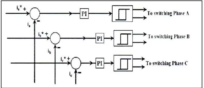
PI controller technique is chosen as to combine with hysteresis current control because to overcome undesirable drawback of classical hysteresis current controller. The input of PI controller is an error in the current between the reference current and motor current for each phase as shown in Figure 2.11 below. The proportional gain is used to improve the rise time and integral gain is used to eliminate the steady state error. This parameter can be deduced by many methods such as, trial and error, Ziegler Nicholas method and internal model control [19].
Figure 2.12: PI hysteresis current controller block diagram
2.6 ARDUINO CONTROLLER
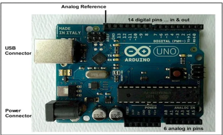
The Arduino Uno is a microcontroller board based on the ATmega328 (datasheet). It has 14 digital input/output pins (of which 6 can be used as PWM outputs), 6 analog inputs, a 16 MHz ceramic resonator, a USB connection, a power jack, an ICSP header, and a reset button. It contains everything needed to support the microcontroller; simply connect it to a computer with a USB cable or power it with a AC-to-DC adapter or battery to get started. The Uno differs from all preceding boards in that it does not use the FTDI USB-to-serial driver chip. Instead, it features the Atmega16U2 (Atmega8U2 up to version R2) programmed as a USB-to-serial converter.
"Uno" means one in Italian and is named to mark the upcoming release of Arduino 1.0. The Uno and version 1.0 will be the reference versions of Arduino, moving forward. The Uno is the latest in a series of USB Arduino boards, and the reference model for the Arduino platform; for a comparison with previous versions, see the index of Arduino boards.
coding a program using Arduino software in which Arduino controller takes input from the user and generates firing pulses for the TRIAC which controls the speed of the Induction motor. They had executed with the help of an Arduino controller kit.
In Arduino, the list of port that can be use in order to build controller, are as below [22]:
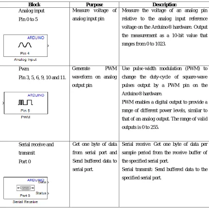
Table 2.1: The summary of the Arduino Uno.
Block Purpose Description
Analog input
Pin 0 to 5
Measure voltage of
analog input pin
Measure the voltage of an analog pin
relative to the analog input reference
voltage on the Arduino® hardware. Output
the measurement as a 10-bit value that
ranges from 0 to 1023.
Pwm
Pin 3, 5, 6, 9, 10 and 11.
Generate PWM
waveform on analog
output pin
Use pulse-width modulation (PWM) to
change the duty-cycle of square-wave
pulses output by a PWM pin on the
Arduino® hardware.
PWM enables a digital output to provide a
range of different power levels, similar to
that of an analog output. The range of valid
outputs is 0 to 255.
Serial receive and
transmit
Port 0
Get one byte of data
from serial port and
Send buffered data to
serial port.
Serial receive: Get one byte of data per
sample period from the receive buffer of
the specified serial port.
Serial transmit: Send buffered data to the
Table 2.2: The specification of Arduino Uno
Microcontroller ATmega328 Operating Voltage 5V
Input Voltage
(recommended) 7-12V Input Voltage (limits) 6-20V
Digital I/O Pins 14 (of which 6 provide PWM output) Analog Input Pins 6
DC Current per I/O Pin 40 mA DC Current for 3.3V Pin 50 mA
Flash Memory 32 KB (ATmega328) of which 0.5 KB used by bootloader
SRAM 2 KB (ATmega328)
EEPROM 1 KB (ATmega32
[image:38.612.151.508.442.658.2]The advantages of the Arduino are stated below:
(i) Inexpensive – Arduino embedded devices are inexpensive compared to other microcontroller embedded devices.
(ii) Cross-platform – Most microcontroller systems are limited to Windows. Different with Arduino, it can runs on Windows, Macintosh OSX, and Linux operating systems.
(iii) Simple, clear programming environment – The Arduino programming environment is easy to use for beginners.
REFERENCES:
[1] Marian P. Kazmierkowski and Lui Malesani,“ Current control techniques for three-phase voltage-source PWM converter: a survey”, IEEE Transanctions on industrial electronics,1998,Vol.45, No.5,pp.691-703.
[2] Dinu A., Burton D. ,Holme M.G., Roadley-Battin J. and Hubbard R. “Space vector-based hysteresis current controller with self monitoring mechanism”, IEEE International Symposium on Industrial Electronics, 2008, pp. 25-30, [3] Lekshmi A., Dr. Sankaran R. and Dr. Ushakumari, “Comparision of
performance of a closed loop PMSM drive system with modified predictive current and hysteresis controllers”, Proceedings of the 11th International Conference on Electrical Machines and Systems, ICEMS 2008, Wuhan, China,pp. 2876-2881.
[4] T.A. Lipo, “Recent progress in the development of solid state of Ac motor drives”, IEEE Trans, Power Electronics, Vol. 3, No. 2, April 1988, pp. 105-117. [5] Madhavi L. Mhaisgawali, Mrs S.P.Muley “Speed Control of Induction Motor
using PI and PID controller” IOSR Journal of Engineering (IOSRJEN), vol. 3, Issue 5 (May2013).
[6] Dr. P.S Bimbhra: “Power Electronics” – Khanna Publications, 2nd edition, 1998. [4] S. J. Chapman, “Electric Machinery and Power System Fundamental”, McGraw
Hill, 1st ed, 2002
[5] Babbage, C.; Herschel, J. F. W. (Jan. 1825). "Account of the Repetition of M. Arago's Experiments on the Magnetism Manifested by Various Substances during the Act of Rotation". Philosophical Transactions of the Royal Society of London115 (0): 467–496. doi:10.1098/rstl.1825.0023. Retrieved 2 December 2012.
[6] Thompson, Silvanus Phillips (1895). Polyphase Electric Currents and
Alternate-Current Motors (1st ed.). London: E. & F.N. Spon. p. 261. Retrieved 2 December 2012.
[8] Bimal K Bose, “An Adaptive Hysteresis-Band Current Control Technique of a Voltage-Fed PWM Inverter for Machine Drive System”, IEEE Transactions On Industrial Electronics, Vol. 31, No. 5, October 1990
[9] Baily, Walter (June 28, 1879). "A Mode of producing Arago's Rotation". Philosophical magazine: A journal of theoretical, experimental and applied physics (Taylor & Francis).
[10] Badder. U and Depenbrock. M (1992); “Direct self control (DSC) of inverter-fed induction machines: A basic for speed control without speed measurement”, IEEE Transactions on Industrial Application, Vol. 28, No. 3, pp. 581-588, West Germany.
[11] Jingwei Xu; Xin Feng; Mirafzal, B.; Demerdash, Nabeel A., "Application of Optimal Fuzzy PID Controller Design: PI Control for Nonlinear Induction Motor," Intelligent Control and Automation, 2006. WCICA 2006. The Sixth World Congress on, vol.1, no., pp.3953, 3957, 0-0 0.
[12] MATLAB 6.5: Help Documentation – Release Notes 13. [13] I. Bodela & S.A Nasar: “Vector control of AC Drives”.
[14] Bor–Ren Lin and Richard G–Hoft: “ Power Electronics Inverter Control with Neural Network, in IEEE-APEC, San Diego, pp. 128-134,1993.
[15] Srinivasa Rao Jalluri and B .B Sanker Ram, “Performance of Induction Motor Using Hysteresis Band PWM Controller”, Int. Journal Of Adv. In Eng. & Tech., May 2013.
[16] www.waset.org/journals/waset/v60/v60-252.pdf
[17] Jaime Fonseca, Joāo L. Alfonso, Júlio S. Martins ,Carlos Couto “Fuzzy Logic Speed Control Of An Induction Motor” Department of Industrial Electronics, Minho University Largo do Paco, Portugal .
[18] Jaydeep Chakravorty, Ruchika Sharma “ Fuzzy Logic Based Method of Speed Control of DC Motor” International Journal of Emerging Technology and Advanced Engineering, ISSN 2250 -2459, ISO 9001:2008 Certified Journal, Volume 3, Issue 4, April 2013.
[19] B Ventaka Ranganandh, A. Mallikarjuna Prasad, Madichetty Sreedhar, “
[20] Hamdy Mohamed Soliman and SM El Hakim, “Improved Hysteresis Current Controller to Drive Permanent Synchronous Motors through The Field Oriented Control,” International Journal of Soft Computing and Engineering, Vol 2, No.4, September 2012, pp.40-46.
[21] Hossein Madadi Kojabadi, ”A comparative analysis of different pulse width modulation methods for low cost induction motor drives, Energy Conversion and Management 52 (2011) 136–146
[22] Y. V. N. Kumar, P. H. Bindu, A. D. Sneha and A. Sravani, “A novel implemetation of phase control technique for speed control of induction motor using Arduino,” IJETAE,Vol. 3, Issue 4, Apr 2013, 469-472.