Building-integrated Carbon Capture: Development of
an Appropriate and Applicable Building-integrated
System for Carbon Capture and Shade
Harvey Bryan, Fahad Ben Salamah
*Herberger Institute for Design and the Arts, Arizona State University, United States
Copyright©2018 by authors, all rights reserved. Authors agree that this article remains permanently open access under the terms of the Creative Commons Attribution License 4.0 International License
Abstract
Building-integrated carbon capturing (BICC) represents a new approach to existing carbon capture technology called Moisture Swing Air Capture Technology, by attempting to integrate this carbon-capturing technology onto building facades. This approach treats building facades as giant artificial leaves that absorb carbon dioxide from the air and convert it into useful carbon-based materials without negatively impacting the environment. In this paper, we will explore how this technology can be modified to be installed on a building’s façade in the form of fabric shading devices that absorb carbon dioxide. A cleaning chamber moves along tracks (similar to a window-cleaning system) to moisten the fabric shades and dissolve the bicarbonate on the fibers. This process results in a carbonate and CO2 liquid can be compressed andstored for use in a variety of industrial applications. We will use performance data from several non-building devices that have been previously developed and tested to generate the magnitude of the CO2 that can be captured
with this type of technology.
Keywords
Building, Integration, CO2, Carbon,Capture
1. Introduction
Achieving stabilization of atmospheric CO2
concentrations at reasonable levels is looking less and less possible, especially given the present U.S. administration’s withdrawal from the Paris Climate Agreement [1] as well as their termination of the previous administration’s Clean Power Plan CO2 [2]. To keep
global average warming by century’s end to below a 2oC increase (preferable below 1.5oC increase) that is stipulated by the Paris Climate Agreement [3] will take considerable effort. To reach this global target a host of
aggressive and innovative strategies will need to be marshalled to meet this challenge. To date, most strategies have focused on CO2 mitigation at national levels; while
critically important, we also need to engage broader constituencies in combating global warming. Just as distributed renewable strategies have made a significant impact in achieving high levels of renewable penetration in many countries, the authors of this paper believe that a distributed approach can be applied to achieve rapid CO2
reduction. If this is at all possible, then the question becomes how do we move from a carbon-mitigating approach to one that also includes distributed carbon capturing?
One approach that currently stands out is the process by which nature captures CO2 from the atmosphere. In
essence, we plan to propose a form of biomimicry. Plants have been capturing CO2 for millennia, turning it into
carbohydrates and oxygen in a process known as photosynthesis. What if we treated building façades like giant artificial leaves—that is to say, building facades that could absorb CO2 from the air and convert it into useful
carbon-based materials without negatively impacting the environment?
In this paper, we will showcase carbon capture technologies from ambient air and we will explore in detail how such technologies can be modified to be installed on a building façade in the form of fabric shading devices that could provide dual functions; shading, and carbon capturing and regeneration.
2. Capturing Carbon Dioxide from
Ambient Air
Removing CO2 from air is not a new thing; it has been
around for decades in a process known as CO2 scrubbing,
which is used to generate CO2-free air [4]. CO2 scrubbing
and power plants, where carbon dioxide is removed before the exhaust released to the air. Yet, CO2 scrubbing is not
the same as air capture, because air capture doesn’t require removing all the CO2 from the air. Instead, air
capture aims to extract CO2 from the air efficiently [5].
Both technologies use a sorbent material to extract CO2,
with the difference being that air scrubbing requires less sorbent concentration due to the high concentration of CO2 in the air.
To date, we have reviewed several potential carbon capture technologies and selected the most promising ones for evaluation. The following sub-sections will showcase the technologies selected and will elaborate the evaluation process on which we think is the most suitable for our use.
2.1. Climeworks
The first carbon capture technology was developed by a company called Climeworks, which is based in Zurich; its product is considered the world’s first commercial carbon-removal technology. Each CO2 plant is equipped
with a fan that draws air into the device. The air passes through a filter, where the CO2 is chemically absorbed by
the filter’s sorbent material. Once a filter is saturated with CO2, heat is applied to it, thus facilitating the carbon
release. The CO2 is then collected and concentrated in
tanks so that it can be supplied to customers.
Although Climeworks was designed to capture CO2, it
won’t serve our goal of providing a building-integrated, aesthetically pleasing carbon-capture mechanism. Climeworks would block solar access, eliminate visibility, and negatively impact a building’s design. In addition to these architectural concerns, Climeworks also requires fans to increase the flow of air through the capturing filter, resulting in the use of significant fan energy.
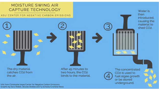
2.2. Moisture Swing Air Capture Technology
Another technology that looks promising is Moisture Swing Air Capture Technology, which Dr. Klaus Lackner developed at Arizona State University’s Center for Negative Carbon Emissions.
Dr. Lackner defines air capture technology in his 2009 article “Capture of Carbon Dioxide from Ambient Air” [6] as follows:
[image:2.595.134.460.391.530.2]“A passive, sorbent-based air collector can be viewed as a large filter standing in an airflow with the filter surfaces covered with or made from a CO2 selective sorbent. Air that comes in contact with sorbent surfaces will relinquish some or all of its CO2. The larger the surface area and the longer the contact time, the more CO2 is removed from the air.” Pg. 96
Figure 1. Climeworks: the CO2 capture and release process (source: Climeworks)
Figure 2. Moisture Swing Air Capture Technology: the CO2 capture and release process (source: Sara Weber, Brooke Stobbe and Ty
[image:2.595.136.461.549.732.2]Moisture Swing Air Capture Technology uses filter-like panels made of sorbent material; these panels are capable of capturing CO2 in a dry state and releasing it when
moisture is applied. Unlike Climeworks, the Moisture Swing Air Capture Technology depends on the natural flow of air and can thus capture CO2 at wind speeds as
low as 1 meter per second. These properties will allow us to avoid using elements such as blower fans and will also give us the opportunity to alter the technology to fit our needs regarding aesthetically pleasing integration with buildings.
2.2.1. Sorbent Material
In the process of selecting the right sorbent material, Dr. Lackner and his team tried a number of sorbents with the goal being to select a sorbent with lower binding energy (to allow for CO2 extraction) while maintaining a good
CO2 uptake rate. The evaluation process of different
sorbents led to the selection of a strong-base ion-exchange resin that has several appealing properties and suits the air-capture process. One of these properties is the release of CO2 by exposing it to water. The resin particles are
embedded in thin sheets of polypropylene, accounting for almost 60% of the total weight of the material. The sorbent selected was considered a successful choice because they combined two very important properties: low binding energy in the transition from carbonate to bicarbonate, and faster reaction kinetics [6].
2.2.2. Capture and Regeneration Cycle
The successful selection of the sorbent leads to the possibility of creating a cycle where CO2 can be loaded
into the resin and then extracted from it through the application of moisture. Once the resin is dry, it will again capture CO2. To put this cycle into practice, the thin
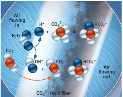
polypropylene sheets with the embodied resin is folded in the planes of the air filter to maximize the amount of sorbent material. They are then exposed to airflow to start the capturing process. The capture happens when air passes through the air filter fibres, where it is covered with negatively charged carbonate ions (CO32–) that
attracts the hydrogen ions (H+) from water molecules (H2O), forming bicarbonate (HCO3-). The remaining
hydroxide ions (OH-) capture the CO2 molecules in order
[image:3.595.314.530.78.248.2]form bicarbonate [7].
Figure 3. Chemical capture process (Source: Kevin Hand, Courtesy of
Columbia University, 2010)
Once the sheets are loaded with CO2, the resin is then
exposed to water inside a sealed enclosure to dissolve the bicarbonate on the fibers, which reverts to carbonate and CO2. The moisture drives the CO2 out of the resin,
creating a gas that can be compressed and stored as a liquid. Once the resin is dry, the cycle will continue by absorbing more CO2 [7].
The successful selection of sorbent and the laboratory experiments of the CO2 capturing cycle lead to the design
of the carbon carousel machine proposed by Dr. Lackner, which will be described in detail in the following section of the paper.
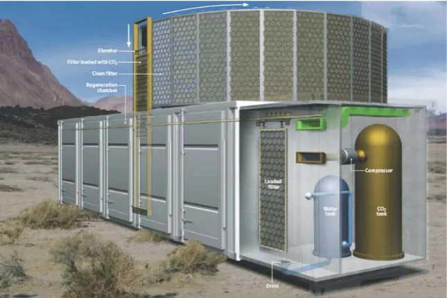
3. Carbon Carousel: One Big Filter
The goal of Dr. Lackner’s team is to design a device that can be built on the basis of current state-of-the-art technology and packaged in a single cargo shipping container for ease of transportation. The ability to transport such a device will not limit the device for a particular site. As CO2 is evenly distributed in the
atmosphere, the ability to transport such device will allow CO2 capturing wherever it has been generated around the
world. This device would be capable of capturing one ton of CO2 per day, by collecting one ton per day, the device
Figure 4. Carbon Carousel (Source: Kevin Hand, Courtesy of Columbia University, 2010).
Figure 5. Cleaning Process (Source: Kevin Hand, Courtesy of Columbia University, 2010).
The envisioned apparatus will mimic the laboratory experiment of carbon capturing from airflow but on a larger scale. The apparatus will involve a set of air filters that are 1m wide, 2.5m tall, from 0.3m to 0.4m thick. Each air filter has a total surface area that is equal to 2.5m2. The design was intended for an air speed of 1m/sec across the filter, which is suitable for locations with air speed of several meters per second. A number of various geometries were explored for the design of the air filter to maximize the flow of air and to allow for resin embodiment within the sheets. The selected design was a honeycomb-like structure with narrow but straight passages that function in a way similar to air filters that collect particles from airflow in a duct. Based on the filter design properties and concentration of the resin material, the continuous deployment of thirty air filters would capture one ton per day. However, due to the time required for recovery (the drying of filters takes a noticeably long time), the apparatus was designed to contain 60 filters to ensure a high rate of collection [6].
Carbon dioxide air filters are placed on an automated
conveyor, where the filters will be exposed to natural airflow. It is estimated that it will take one hour for the filter to become loaded with CO2. Once the filter is
saturated with CO2, an elevator-like moving mechanism
removes the air filter and places it in the evacuation chamber where the process of extracting CO2 takes place.
There are six chambers within the shipping container, and each holds 5 filter units. Once the chamber is filled with filter units, the air is evacuated. The filters are exposed to moisture, either by exposing them to briny water or by spraying clean water into the chamber to dissolve the bicarbonate on the fibers, which produces carbonate and CO2. The CO2 will be evacuated and
compressed into a storage chamber, and the water drained and collected for further CO2 extraction [7].
[image:4.595.137.461.317.472.2]energy in the system, as it involves the compression of CO2 from 5kPa to 6.7MPa in its liquid form. The last
energy-consuming step involves the compression and condensation of water vapor [6].
It is estimated that the total energy required to operate such a system is equivalent to 1.1 Mj/kg of CO2 [6].
Compared with the amount of CO2 generated as a result of
such an energy requirement, even in carbon-intensive economies, the CO2 captured using this system is almost 4
times the amount CO2 released as a result of the process
of energy generated for its use [6].
The following sections of the paper will discuss the potential adaptation and alteration of this carbon-capturing technology to being able to capture and regeneration of CO2 within cities and urban settlements in addition to the
use of building envelope as a collection canvas and will later describe in detail the envisioned Building-Integrated Carbon Capturing (BICC) mechanism.
4. Urban VS. Rural Carbon Capture
Urban areas can be defined as spatial concentrations of people in nonagricultural areas that have urban characteristics such as buildings, paved streets, cars, electric lighting, and sewage services; on the other hand, rural areas lack the previously mentioned urban characteristics [8]. The carbon carousel device was designed with the intension to capture CO2 in rural areas,
what if we could alter and modify such device to capture CO2 in urban settlements?
In the United States, commercial and residential buildings account for almost 39% of CO2 emissions [9],
and on-road vehicles account for 28% of the total fossil-fuel CO2 emissions [10]. Most of buildings’ CO2
emissions come from the use of fossil-fuel energy to provide cooling, heating, and lighting, as well as to power appliances and equipment within the buildings. Although the energy used in buildings may be generated in power plants in remote rural areas, the buildings are located in urban areas. The CO2 emissions that result from powering
buildings come from concentrated sources such as power plants can be captured on-site through carbon scrubbing. Furthermore, designing smart and highly efficient buildings may yield substantial reductions in energy use and CO2 emissions in cities. The U.S. Green Building
Council has suggested that an average LEED-certified building uses almost 32% electricity than an ordinary building, which can save up to 350 metric tons of CO2
emissions yearly [9].
On the other hand, reducing CO2 emissions from
vehicles through improved efficiency will lower CO2
emissions in urban areas but not eliminate them. Additionally, it is not feasible to provide onboard CO2
capturing for distributed sources such as vehicles at an
affordable cost [11]. That being said, what can buildings offer regarding carbon mitigation and sequestration?
Buildings account for a large proportion of the mass in urban areas, and this mass can be defined by surface areas such as roofs and facades. Although the emissions sources for providing energy to buildings are located in remote areas, this mass of surface areas represented in buildings need to be utilized somehow. For years, these surface areas were reserved for cladding and mechanical purposes, but the solar energy industry has stepped in to redefine those surfaces and use them to generate energy. The integration of these products into buildings is called building-integrated photovoltaics. What if carbon capture followed a similar approach, existing surface areas could be used to absorb CO2 from the air or for other
carbon-based applications?
5. Building Envelope as Carbon
Capture
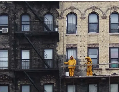
[image:5.595.308.535.435.611.2]When walking around urban centers, many people notice how dark the building facades are. Some may think that these buildings were built with dark materials as cladding, but others may wonder if the color has changed due to weathering. While researching this topic, we found images that show contrasts in the color of buildings’ exteriors before and after a cleaning process was conducted (see Figure 5).
Figure 6. Color contrast of building surfaces. The anonymous author
titled this post, “I used to think old buildings were made of dark bricks” (source: The Meta Picture).
rubber, asphalt, iron and other metals, fly-ash, quartz, calcite, and gypsum and other minerals, as well as organic substances and salt crystals. The authors concluded that the combustion of fossil fuels was responsible for a majority of such deposits in densely populated and polluted cities; in addition, the atmospheric transport of pollutants through winds was a major cause of deposits on buildings in areas where there was no local pollution source [12]. Thus, if buildings have a tendency, through weathering, to absorb pollutants such as carbon from fossil-fuel combustion, what is preventing people from actively capturing and utilizing CO2 in cities? The
technologies are available. Our aim in creating a building-integrated carbon capturing (BICC) device is to modify existing technologies so that they can be integrated within buildings’ envelopes to capture carbon and to help cities utilize it. This will help by lowering emissions, thus offsetting emissions from mobile sources such as automobiles.
6. Building-Integrated Carbon
Capturing
The potential carbon-capturing technology described earlier in this paper will be modified to be installed on building surfaces in the form of shading devices. This method will allow buildings to lower solar heat gain through shading while simultaneously capturing CO2
through the air filters attached to the building facade. Unlike the carbon carousel machine, building-integrated carbon capturing (BICC) will allow for carbon capturing in cities and urban settlements where the collected CO2 can be
stored for local use or shipped elsewhere for other applications.
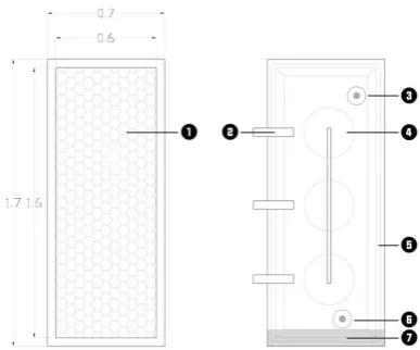
[image:6.595.322.516.78.239.2]BICC will mimic the properties of the air filters used in the carbon carousel machine. Thin fibers of sorbent material are arranged in a honeycomb-like arrangement that is similar to air duct filters. The alterations to the filter height, depth, and thickness are necessary to adapt the filter size to be implemented on building façades. The air filters in this system are 0.6m in depth, 1.6m in height, and 0.1m in thickness and it is similar to the air filters in the carbon carousel machine with respect to the sorbent material used. The filter devices will be attached to building façades vertically, forming a column of air filters that runs from the top of the building to the bottom, arranged in a way that fits between the window bays.
Figure 7. Front elevations of air filter (left) and cleaning chamber
(right). 1) Polypropylene sheets. 2) Connection to tracks. 3) Hose to CO2 tank. 4) Water Sprayers. 5) Sealant. 6) Hose to water tank. 7) Drain
The panels will be exposed to the air in a fixed and static condition. Unlike in the carbon carousel, the BICC panels will not move through a moving conveyor into the cleaning chamber. Once the air filters are loaded with CO2, a
moveable cleaning chamber has been designed as a replacement for the large stationary cleaning chamber in the carbon carousel machine. The moveable chamber moves along tracks (similar to a window-cleaning system) to moisten the fabric shades and dissolve the bicarbonate on the fibers. This produces carbonate and CO2 liquid. This
liquid undergoes processing to separate the water from the CO2, with the water being recycled back into the cleaning
apparatus and the CO2 being compressed and stored for use
in a variety of industrial applications. The cleaning chamber moves to the next panel while solar radiation dries the fabric shade panels, making them ready for the next cycle.
[image:6.595.321.522.495.665.2]The automated cleaning chamber will be connected through sealed hoses to two storage tanks—one for water used to extract the CO2, and the other for storing the
collected CO2.
Figure 9. Representation of cleaning chambers with hoses connected to
roof tanks.
To determine the number of moveable automated cleaning chambers a building requires, the design team must first calculate the number of air filters that will be integrated with the façades. The team must also take into consideration that the carbon-washing process takes almost one hour for an air filter with that type to be loaded with CO2 in addition to an equal amount of time for recovery
[image:7.595.59.289.134.249.2]and drying of the resin.
Figure 10. Cleaning chambers and tracks along building façade
The amount of CO2 collected by such system will
depend on the design, the available façade area, the height of the building, and the climate conditions at that particular site. To get a rough estimate of what one floor of a building could collect, we must set certain design parameters that could control the integration of the system on buildings. The thin side (0.1m) of air filters must be placed perpendicular to the façade. The filters need to be spaced at least one meter away from one another to allow for at least two automated cleaning chambers to move along.
To calculate roughly how much CO2 a building fitted
with BICC would collect, one must know the design properties for the particular building. For example, a building that is 25m in width, 36m in depth, and has a floor height of 3.2m; will allow for 22 rows of air filters per floor on the smaller sides of the building and 33 rows per floor
on the larger sides of the building. Since the building has 4 surfaces, and the height of the air filter is 1.6m, the total amount of air filters per floor for this building is 220. We are mimicking the carbon carousel filter properties in terms of sorbent concentration and the type of resin material used, in addition to basing the carbon capturing capacity of BICC on Dr. Lackner’s data regarding how much CO2 each filter
in the carbon carousel machine would collect and taking into consideration the time required for recovery and partial drying [11], each floor equipped with BICC is expected to collect roughly one ton of CO2 per day.
7. Carbon Utilization instead of Storage
Carbon capture and storage is one of the key options for lowering CO2 emissions to reduce global warming [13].
The captured CO2 can then be used in a number of
industrial applications, including metal and plastic manufacturing, oil and gas recovery, or it can be stored through the use of technologies such as geological or ocean storage in underground formations. However, in this case, in which we intend to capture CO2 within urban areas,
transporting the captured carbon to remote locations such as the ones mentioned above is a challenge, as it requires substantial investment in infrastructure. First, the captured CO2 must be compressed to pipeline grade, which requires
a significant amount of energy and cost. Second, a network of pipelines must be inserted within cities’ infrastructure so that the CO2 can be captured and stored locally. Third, a
local storage facility can be constructed within each urban area as a transit point before the carbon can be piped to the storage location. Finally, transporting the CO2 to the
remote storage facility must be done through pipelines or tankers. Pipelines are expensive investment, costing at least $50,000 for every mile on flat and dry terrain and reaching up to $700,000 per mile for offshore piping [14]. These four changes to the urban infrastructure will require significant costs, except for cities that were built with CO2
capture and storage in mind. Unlike in photovoltaics, for which the excess energy generated by a building’s solar power systems can, through the city’s existing infrastructure (i.e., the electrical grid), be transmitted to and used in remote locations, CO2 utilization within the
building or city may be the only reasonable and feasible option for the time being. The utilization of CO2 within
buildings or cities (e.g., for greenhouses, refrigeration, beverage carbonation, laundry, or the production of dry ice) will be discussed in the following section.
8. Carbon Utilization
The collected CO2 has a variety of local uses in local
[image:7.595.61.290.390.534.2]used as a cleaning product for dry cleaners, where it can be used as a liquid solvent for cleaning clothes. Another local use would be as a growth stimulator for indoor crops in its gas form. Collected CO2 can be stored and shipped to
remote sites and used in enhanced oil and gas recovery, where the injected CO2 facilitates the production of these
fuels. Some scientists consider this method to be one of the most successful strategies for storing and/or sequestration of carbon.
In addition to the above-mentioned utilization activities, another interesting approach is to turn CO2 into fuel using
sunlight. According to a new study developed by the U.S. Department of Energy’s Argonne National Laboratory and the University of Illinois at Chicago, the process developed is similar to the one found in trees and other plants, which capture CO2 from the atmosphere and convert it into sugar
[image:8.595.60.288.338.457.2]that stores energy using sunlight [15]. This technology can work hand in hand with the building integrated carbon capturing technology described here can be implemented within buildings, as it can occupy the roofs of buildings for solar exposure to facilitate the process.
Figure 11. Roof solar installation for carbon dioxide utilization
Larry Curtiss, the author of the study performed by the Argonne National Laboratory, has stated that the process of turning carbon dioxide into useable fuel requires finding a catalyst to make CO2 react more readily. Trees and plants
use an organic catalyst called enzymes to turn CO2 into
sugar fuels, whereas the researchers used a metal compound called tungsten diselenide. While enzymes turn CO2 into sugar fuels, the selected metal catalyst transforms
CO2 into carbon monoxide (CO), which is more reactive
than carbon dioxide. Scientists already have ways to convert CO into useable fuels such as methanol [16]. Peter Zapol, another author of the study [16], has also supported the mentioned transformation by stating:
“Making fuel from carbon monoxide means travelling ‘downhill’ energetically, while trying to create it directly from carbon dioxide means needing to go ‘uphill…’”
The transformation process uses the same ingredients of the photosynthesis, sunlight, water, and carbon dioxide, but results in a different product. The authors of the study describe the setup as an ‘artificial leaf’ and illustrate the process by dividing it into three major steps: the first is the
conversion of the photons of light into pairs of negatively charged electrons and positively charged holes. In the second step, the holes react with water molecules to create protons and oxygen. In the final step, protons, electrons, and carbon dioxide react to create CO and water [16].
The carbon dioxide used in the final step of this process will be supplied by the building integrated carbon capturing technology illustrated here. The transformation mechanism developed by the Argonne National Laboratory will utilize unused building roofs to take advantage of the solar exposure and to provide further utilization for the CO2 captured.
9. Proposed Trajectory
The ultimate goal of this research is to build a prototype with which to perform experimental evaluation studies and investigate BICC’s ability to achieve the original goals: self-shading and carbon capture and regeneration. We intend to produce inexpensive, scaled-down versions of the envisioned devices to investigate the solutions for the problems generated in the previous stage. This will form the experimental phase of the project; the solutions will be investigated and either accepted, improved, reexamined, or rejected based on the data generated. Further alterations and refinements may occur to rule out as many malfunctions as possible for the sake producing the best possible device. At the end of this experimental phase, we will have a better understanding of the device’s constraints and of the problems that we will need to further investigate, and we will have a better perspective on how the device would behave in real-life scenarios.
10. Discussion and Conclusion
We conclude that BICC is physically possible, and it will add a collection system within cities that surpasses the uptake rate of natural CO2 sinks such as trees by several
orders of magnitude. To have a significant impact on carbon emissions in the atmosphere, the uptake rate of a single building must be evaluated by orders of magnitude. A 20-story building similar to the example mentioned earlier would collect almost 20 tons of CO2 per day. Ten
buildings of that size within a city could collect 200 tons of CO2 per day. That may sound like a very small number in
comparison with global CO2 emissions. The world emits
nearly 29 Gt of CO2 yearly [6]. But almost 750,000
commercial buildings were constructed in the United States between the years 2003 and 2012 [17]. If 50% of these buildings implemented the BICC strategy, this will lead to a collection rate of 2.73 Gt/yr, which could have a significant impact on the world’s CO2 emissions.
The system properties and the amount of CO2 collected
location. If a building has 4 sides, the wind speed along the windward side differs from the wind speed on the leeward side. The difference in airflow may lead to changes in air filter thickness and the amount of sorbent required for collection. A location with fast-blowing air would require a collector with a small frontal area and greater filter depth, whereas another location with slow-blowing air would require a larger frontal area and a thinner filter [6]. This problem can be solved by designing two separate air filter units—one tailored for windward surfaces, and one tailored for leeward surfaces.
The present air-capture device is climate sensitive, meaning that tropical climates with high humidity as well as extremely cold climates may limit the operation of the device. In hot and humid climates, the humidity limits the absorption rate and load capacity of the resin, whereas in cold climates, the collection of CO2 works, but the drying
rate of the filters is much slower than in warmer climates [6]. The sorbent material used for the air filters was designed specifically to work for desert climates where the absorption rate of the resin and the drying time of the filters gives the devices a high collection rate. For such a system to operate successfully in other climates, the air filters must be altered accordingly.
Another benefit of BICC would be that it could offsets past emissions and offers a great solution for offsetting emissions that are hard to avoid, such as emissions from airplanes and automobiles [6]. Once successfully developed and implemented, and in collaboration with other existing technologies such as the carbon carousel, BICC will provide a valuable option, whether through keeping up with the world’s emissions or through reducing the CO2 content in the atmosphere.
Acknowledgements
We would like to thank Dr. Klaus Lackner and his colleagues at Arizona State University’s Center for Negative Carbon Emissions for all their help in developing this paper.
REFERENCES
[1] New York Times. Our Disgraceful Exit from the Paris Pact. June 2, p.A24, 2017.
[2] Davenport, C. & A. Rubin. Trump Signs Executive Order Unwinding Obama Climate Policies. New York Times. March 28, p.A1, 2017.
[3] FCCC. Adoption of the Paris Agreement. Framework Convention on Climate Change (FCCC), United Nations, Paris, 2015.
[4] Astarita, G. Mass Transfer with Chemical Reactions. Elsevier Publishing Company, 1967.
[5] Lackner, K.S., H.J. Ziock, & P. Grimes. Carbon Dioxide Extraction from Air: Is it an Option? In Proceedings of the 24th International Conference on Coal Utilization & Fuel Systems, Clearwater, Florida, 1999.
[6] Lackner, K.S. Capture of carbon dioxide from ambient air. In The European Physical Journal Special Topics, 176(1), p.93-106, 2009.
[7] Lackner, K.S. Washing carbon out of the air. In Scientific American, 302(6), p.66-71, 2010.
[8] Weeks, J. R. Defining urban areas. In Remote sensing of Urban and Suburban areas (pp. 33-45). Springer Netherlands, 2010.
[9] Council, U. G. B. Green Building and Climate Resilience. Ann Arbor, 1001, 48109, 2011.
[10]Gately, C. K., Hutyra, L. R., & Wing, I. S. Cities, traffic, and CO2: A multidecadal assessment of trends, drivers, and
scaling relationships. Proceedings of the National Academy of Sciences, 112(16), 4999-5004, 2015.
[11]Lackner, K. S., Grimes, P., & Ziock, H. J. Capturing carbon dioxide from air, 2001.
[12]Nord, A. G., Svärdh, A., & Tronner, K. Air pollution levels reflected in deposits on building stone. Atmospheric Environment, 28(16), 2615-2622, 1994.
[13]Shahbazi, A., & Nasab, B. R. Carbon capture and storage (CCS) and its impacts on climate change and global warming. J Pet Environ Biotechnol, 7(291), 2, 2016.
[14]IEAGHG, IEA Publication. CO2 Pipeline Infrastructure.
IEAGHG Report 2013/18.
[15]Sagoff, J. A New Leaf: Scientists Turn Carbon Dioxide Back Into Fuel. Online available from https://energy.gov/articles/new-leaf-scientists-turn-carbon-d ioxide-back-fuel
[16]Asadi, M., Kim, K., Liu, C., Addepalli, A. V., Abbasi, P., Yasaei, P., & Zapol, P. Nanostructured transition metal dichalcogenide electrocatalysts, 2016.