REFINEMENT OF OUTER ROTOR PERMANENT
MAGNET FLUX SWITCHING MACHINE FOR
DOWNHOLE APPLICATION
RAJESH KUMAR
REFINEMENT OF OUTER ROTOR PERMANENT MAGNET FLUX SWITCHING MACHICE FOR DOWNHOLE APPLICATION
RAJESH KUMAR
A thesis submitted in
fulfillment of the requirement for the award of the Master in Electrical Engineering
Faculty of Electrical and Electronic Engineering Universiti Tun Hussein Onn Malaysia
iii
This dissertation is dedicated to my parents, my brother and sister, who always encouraged me with their love and prayers.
ACKNOWLEDGEMENT
I am very thankful to God, for His grace and His blessings given to me for the successful completion of my master’s studies.
I would like to express my sincere gratitude to my supervisor, Assoc. Prof. Ir. Dr. Erwan Sulaiman, for providing the opportunity to be one of his students. His guidance, precious help, continuous encouragement, constructive and critical comments encouraged me during entire work of my research.
I acknowledge, with bundle of thanks to ORICC, Universiti Tun Hussein Onn Malaysia and Ministry of Higher Education (MOHE), Malaysia for their financial assistance throughout the master project.
Without support from technical staff and my laboratory colleagues of FSM research group, this research would not have been initiated. My sincere thanks go to my co-supervisor Dr. Md Zarafi Ahmad for his technical explanations and important contributions. I am also grateful to Mr. Mahyuzie Jenal for sharing his theoretical knowledge with continuous support.
Besides, it has been an extremely wonderful and charming experience to carry out research work in UTHM with a gathering of exceptionally devoted persons, who have dependably been willing to give assistance, bolster, and empower me whenever needed.
v
ABSTRACT
ABSTRAK
vii
TABLE OF CONTENTS
DECLARATION ii
DEDICATION iii
ACKNOWLEDGEMENT iv
ABSTRACT v
ABSTRAK vi
TABLE OF CONTENTS viii
LIST OF TABLES xi
LIST OF FIGURES xii
LIST OF SYMBOLS AND ABBREVIATIONS xiv
LIST OF PUBLICATIONS xvii
CHAPTER 1 INTRODUCTION 1
1.1 Research Background 1
1.2 Electrical Machine in Downhole Application 3
1.3 Problem Statement 5
1.4 Objectives of the Study 6
1.5 Scope of the Research 7
1.6 Contribution to Knowledge 7
1.6 Dissertation Organization 8
CHAPTER 2 REVIEW OF ELECTRIC MACHINE FOR THE
ix
2.1.1 Induction Machine (IM) 10
2.1.2 Switched Reluctance Machine (SRM) 13 2.1.3 Permanent Magnet Machine (PMM) 16 2.1.4 Flux Switchinng Machine (FSM) 17
2.1.5 Various Topologies of PMFSM 19
2.1.6 Modeling Techniques of of PMFSM 23
2.2 Optimization Approaches for PMFSM 24
2.2.1 Deterministic Optimization Method (DOM) 25
2.2.2 Stochastic Method 27
2.3 Performance Comparison of Electric Dowhole Machine 28 2.4 Summary 31
CHAPTER 3 RESEARCH METHODOLOGY 32
3.1 Machine Modeling Procedure 33 3.1.1 Analytical Sizing Equation 33
3.1.2 Modeling Procedure Using JMAG 36
3.1.3 Armature Coil Arrangement 38
3.2 Optimization Approach 40 3.3 Performance Examination of PMFSM for Downhole Application 41
3.3.1 Torque Density and Power Density 43
3.3.2 Rotor Mechanical Properties 44
3.3.3 PM Demagnetization at High Temperature 44
3.4 Summary 45
CHAPTER 4 PERFORMANCE ANALYSIS OF OUTER ROTOR PMFSM FOR DOWNHOLE APPLICATION 46
4.1 Initial Results Based on Various Rotor Pole Number 46
4.1.6 Torque-Power versus Speed Characteristics 57
4.1.7 Summarized Comparison of Various Rotor Number 59
4.2 Optimization Method Based on DOM 59
4.2.1 Split Ratio 60
4.2.2 Rotor Pole Width and Height 61
4.2.3 PM Width and Radial Length 62 4.2.4 Number of Turns 63 4.3 Performance Analysis 64 4.3.1 Magnetic Flux Characteristic 65 4.3.2 Path Flow of PM Flux 65 4.3.3 No-current/Cogging Torque Analysis 66 4.3.4 Induced Voltages 67 4.3.5 Torque versus Ja 67 4.3.6 Torque and Power versus Speed Characteristics 69 4.3.7 Motor Losses and Efficiency 70 4.3.8 Torque and Power Density 71 4.3.9 Stress Analysis of Optimized Topology 71 4.3.10 PM Demagnetization at High Temperature 72 4.3.11 Overall Performance Comparison of Initial and Optimized Topology 73
4.5 Summary 74 CHAPTER 5 CONCLUSION 75
5.1 Conclusion 75
xi
LIST OF TABLES
1.1 Component failure in ESP system 4
2.1 Standard electric machine from Borrets Group 12
2.2 Machine specifications for SRM 15
2.3 12/14 PMFSM design specifications 22
2.4 Performance comparison: induction vs. PM 29
2.5 General efficiency comparison for electric machines 29
2.6 General comparison between three downhole machines 30
2.7 Performance comparison of different PM machines 31
3.1 Modeling parameters of outer rotor PMFSM 35
3.2 Control and full mode conversion setting 38
4.1 Phase representation of armature coil 50
4.2 Performance comparison of various rotor poles 59
4.3 Initial and optimized modeling parmaeters 64 4.4 Detailed losses and efficienceis for initial and optimized
model 70
LIST OF FIGURES
1.1 Global energy consumption 1
2.1 Multi rotor induction motor 12
2.2 Failure distributon of offshore induction machine 13 2.3 Simple 2/2 switched reluctance motor 14
2.4 4 phsase 8slot-6pole SRM for ESP 15
2.5 PMDC brushless machine for downhole application 16 2.6 Interior PMSM for downhole application 17
2.7 A single phase switching alternator 18
2.8 Categorization of FSM 19
2.9 Working principle of PMFSM 20
2.10 Topologies of PMFSM 21
2.11 12slot-14pole inner rotor PMFSM for downhole application 22 2.12 Simulated output torque waveform of 12slot-14ple 23 2.13 Work flow diagram of deterministic method 26
2.14 Genetic algorithm flow chart 28
3.1 Project implementation flow chart 32
3.2 Key modeling parameter of outer rotor PMFSM 33 3.3 Work flow to model and investigate outer rotor PMFSM 37 3.4 Flow chart for armature coil arrangement analysis 39
3.5 Circuit diagram for armature coil 39
3.6 Parameters for optimization 40
3.7 Deterministic optimization procedure 41 3.8 Performance examination based on FEA 42 3.9 Estimated coil end volume of the outer rotor PMFSM 43 3.10 Flow chart for demagnetization analysis 45
4.1 Outer rotor PMFSM 47
xiii
4.3 Flux pattern of coil 1 to coil 4 48
4.4 Flux pattern for coil 5 to coil 12 49
4.5 Three phase flux linkage of outer rotor PMFSM 50 4.6 Armature coil arrangement of outer rotor PMFSM 50 4.7 Complete structures of 12slot outer rotor PMFSM with 51 4.8 Three phase flux linkage of 12slot with 10, 14 and 22pole 53 4.9 U-phase flux linkage of 12slot outer rotor PMFSM 53 4.10 Cogging torque analysis of outer rotor PMFSM with 12slot 54 4.11 Flux lines and distribution of 12slot with 10, 14 and 22pole 56 4.12 Induced voltages at 1000 r/min for various topologies 56 4.13 Torque vs. Jafor outer rotor PMFSM 57
4.14 Speed characteristics 58
4.15 Parameters for optimization of 12slot-2p2pole 60 4.16 12slot-22pole split ratio analysis for five cycles 60 4.17 Average output torque at various rotor pole width 61
4.18 Rotor pole variation vs. torque 61
4.19 Influence of PM width on average torque 62 4.20 Torque at PM radial length deviation 62 4.21 Output torque with respect to number of turns 63 4.22 Optimizaed schematic of 12slot-22pole outer rotor PMFSM 64 4.23 U-phase flux linkage of initial and optimized topology 65 4.24 Flux lines and distribution of 12slot-22pole 66 4.25 Cogging torque analysis for one electric cycle 66 4.26 Induced voltages comparsion at 1000 r/min 67 4.27 Simulated and calculated torque comparison 68 4.28 output torque of original and optimized topology 68
4.29 Torque-power versus speed analysis 69
LIST OF SYMBOLS AND ABBREVIATIONS
r
N
- Number of rotor poless
N
- Number of stator slotsr - Rotor pole width arc
s - Stator tooth width arc
pm - Permanent magnet width arc
slot - Armature slot width arc
Rsi - Stator inner radius
Rso - Stator outer radius
Rro - Rotor outer radius
hys - Stator back length
hyr - Rotor yoke length
hpr - Rotor pole height
Aslot - Half stator slot area
Nc - Coil number of each phase
m
- Phase numberNa - Number of turns
Im - Peak injected current
Ja - Armature current density
- Filling factorfe - Electrical frequency
fm - Mechanical frequency
- Flux Linkage
r
xv
- Efficiencycog
- Electrical angle of rotation for each period of coggingtorque
- Stack lengthkl - Leakage factor
c
P
- Copper lossi
P
- Iron loss
- Copper resistivityk
- Natural numberβg - Maximum air gap flux density at open circuit
Sa - Slot area
Lend - End coil length
Rout - Outer radius of end coil
Rin - Inner radius of end coil Ne - Electrical angle of revolution
V1 - Volume of coil slot
V2 - Volume of coil end
T
- TorqueBLDC - Brushless Direct Current
CAD - Computer Aided Design
DC - Direct Current
DFT - Discrete Fourier Transform
DOM - Deterministic Optimization Method
EMF - Electromotive Force
ESP - Electrical Submersible Pump
FEA - Finite Element Analysis
FEFSM - Field Excitation Flux Switching Machine
FSM - Flux Switching Machine
GA - Genetic Algorithm
H - Height
HCF - Highest Common Factor
HTHP - High Temperature High Pressure
IFP - Institute of Petroleum
IM - Induction Machine
IPSM - Interior Permanent Magnet Machine
L - Length
LCM - Least Common Multiple
MEC - Magnetic Equivalent Circuit
NEMA - National Electrical Manufacturing Association
PCP - Progress Cavity Pump
PM - Permanent Magnet
PMDC - Permanent Magnet Direct Current
PMFSM - Permanent Magnet Flux Switching Machines
SRM - Switch Reluctance Machine
VFD - Variable Frequency Drive
xvii
LIST OF PUBLICATIONS
Journals:
(i) Rajesh Kumar, Erwan Sulaiman, Mahyuzie Jenal and Fatihah Shafiqah Bahrim, “Parametric Optimization and Performance Analysis of Outer Rotor Permanent Magnet Flux Switching Machine for Downhole Application,”
Journal of Magnetics, vol.22, no.1, pp. 69-77, Mar. 2017. (ISI, Scopus, IF: 0.421)
(ii) Rajesh Kumar, Erwan Sulaiman, Mahyuzie Jenal, Lailai Iwani Jusoh and Fatihah Shafiqah Bahrim “Design and Investigation of Outer Rotor Permanent Magnet Flux Switching Machine for Downhole Application,”
International Journal of Power Electronics and Drive Systems, vol.8, no.1, pp. 231-238, Mar. 2017. (Scopus, Q3)
(iii) Rajesh Kumar, Erwan Sulaiman, Laili Iwani Jusoh and Fatihah Shafiqah
Bahrim, “Design of Outer Rotor Permanent Magnet Flux Switching Machine for Downhole Application,” International Journal of Applied Engineering Research, vol. 12, no. 7, pp. 1383-1388, Apr. 2017. (Scopus, Q4)
Proceedings:
(iv) Rajesh Kumar, Erwan Sulaiman, Faisal Khan, Laili Iwani Jusoh and Fatihah Shafiqah Bahrim “Influence of Rotor Pole Number on the Performance of Outer Rotor Permanent Magnet Flux Switching for Downhole Application,”
(v) Rajesh Kumar, Erwan Sulaiman, Mahyuzie Jenal, Aqeel Ahmed Bhutto and Danish Ali Memon, “Design Refinement and Performance Analysis of Outer Rotor Permanent Magnet Flux Switching Machine for Downhole Application,” 4th International Conference on Energy Environment and Sustainable Development, Jamshoro, Pakistan, 01-03 Nov. 2016. (accepted and presented)
(vi) Rajesh Kumar, Erwan Sulaiman, Hassan Ali Hyder Abbas Musavi, Ganesh
Kumar and Izhar Ahmed , “Electromagnetic Analysis of Outer Rotor Permanent Magnet Flux Switching Machine for Downhole Application,”
IEEE 2017 International Conference on Innovation in Electrical Engineering and Computational Technologies, Karachi, Pakistan, pp. 1-6, 05-07 Apr. 2017.
(vii) Rajesh Kumar, Erwan Sulaiman, Hassan Ali, Laili Iwani Jusoh, Fatihah Shafiqah Bahrim and Md. Fairoz Omar, “Design Enhancement and Performance Examination of External Rotor Switched Flux Permanent Magnet Machine for Downhole Application,” International Conference on Electronics and System Engineering & Technology, Melaka, Malaysia, 6th May. 2017. (accepted and presented)
(viii) Rajesh Kumar, Erwan Sulaiman, Md Zarafi Ahmad, Syed Muhammad Syed
CHAPTER 1
INTRODUCTION
1.1 Research Background
[image:19.595.162.505.510.675.2]Energy is the main impetus of the world. It is a fundamental element of development and advancement. The anticipated energy prerequisite from various assets to guarantee the advancement of the worldwide economy from now to 2035 appeared in Figure 1.1 [1]. As depicted from the graph, oil and gas still remain the most imperative source in the coming decades since the advancement of renewable assets is not advancing as quickly as expected. The majority of the increased production of oil and gas in forthcoming years is from the following two main sources: mature fields and deep water reservoirs [2].
Figure 1.1: Global energy consumption [1]
operation and support are not set up. On the other hand, a review made by French Institute of Petroleum (IFP) inferred that 40% of the offshore oil and gas would originate from water profundities up to 500 m, 20% in the vicinity of 500 m and 1500 m and 40% from 1500 m to 3000 m. Until 2000, a negligible 2% of imminent assets had been explored in deep and ultra-deep waters [3]. The worldwide oil and gas chase for new oil and gas assets is driving us into ever more profound waters and harsher climate. The best technique to endeavor more oil and gas resources in the deep water and create them in an ensured, capable and more ecological way is a challenge. In the present time, traditionally fixed or drifting platform for processing are extensively utilized but they are costly to build and install. Furthermore, the dismounting of settled platform additionally costs in millions afterward. With the customary advancement in technology, numerous deep and ultra-deep water reservoirs may in this manner be useless to develop [4].
Downhole processing, by moving the processing from topside or inland to downhole cannot just take out the top stages or somewhat diminish the top territory but also generally improve production, extreme recuperation and preparing productivity while diminishing ecological effects. With the increase of the seawater depth, the downhole temperature and pressure increase. The risks and demanding performance requirements for High Temperature and High Pressure (HTHP) completions dictate special considerations and investments. The electrification of the downhole application has turned out to be promising for enhancing the oil recuperation all the more securely, monetarily and ecologically amicable, especially for deepwater seaward wells. However, there are still a few difficulties connected with the innovation due to the cruel HPHT condition such as power transmission, power electronics and electric machine [5].
3
180°C with an exponential breakdown rate over 135°C. As of now, downhole machine are typically determined from either inland or from topside. Recently developed high-temperature semiconductor devices can withstand high temperature up to 210°C, which makes it conceivable to drive the motor downhole [7].
To legitimize secure, cost-effective and eco-accommodating practical answer for upgrading oil and gas efficiency from deep and ultra-deep water repository, new downhole technologies are prescribed. Since electric machine assumes the driving part in the downhole application, it is a crushing prerequisite for scientists to outline and create an advance electric machine that bears the qualities of high reliability, better efficiency, high torque density and easy control [8]. The current approved electric downhole machine is the induction machine which is slightly incompetent. Besides, the natural shortcoming of low beginning torque and high beginning current restraints induction machine to low torque, high-speed applications. In applications where high torque is mandatory, a mechanical gear is typically added to coordinate the torque, this not just further decline the framework effectiveness but also debases the framework dependability. On the contrary, Permanent Magnet (PM) machines having higher efficiencies, higher torque densities and smaller volumes, are generally utilized in modern applications to supplant traditional machines. However, few have been created for the downhole applications because of the high encompassing temperatures in deep wells and the low-temperature dependability of PM materials after some time. Today, with the improvement of cutting edge innovations and utilization of high-temperature magnets, it is progressively intriguing for oil and gas businesses to create PM machines for the downhole applications [9].
1.2 Electric Machine in Downhole Application
The prerequisites of a downhole machine are fundamentally reliant on particular applications. In general, an electric downhole machine should have the following basic characteristics of superior reliability & robustness, high torque & efficiency, and simple control.
Pump (ESP). This estimation incorporates the cost of a drilling rig needed to install and evacuate an ESP, labour cost, seaward transportation, and so on, barring the cost of the ESP itself and the loss of production between the periods. The component failure in ESP systems listed in Table 1.1. As it can be seen that the greater part of the failures happen from the electric motors [10-11].
Table 1.1:Component failure in ESP system [10]
Components % Failure
Assembly 1
Cable 21
Sensor 1
Pump 30
Gas Handler 1
Motor 32
Intake 4
Protector 10
Other 1
Keeping in mind the end goal to dispose of the gear system prescribed for high torque applications, and henceforth enhancing the reliability and proficiency of the entire system, the downhole machine ought to give high torque over a wide range. Whereas, high efficiency is constantly favourable for applications, particularly in downhole where it is hard to have an outer cooling system for dispersing heat in light of the restricted cross-sectional area. Whereas, high efficiency implies fewer losses and subsequently less heat produced [12-13]. Furthermore, it is challengeable to have estimation devices working precisely in the downhole environment. Sensor-less control is attractive for downhole applications in view of the accompanying focal points [14-15].
(i) Decrement in hardware complication and expenditure (ii) Increased mechanical strength and general potency (iii) Operation in unfriendly condition
5
1.3 Problem Statement
The current standard electric machine for downhole application is induction machine which is marginally ineffective. In addition, it has a peculiar inadequacy of low starting torque and high starting current restricts induction machine to low-torque, high speed applications. In high torque operations, a mechanical gear is routinely combined to facilitate the torque, this not simply further lessening the structure proficiency, similarly, degrades the system unfaltering quality. Apart from this, PM machines having greater efficiencies, greater torque densities and more diminutive volumes, are universally employed in present day applications to supersede the conventional machines. However, few have been created for the downhole applications in view of the high climatic temperatures in underwater reservoirs and the low-temperature strength of PM materials over the time. Today, with the change of forefront developments and usage of high-temperature magnets, it is logically entrancing for oil and gas organizations to modeled and develop PM machines for the downhole applications [16-17].
A Permanent Magnet Direct Current (PMDC) downhole machine has been proposed for the downhole application. The direct current is easily transmitted through PMDC to downhole by diminishing the transmission losses. It is smooth to control since it doesn't need Variable Frequency Drive (VFD). Although, it has few flaws, for instance, the commutator framework in PMDC not just produces the complication in assembling, additional losses over the brushes and furthermore causes persistent failure. Besides, consistent substitution is required after 2-3 years. With a specific end goal to resolve the issue of brushes, a brushless Interior Permanent Magnet Synchronous Machine (IPMSM) has been modeled and developed but it requires extra cooling arrangement [18-19].
advantages, such as robust rotor structure, high torque and flux densities, high productivity and better flux weakening ability are comprehensively dissected and monitored for various applications. More recently, an inner rotor PMFSM was modeled and developed for the downhole application which has high average output torque and efficiency when compared with previously modeled machines but it has high copper losses mainly due the high number of turns. Furthermore, high utilization of PM weight makes machine heavier and expensive [20-22].
Setting the rotor on the outer surface may deliver more torque, appeared differently in relation to the routine inside rotor [23]. In any case, examination on the PMFSM has generally fixed on the electromagnetic examination and enhancement of the internal rotor machines with hardly gave cautious attention to the outer rotor PMFSM for the downhole application [24-25]. Therefore, an improved structure of outer rotor PMFSM with salient rotor is proposed for the downhole application to overcome all these problems.
1.4 Objectives of the Study
The primary target of this research is to model and improve outer rotor Permanent Magnet Flux Switching Machine (PMFSM) for downhole application. In accomplishing the primary goal, there are some specific objectives that have to be fulfilled, which are:
(i) To investigate the initial performances of outer rotor PMFSM for downhole application based on various rotor pole topologies.
(ii) To optimize finest topology based on rotor pole combination using deterministic for obtaining optimum torque and power.
7
1.5 Scope of the Research
The proposed configuration of outer rotor PMFSM for the downhole application is modeled through analytical approach where outer diameter, machine stack length and air gap fixed at 100 mm, 200 mm and 0.5 mm respectively. In addition, the limit of maximum current density is set at 5 Arms/mm2 for armature windings due to high ambient temperature [3]. Based on literature, 12slot-10, 14 and 22 pole topologies are initially modeled and investigated for downhole application [3,125]. The three phase model with various rotor pole numbers were inspected and compared initially through commercial Finite Element Analysis (FEA), JMAG-Designer ver.14.1, issued by Japan Research Institute (JRI) was utilized as 2D-FEA solver. The initial performance of the finest topology is optimized by deterministic method based on several parameter located on stator and rotor [25]. The electromagnetic performance, containing back EMF, cogging torque, flux pattern and average output torque were inspected and compared for initial and optimized model. The torque-power versus speed attributes were assessed by varying the armature phase angle, θ. The iron and copper losses were computed in light of 2D-FEA and formulas, which help in figuring the efficiency of proposed outer rotor PMFSM for the downhole application. Furthermore, the demagnetization is carried under maximum temperature of 180oC [124].
1.6 Contribution to Knowledge
Furthermore, it have 0% reverse PM magnetization where the surrounding temperature of downhole application is 140oC without external cooling
1.7 Dissertation Organization
This thesis deals with modeling, optimization and performance investigation of outer rotor PMFSM for the downhole application. The thesis is divided into five chapters and the brief outline of each chapter is listed as follows:
(i) Chapter 1: Introduction
The first chapter set the brief background of downhole application and explains the importance of PM machine in this application. The issues associated with past machines are spotlighted and research targets to resolve the issues along with the real commitments are sketched out in this chapter. (ii) Chapter 2: Review of Electric Machines for Downhole Application
The following chapter reviews the state-of-art about electric the downhole machine. The characteristics comparisons considering several parameters of these machines are thoroughly discussed. The wordy explanation is provided for structure review, performance analysis, analytical modeling and optimization of PMFSM. In the last section, the performance is compared to several machines for finding the best candidate for the downhole application. (iii) Chapter 3: Research Methodology
This chapter three portrays the methodology of proposed external rotor PMFSM utilizing business 2D-FEA, JMAG-Designer ver. 14.1, issued by JSOL Corporation. Sizing equations, drawing procedure and armature coil arrangement analysis are highlighted. In a later segment, the technique of deterministic optimization and is disclosed to treat different parameters of the machine and upgrade its qualities. Finally, the path flow for the performance has been explored in detail.
(iv) Chapter 4: Performance Analysis of Outer Rotor PMFSM for Downhole Application
9
PMFSM for the downhole application. Further, evaluation of finest slot-pole combination is executed under open and close circuit analysis based on 2D-FEA. Then the finest topology 12slot-22pole is optimized utilizing deterministic technique until the objective torque is accomplished. The outcomes of the preliminary and optimized model which met the target performances are analyzed and discussed. Finally, torque and power density, the mechanical strength of machine and reverse magnetization is calculated for optimized model.
(v) Chapter 5: Conclusion
CHAPTER 2
REVIEW OF ELECTRIC MACHINES FOR DOWNHOLE APPLICATION
This chapter reviews the types of rotating electric machine for downhole application. Different types of electric machines are clarified, from the early ideas to the cutting edge outline. Merits and demerits of various machines are highlighted and various methodologies are discussed to assess their performances. As the thesis is on outer rotor PMFSM, more detail and significance of these machines is provided in the last section.
2.1 Classification of Electric Downhole Machine
Concerning the interest for high reliability, efficiency and torque density, there are primarily three sorts of electric machines considered for the downhole applications:
2.1.1 Induction Machine (IM)
11
in the stator, the rotor will never accomplish its rotating magnetic field speed i.e. the synchronous speed. There are essentially two sorts of induction machine that based on the input supply i.e. single phase and three phase induction machine respectively. Single phase induction machine is not a self-starting machine while three phase induction machine is a self-starting machine. Besides, three phase induction machine is grouped into two kinds i.e. Wire wound induction machine and squirrel cage induction machine [26].
Since the inception of Electric Submersible Pumps (ESP) in the downhole application, polyphase squirrel cage rotor water-proof sealed induction motors have traditionally been used for ESPs where surrounding temperatures can frequently achieve 240oF. Squirrel cage induction motors are used in ESPs because of its ruggedness, reliability, simplicity, relatively good efficiency, low cost and wide scale availability. An IM motor, due to limitation dictated by bore diameter, has a high stack length to diameter ratio. Therefore, designing and developing a small-diameter IM to meet the horsepower requirements in the downhole application required major deviations from normal National Electrical Manufacturing Association (NEMA) motor designs. To comfortably fit inside common oil-well casings, the industry has mostly settled on outside diameters of 3.75, 4.56 or 5.62 inches for the motors. Figure 2.1 shows the geometrical schematic of a regular multi-rotor induction motor with an external diameter across is regularly between 3.9 mm to 11.8 mm and the length is typically from 5 to 10 m, even up to the length of 30 m or longer reliant on applications. The stator is twisted as a solitary unit and the rotor comprises of various electrically discrete rotors with bearings between them to suit the slender structure. The oil, having low compressibility, makes it perfect with the high surrounding pressure existing because of submergence. The most well-known power range is from 40 to 200 kW. More power can be accomplished with the incorporation of extra motors [27-29].
should either be fed through an inverter or redesigned with optimization algorithms. The optimization of induction motor design has been carried through several methods such as conventional optimization technique, AI based optimization technique and nature-inspired algorithm but none is able to resolve all problems [31-33].
Figure 2.1: Multi rotor induction motor (a) Internal view (b) External view [29]
Table 2.1: Standard induction machine from Borets Group [30]
Specifications Borets EDB8-103B5 Borets EDB8-117B5 Borets EDB22-130B5
Outer Diameter [mm] 103 117 130
Power Rating [kW] 10.7 10.7 29.5
Rated Voltages [V] 300 380 660
Efficiency [%] 79 82 81
Power Factor 0.8 0.83 0.87
Motor Weight [kg] 100 103 172
Length [mm] 1740 1615 1828
Rated Current [A] 24.5 18.0 27.5
Besides, a survey was conducted that covers 2600 induction machines utilized in Norwegian offshore industry. The failure distribution is depicted in Figure 2.2. The most frequent failure in IM is caused by bearing fault. The prolonged passage of relatively small electric current, usually due to current leakage, e.g. from shorted lamination, or eddy currents which create fluting and that leads to typical bearing failure. Flutes are deep, exhibit noise, vibration, and fatigue. The second
13
[image:31.595.187.452.332.520.2]most frequent failure of IM is produced by the stator winding insulation breakdown. There are three kinds of the stator winding insulation: phase-to-phase (primary insulation system), turn-to-turn (secondary insulation system) and phase-to-ground insulation (ground wall). The main failure root causes of the stator winding insulation deterioration: surges, mechanical stress, contamination, electrical and thermal stress. The third main reason of induction motor failure is broken, cracked or corroded rotor bars which are mainly caused by frequent duty cycle and pulsating mechanical load. These problems require high maintenance facility. Moreover, the induction machines inborn drawback of low starting output torque, high beginning current, and limits induction machine to low torque in speedy applications. For high torque, a mechanical gear is included to coordinate the torque and this will decrease machine efficiency [34-36].
Figure 2.2: Failure distribution of offshore induction machines[34]
2.1.2 Switched Reluctance Machine (SRM)
electronic devices, accurately timed switching is not a problem, and the SRM is a famous design for modern stepper motors [37-38].
The fundamental operating principle of the SRM is very straightforward; as current is passed through one of the stator windings. The torque is produced by the propensity of the rotor to adjust with excited stator pole as shown in Figure 2.3. The path of torque created is an element of the rotor position with respect to the energized phase, and is independent of the current flow direction through the phase winding.
Continuous torque can be produced by intelligently synchronizing each phase’s
[image:32.595.198.441.287.496.2]excitation with the rotor position. By shifting the number of phases, stator poles, and of rotor poles, a wide range of SRM geometries can be figured it out [39-40].
Figure 2.3: Simple 2/2 switched reluctance motor [39]
15
Table 2.2: Machine specifications for SRM
Design Parameters Values
Number of Rotor Poles 6
Number of Stator Slot 8
Stator Outer Diameter [mm] 139 Stator Inner Diameter [mm] 70 Rotor Outer Diameter [mm] 69 Rotor Inner Diameter [mm] 42.04
Air Gap [mm] 0.5
Stack Length [mm] 70
Motor Speed [r/min] 3000
Output Power [kW] 2.23
Peak Current [A] 15
[image:33.595.181.457.365.599.2]Their fundamental downside and exclusion criterion until now has been the high torque ripple at low speeds and a significant acoustic noise due to high air-gap induction [43]. Additionally, the control of the SRM is more complicated than that of a three-phase drive, due to the high non-linearity of the determination of the current switching angle. Therefore, few SRM has been designed and developed for the functional downhole application [3].
Figure 2.4: 4 phase 8slot-6pole SRM for ESP [42]
2.1.3 Permanent Magnet Machines (PMM)
Permanent magnet (PM) machines, having higher efficiencies, higher torque densities, and smaller volumes, have broadly been utilized in numerous industrial applications to supplant regular machines, yet few have been developed for the downhole applications due to the low temperature solidness of PM materials in past time. Today, with the improvement of cutting edge technologies and applications of high-temperature magnets, it is progressively fascinating for oil and gas businesses to fabricate PM machines for downhole applications where the machine outer diameters are typically limited to 100–200 mm by well sizes, but the axial lengths can be relatively long [44].
[image:34.595.195.444.572.740.2]Previously, a Permanent Magnet Direct Current (PMDC) downhole motor with brushes was designed for the downhole application. Its speed is controlled by just changing the DC current from topside, and no Variable Speed Drive (VSD) is required. The fundamental impediment of this motor is that the brushes re-present additional maintenance that is amazingly expensive for seaward applications [3]. In this manner, this kind of motor is for the most part restricted to inland applications. To resolve the issue of brushes, a PM Brushless Direct Current (BLDC) was introduced, shown in Figure 2.5. It has capacity to produced high temperature and can withstand at high temperature around 230oC. Moreover, the outer diameter meter 80mm while axial length is relatively long, with operating torque of 420 Nm and peak power of 20 kW [5]. On the other hand, PM BLDC machine has physically larger size that requires complicated hardware and software for control system with high maintenance [45].
17
[image:35.595.212.429.257.402.2]An interior PM synchronous machine (IPMSM) has been developed for ESP pump used in downhole application, shown in Figure 2.6. It has outer diameter of 100 mm with 10 rotor pole and 18 stator slots. The IPMSM has high average efficiency of 95.9% with high reliability and simple control. However, it has high cogging torque, ripples torque and requires extra cooling facility to avoid demagnetization [46-47]. Therefore in brief, it can be concluded that the PM machine for the downhole applications holds gigantic guarantee of conveying high torque over entire operation ranges including startup, yet is still in its outset [48].
Figure 2.6:Interior PMSM for downhole application [46]
2.1.4 Flux Switching Machines (FSM)
investigation exercises, regularly Finite Element Analysis (FEA) utilizing 2D or 3D, contributed a considerable measure in design and examination, and optimisation of switched flux machines. In the course of recent years, numerous novel FSM topologies have been produced for variety of applications, going from economical household appliances, automobiles, wind power, and aviation [56-57].
[image:36.595.135.504.383.588.2]The basic mechanism of flux switching alternator depicted in Figure 2.7(a) and (b) with a couple of stator winding, a double arrangement of laminated yolks, and a pair of PMs were situated on the stator, while the rotor was appeared as a pair of salient pole with stacks laminations on the shaft. The path flow of flux is highlighted by arrows in Figure 2.7(a) demonstrate the stream of the flux flows from left to right in both windings. At the point when the rotor position was moved by a half-electric cycle, as in Figure 2.7(b), the flux linkage had a similar magnitude yet the direction had been turned around as in Figure 2.7(a). A total inversion of flux was accomplished by each revolution of the rotor. Therefore, the salient pole of the stationary part and stator worked in a customary pulsating flux manner.
Figure 2.7: A single phase switching alternator [50]
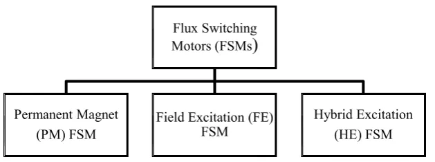
There are three classes of FSMs, to be specific permanent magnet FSM (PMFSM), field excitation FSM (FEFSM), and hybrid excitation FSM (HEFSM). They are comprehensively characterized and separated by field flux source i.e. PM or field winding and both PM and field windings, as represented in Figure 2.8 [58].
19
Figure 2.8: Categorization of FSM
2.1.5 Various Topology of PMFSM
Over the past decade, PMFSM has become fascinating research interest in various applications mainly due to number of perceived advantages. Since every single active part, for example, armature windings and PM situated on the stator, clear yet feasible machine cooling can be easily associated [59]. Also, additional preferences, such as rigid rotor structure, high torque and flux densities, high efficiency and better flux weakening ability are thoroughly explored and inspected for plentiful applications. Furthermore, the flux produced by PMFSM is fixed and will not change-diverged which means it is constant flux [60-62].
The universal operating principle of the PMFSM is outlined in Figure 2.9(a) and (b), where the dark arrow demonstrates the flux line of PM for instance. In Figure 2.9(a) when rotor pole adjusts to the one of the stator teeth over which a coil is wound, the flux from PM is connected in the coil transfer into the rotor pole. Whereas, in Figure 2.9(b) when rotor advances to adjust to the next stator teeth has a place with a similar coil, the infused flux is stepped back to the stator tooth by the rotor pole, keeping a similar value of flux-linkage while turning the polarity, i.e. accomplishing the flux-switching idea. Therefore, as the rotor turns in forward direction, the flux linkage in the coil will change methodically, actuating back EMF. is manner, if current is appropriately nourished into the coil, an electromagnetic torque will be built up, driving the rotor to move ahead [63-64].
The group of PMFSM have been ceaselessly growing since the primary PMFSM was proposed. Plentiful designs of PMFSMs have been proposed globally by specialists to achieve better attributes of torque, speed, power and efficiency. The advancement and distinct structures have been reviewed in [65]. For low energy axial
Flux Switching Motors (FSMs)
Permanent Magnet (PM) FSM
Field Excitation (FE) FSM
fan applications, a single phase PMFSM with the 4/4 stator and rotor poles configuration and modest ferrite magnets was suggested as a cheap solution [66]. while a 2/2 structure with outer diameter of 64mm was presented as potential contender for high speed applications [67]. In these single phase machine, profiled asymmetric air gaps are needed in order to obtain self starting ability.
Figure 2.9: Working principle of PMFSM (a) flux linkage correspond to one polarity (b) flux linkage switch polarity as the salient pole rotates
Meanwhile, three phase ferrite based PMFSM with 6/4 and 6/5 setups were designed for low-cost medium-speed applications [68] but the major challenges of a ferrite based machine concern the low remnant flux density and low coercive [68]. Furthermore, three phase Nd-Fe-B based conventional 12/10 PMFSM was developed, where each stator tooth is wounded by concentrated armature coil shown in Figure 2.10 (a) [54]. A PM was set between U-shaped laminated segments and the polarity of PM was turned around starting with one magnet then onto the next while a three-phase PMFSM, alternate poles wound windings were explored to be fault tolerant, as appeared in Figure 2.10(b) [69]. In any case, these PMFSMs had the weakness of high magnet volume. To lessen the volume of PM, another structure of E-center PMFSM was produced by supplanting the alternate wound pole with a straightforward stator tooth, as showed in Figure 2.10 (c) [70]. Besides, to upgrade the attributes of E-center PMFSM, the stator tooth was expelled to augment the slot area and thus C-core PMFSM was produced, as represented in Figure 2.10 (d) [71]. In addition, the multi-tooth structure of PMFSM was used to enhance the torque density and lessen magnet utilization, as in Figure 2.10 (e) [72]. A three-phase segmental rotor PMFSM was also explained, as appeared in Figure 2.10 (f).
Stator
Rotor
Coil
PM PM
21
(a) (b)
(c) (d)
[image:39.595.121.532.69.736.2]
(e) (f)
Figure 2.10: Topologies of PMFSM (a) 12S-10P PMFSM with all poles wound (b) PMFSM with alternate poles wound (c) E-core PMFSM (d) C-core PMFSM (e) Multi-tooth PMFSM (f) Segmental rotor PMFSM all poles wound
A1 A1 C1 A2 A2 A1 B1 B1 B1 C1 C1 B1 C1 B2 C2 B2 C2 A1 C1 A1 B1
B1 C1
C1
A1 B1
B1 C1
A2 C2 A2 B2 B2 C2 C1 A1 B1 B1 C1 A1 A1
C1 B1
A machine with the 12/14 with inner rotor configuration and the conventional laminated structure depicted in Figure 2.11, was proposed for downhole applications. It has PMs in the stator with a doubly salient stator and rotor like a reluctance machine with an outer diameter of 100 mm and an active stack length of 200 mm. The complete design specification of inner rotor PMFSM for downhole application is illustrated in Table 2.3. In terms of performance, it can provide average output torque up to 25 Nm depicted in Figure 2.12 with output power of 2.7 kW. Additionally, it has efficiency of 88% where ambient temperature is 150oC [73]. Apart from this, the high utilization of PM not only increase the weight but also uneconomical with high chances of PM reverse magnetization. Additionally, it utilizes high number of turns that causes high copper losses which degrades efficiency of inner rotor PMFSM.
Figure 2.11: 12slot-14pole inner rotor PMFSM for downhole applications [73]
Table 2.3: 12/14 PMFSM machine design specifications
Design Parameters Values Machine Outer Diameter [mm] 100
Stack Length [mm] 200
Synchronous Speed [r/min] 1000
Air Gap [mm] 0.5
Stator Slot 12
Rotor Pole 14
[image:40.595.188.453.595.766.2]23
Figure 2.12: Simulated output torque waveform of 12slot-14pole [3]
Keeping in mind the end goal to achieve higher torque density at low speed condition, an external rotor with 12slot and 22pole PMFSM has been proposed for urban electric vehicle propulsion. It has benefits of basically sinusoidal back-electromotive force (EMF) waveforms with high output torque of 25 Nm when phase current is set at 76 A [74]. Furthermore, the external rotor configuration also has lower total weight and cost. The former also has advantages such as ease of installation, maintenance and cooling [75]. Therefore, the outer rotor structure can be more suitable candidate in offshore applications when compared to inner rotor PMFSM [76].
2.1.6 Modeling Techniques for PMFSM
12/10 PMFSM in order to anticipate the electromagnetic performance, i.e., the air-gap field distribution, the phase flux linkage and back-EMF, the self- and mutual inductances, the d- and q-axis inductances, and the electromagnetic torque [20]. Moreover, different nonlinear MEC models are built up for the PMFSM with 12/10 and 12/14 [79-80] topologies. It would include a lot of work to develop such expound MEC models for the assigned PMFSM, and henceforth variable global reluctance networks which can gather, adjust, and illuminate MEC models of various parts of the PMFSM quickly are proposed to limit the endeavors included [81]. All in all, the analytical strategies from the literature are limited to the most widely recognized setups of the PMFSM.
These days, FEA has been routinely utilized to anticipate the performance of the electrical machines because of the advances in development instruments and computer innovation. For the PMFSM, FEA has practically turned into the standard numerical modeling tool and been utilized as a part of all the current writing about the PMFSM either to approve the analytical methods or to straightforwardly assess the machine performance. For the radial flux, 2-D FEA is the most well-known numerical technique as it can convey sensibly precise outcomes with generally short computational time [82], while the tedious 3-D FEA is completed to represent the discernible end impacts [83]. Most importantly, FEA has been the standard of modeling since the PMFSM initially presented decades prior.
2.2 Optimization Approaches for PMFSM
77
REFERENCES
[1] “World Energy Outlook 2013,” International Energy Agency, pp. 1-687. [2] “Oil and Gas Industries Technology Master Plan,” European Oil and Gas
Innovation Forum, pp. 1-34, Feb. 2004.
[3] A. Chen, “Investigation of permanent magnet machine for downhole application,” PhD thesis, Norwegian University of Science and Technology, Trondheim, Norway, January 2011.
[4] I. Sandrea and R. Sandrea, “Global oil reserves – recovery factors leave vast target for EOR technologies,” J. Oil & Gas, pp. 1-8, Nov. 2007.
[5] A. Chen, R. B. Ummaneni, R. Nilssen, and A. Nysveen, “Review of electrical machine in downhole application and the advantages,” Proceeding of 13th International Power Electronics and Motion Control Conference
(EPE-PEMC), pp. 799-803, Poznan, Poland, 1-3 Sep. 2008.
[6] H. Devold, “Oil and gas production handbook,” ABB Group, pp. 1-152, Aug. 2013.
[7] T. Proehl and F. Sabins, “Drilling and completion gaps for HPHT well in deep water,” Global Deepwater Technology Development, pp. 1-70, Jun. 2006.
[8] “Advanced ultra-high speed motor for drilling,” United States Department of
Energy, pp. 1-49, 1st Feb. 2007.
[9] S. F. Rabbi, M. A. Rahman and S. D. Butt, “Modeling and operation of an
interior permanent magnet motor drive of electrical submersible pumps,” in
Proceeding of Ocean-St. John, Canada, pp. 1-5, 14-19 Sept. 2014.
[10] M. W. Hooker , C. S. Hazelton, K. S. Kano and M. L. Tupper, “High
-temperature electrical insulations for EGS downhole equipment,” in
Proceeding of 35th Workshop on Geothermal Reservoir Engineering,
[11] N. Griffiths and S. Breit, “The world’s First wire line retrievable electric
submersible pumping system” in Proceeding of European Artificial Lift
Forum, Aberdeen, Scotland, 28th Feb. 2008.
[12] S. Zhang , L. Norum , R. Nilssen and R. D. Lorenz, “Down-the-hole hammer drilling system driven by a tubular reciprocating translational motion
permanent magnet synchronous motor,” in Proceeding of IEEE International
Symposium on Industrial Applications, Hangzhou, China, pp. 647-651, 28-31
May. 2012.
[13] H. Kuemmlee, P. Wearon and F. Kleiner, “ Large electrical drives – setting
trends for oil & gas applications,” in Proceeding of 55th IEEE Petroleum and
Chemical Industry Technical Conference, Cincinnati, USA, pp. 1-9, 22-24
Sept. 2008.
[14] M. Rahimi, M. Rausand and S. Wu “Reliability prediction of offshore oil and gas equipment for use in an arctic environment,” in Proceeding of International Conference on Quality, Reliability, Risk, Maintenance, and
Safety Engineering, Xi'an, China, pp. 1-6, 17-19 Jun. 2011.
[15] P. Vas, “Sensor less Vector and Direct Torque Control”. Oxford University Press. 1998.
[16] Offshore Design & Energy Equipment (2014). “A myriad of motor technology,” Retrieved on March 25, 2016, from http: //offshoreeuropejournal.com/news/archivestory.php/aid/7818/A_myriad_of_ motor_technology!html
[17] M. J. Melfi, S. Evon and R. Mcelveen, “Induction versus permanent magnet
motor,” IEEE Ind. Appl. Magz., vol. 15, no. 6, pp. 28-35, Oct. 2009.
[18] M. Solesa and V. Sagalovskiy, “Direct current motors with permanent
magnets-more downhole flexibility,” in Proceeding of Middle East Artificial
Lift Forum (MEALF), Sultanate of Oman, Feb. 2007.
[19] S. F. Rabbi, P. Brown, N. Drover, C. Kennedy and M. A. Rahman,
“Modeling and control of a hysteresis IPM motor drive for electric
submersible pumps,” in Proceeding of IEEE International Electric Machines
& Drives Conference (IEMDC), Coeur d'Alene, USA, pp. 742-748, 10-13
79
[20] Z. Q. Zhu, Y. Pang, D. Howe, S. Iwasaki, R. Deodhar and A. Pride, “Analysis of electromagnetic performance of flux switching PM machine by non-linear adaptive lumped parameter magnetic circuit model,” IEEE Trans. Magn., vol. 41, no. 11, pp. 4277-4287, Nov. 2005.
[21] Z. Q. Zhu, J. T. Chen and D. Howe, “Analysis of a novel multi tooth flux
switching PM brushless ac machine for high torque direct drive applications,”
IEEE Trans. Magn., vol. 44, no. 11, pp. 4313-4316, Nov. 2008.
[22] C. Pollock, H. Pollock, R. Barron, J. R. Coles, D. Moule, A. Court, and R.
Sutton, “Flux-switching motors for automotive applications,” IEEE
Trans. Ind. Appl., vol. 42, no. 5, pp. 1177–1184, 2006.
[23] C. V. Aravind, M. Norhisam, I. Aris, D. Ahmad and M. Nirei, “Double rotor
switched reluctance motors: fundamentals and magnetic circuit analysis,” in
Proceeding of IEEE Student Conference on Research and Development, Cyberjaya, Malaysia,pp. 294-299, Dec. 2011
[24] E. Sulaiman, T. Kosaka and N. Matsui “Design and analysis of high-power/high-torque density dual excitation switched-flux machine for traction drive in HEVs,” Renew. Sust. Energ. Rev., vol. 34, pp. 517–524, Jun. 2014. [25] M. Jenal, E. Sulaiman and R. Kumar, “A new switched flux machine
employing alternate circumferential and radial flux (AlCiRaF) permanent magnet for light weight EV,” J. Magn, vol. 21, no. 4, pp. 537-543, Dec. 2016 [26] S. J. Chapman, Electrical Machinery Fundamental. 3rd Edition. McGraw Hill
International. 1999.
[27] T. R. Brinner, R. H. McCoy and T. Kopecky, “ Induction versus permanent -magnet motors for electrical submersible pump field and laboratory
comparison,” IEEE Trans. Ind. Appl., vol. 50, no. 1, pp. 174-181, Jan-Feb. 2014.
[28] E. B. Agamloh and A. Cavagnino, “High efficiency design of induction machines for industrial applications,” in Proceeding of IEEE Workshop on
Electrical Machines Design Control and Diagnosis (WEMDCD), Paris,
France,pp. 33-46, Mar. 2011.
[29] J. R Smith, D. M. Grant, A. Al-Mashgari and R. D. Slater, “Operation of
systems,” in Proceeding of IEEE Electrical Power Applications, pp. 544-552, Nov. 2000.
[30] Borets. Oil Field Equipments. Retrieved on December 20, 2016, from http://www.borets.ru/upload/file/Boretc2.pdf
[31] B. Singh and B. N. Singh, “Experience in the design optimization of a voltage source inverter fed squirrel cage induction motor,” Elec. Pow. Sys. Res., vol. 26, pp. 155-161, 1993.
[32] E. S. Abdin, G. A. Ghoneem, H. M. M. Diab, and S. A. Deraz, “Efficiency
optimization of a vector controlled induction motor drive using an artificial
neural network,” in Proceeding of The 29th Annual Conference of IEEE
Industrial Electronics Society, Roanoke, USA, pp. 2543-2548, 2003.
[33] C. Cao, B. Zhou M. Li and J. Du, “Digital implementation of DTC based on PSO for induction Motors,” in Proceeding of the 6th World Congress on
Intelligent Control and Automation, Dalian, China, pp. 6349-6352, 2006.
[34] J. Cibulka, M. K. Ebbesen, G. Hovland, K. G. Robbersmyr and M. R. Hansen, “A review on approaches for condition based maintenance in applications with induction machines located offshore,” Mod. Cont. Iden., vol. 33, no. 2, pp. 69–86, 2012.
[35] R. Dabbousi, D. Savinovic and Y. Anundsson, “A comparison between induction & synchronous motors for applications in the oil & gas industry,”
in Proceeding of 55th IEEE Petroleum and Chemical Industry Technical
Conference, Cincinnati, USA, pp. 1-7, 31st Oct. 2008.
[36] Control Engineering Magazine. “Permanent Magnet Motors Outperform
Induction Motors in Many Applications,” Illinois. 24th Nov. 2012.
[37] J. Latimer. Digital Variable Reluctance Technology Could Result in Positive
Changes in the Efficiency and Power of Pumps. Retrieved on February 25,
2017, from http://www.pumpsandsystems.com/motors/making-smarter-motor [38] W. A. Aljaism, “Switched reluctance motor: design, simulation and control,”
PhD thesis, University of Western Sydney, Australia, 2007.
[39] T. L. Angle, J. G. Shaw, S. Cummins and M. Turner, “A new unique high
-pressure pump system,” in Proceeding of 22nd International Pump Users
81
[40] R. A. Gupta, R. Kumar and S. K. Bishnoi, “Modeling and control of nonlinear switched reluctance motor drive,” J. Elec. Eng., pp. 1-7. 2010. [41] S. Vetriselvan and S. Srinivasan, “Reduce torque ripple using novel torque
distribution function for high-speed applications using embedded system
technology,” Int. J. Adv. Res. Comp. Sci. Soft. Eng., vol. 4, no. 10, pp. 490-494, 2014.
[42] M. Sundaram, P. Navaneethan and T. D. Kumar, “Design and development
of energy efficient submersible switched reluctance motor,” J. Eng. Tech, vol.4, no.1, pp.70-77, Jan-Jun. 2014.
[43] H. K. Patel, R. Nagarsheth and S. Parnerkar, “Performance comparison of
permanent magnet synchronous motor and induction motor for cooling tower
application,” Int. J. Emg. Tech. Adv. Eng., vol.2, no. 8, pp. 167-171, 2012. [44] A. Chen, R. Nilssen, and A. Nysveen, “Performance comparisons among
radial-flux, multistage axial-flux, and three-phase transverse-flux PM
machines for downhole applications,” IEEE Trans. Ind. Appl., vol.46, no.2, pp.779-789, Mar-Apr. 2010.
[45] M. Shirania, A. Aghajania, S. Shabania and J. Jamalib, “A review on recent applications of brushless DC electric machines and their potential in energy saving,” Energy Equip. Sys., vol. 3, no. 1, pp. 57-71, Jan. 2015.
[46] Z. Binyi, L. Binxue, F. Guihong and Z. Fuyu, “Research of multipolar
permanent magnet synchronous submersible motor for screw pump,” in
Proceeding of IEEE International Conference on Mechatronics and
Automations, Harbin, China, pp. 1011-1016, 5-8 Aug. 2007.
[47] F. Parasiliti, M. Villani, S. Lucidi and F. Rinaldi, “Finite element based multi-objective design optimization procedure of interior permanent magnet synchronous motors for wide constant-power region operation,” IEEE. Tran.
Ind. Elec., vol. 59, no. 6, pp. 2503-2514. Jun. 2012.
[48] S. F. Rabbi and M. A. Rahman, “Equivalent circuit modeling of a hysteresis interior permanent magnet motor for electric submersible pumps,” IEEE.
Trans. Mag., vol. 52, no. 7, Jul. 2016.
[50] S. E. Rauch and L. J. Johnson, “Design Principles of Flux-Switch
Alternators,” AIEE Trans. Power. App. Syst, vol. 74, no. 3, pp. 1261–1268, Jan. 1955.
[51] A. E. Laws, “An electromechanical transducer with permanent magnet polarization,” Technical Note No.G.W.202, Royal Aircraft Establishment, Farnborough, UK, 1952.
[52] A. K. Dasgupta, “Analytical Method to find the Best Number of Stator and Rotor Teeth of Inductor Alternator for 3-Phase Sinusoidal Voltage
Generation,” AIEE Trans. Power App. Syst., vol. 79, no. 50, pp. 674–679, Oct. 1960.
[53] M. Subbiah, and M. R. Krishnamurthy, “Single-Winding Single-Phase Inductor Alternator,” IEEE Trans. Aerosp. Electron. Syst., vol. 12, no. 6, pp. 689–697, Nov. 1976.
[54] E. Hoang, A. H. Ben-Ahmed, and J. Lucidarme, “Switching flux permanent
magnet poly-phased synchronous machines,” in Proceeding of 7th European
Conference on Power Electronics and Applications (EPE), Trondheim,
Norway, vol. 3, pp. 903–908, Sep. 1997.
[55] C. Pollock, and M. Wallace, “The flux switching motor, a DC motor without
magnets or brushes,” in Proceeding of IEEE 34th Industry Applications
Society Annual Meeting (IAS), Pheonix, Arizona, USA, vol. 3, pp. 1980–
1987, Oct. 1999.
[56] Chuang Yu and S. Niu, “Development of a magnetless flux switching machine for rooftop wind power generation,” IEEE Trans. Ene. Conv., vol. 30, no. 4, Dec. 2015.
[57] J. F. Bangura, “Design of high-power density and relatively high-efficiency flux-switching motor,” IEEE Trans. Ene. Conv., vol. 21, no. 2, Jun. 2006. [58] L. I. Jusoh, E. Sulaiman and S. M. N. S. Othman, “Comparative study of
single phase FE, PM and HE flux switching motors,” in Proceeding of IEEE
Student Conference on Research and Development, Kuala Lumpur, Malaysia,
pp. 583-588, 13-14 Dec. 2015.
[59] Z. Q. Zhu, “Switched flux permanent magnet machines - innovation
continues,” in Proceeding of International Conference on Electrical
83
[60] E. Sulaiman, T. Kosaka and N. Matsui, “High power density design of 6 -slot-8-pole hybrid excitation flux switching machine for hybrid electric vehicles,”
IEEE Trans. Magn., vol. 47, no. 10, pp. 4453-4456, 2011.
[61] E. Sulaiman, T. Kosaka, and N. Matsui, “Design optimization and performance of a novel 6-slot 5-pole PMFSM with hybrid excitation for
hybrid electric vehicle,”IEEJ Trans. Ind. Appl., vol. 132, no. 2, pp. 211-218, 2012.
[62] E. Sulaiman, “Design studies on less rare-earth and high power density flux switching motors with hybrid excitation / wound field excitation for HEV drives,” PhD thesis, Nagoya Institute of Technology Nagoya, Japan, 2012. [63] Y. Wang, M. J. Jin, J. X. Shen W. Z. Fei and P. C. K. Luk, “An outer-rotor
flux-switching permanent magnet machine for traction applications,” IEEE
Energy Conversion Congress and Exposition, Atlanta, USA, pp. 1723 – 1730,
Sept. 2010.
[64] W. Hua, M. Cheng, Z. Q. Zhu and D. Howe, “Design of flux-switching permanent magnet machine considering the limitation of inverter and
flux-weakening capability,” in Proceeding of IEEE Industry Applications
Conference Forty-First IAS Annual Meeting, Tampa, USA, pp. 2403-2410,
Oct. 2006.
[65] Z. Q. Zhu and J. T. Chen, “Advanced flux-switching permanent magnet
brushless machines,” IEEE Trans. Magn., vol. 46, no. 6, pp. 1447-1453 Jun. 2010.
[66] Y. Cheng, C. Pollock, and H. Pollock, “A permanent magnet flux switching motor for low energy aixal fans,” in Proceeding of IEEE Industrial
Application Society Annual Meeting, Kowloon, China, vol. 3, pp. 2168-2175,
Oct. 2005.
[67] Y. Chen, S. Chen, Z. Q. Zhu, D. Howe, and Y. Y. Ye, “Starting torque of
single-phase flux-switching permanent magnet motors,” IEEE Trans. Magn., vol. 42, no. 10, pp. 3416-3418, Oct. 2006.
[68] W. Fei and J. X. Shen, “Comparative study and optimal design of PM switching flux motors,” in Proceeding of 41st International Universities
[69] A. S. Thomas, Z. Q. Zhu, R. L. Owen, G. W. Jewell, and D. Howe, “Fault tolerant flux switching PM brushless AC machines,” IEEE Trans. Ind. Appl., vol. 45, no. 6, pp. 1971–1981, 2009.
[70] J. T. Chen, Z. Q. Zhu, S. Iwasaki, and R. Deodhar, “A novel E-core flux switching PM brushless AC machine,” in Proceeding of IEEE Energy
Conversion Congress and Exposition, Atlanta, USA, pp. 3811–3818, Sept.
2010.
[71] X. Feng, L. Xianxing, D. Yi, S. Kai, and P. Xu, “A C-core linear flux
switching permanent magnet machine with positive additional teeth,” in
Proceeding of 17th International Conference on Electrical Machines and
Systems (ICEMS), Hangzhou, China, pp. 1757-1761, 22–25 Oct. 2014.
[72] Z. Q. Zhu, J. T. Chen, and D. Howe, “Analysis of a novel multi-tooth flux switching PM brushless ac machine for high torque direct-drive
applications,” IEEE Trans. Magn., vol. 44, no. 11, pp. 4313–4316, 2008. [73] A. Chen, R. Nilssen and A. Nysveen, “Investigation of a three-phase
flux-switching permanent magnet machine for downhole applications”, in
Proceeding ofInternational Conference on Electrical Machines and Systems,
Rome, Italy, pp. 1-5, Sep. 2010.
[74] W. Fei, P.C. Luk, J. Shen and Y. Wang, “A novel outer-rotor permanent-magnet flux-switching machine for urban electric vehicle propulsion,” in
Proceeding of IEEE International Conference on Power Electronics Systems
and Applications, Hong Kong, China, pp. 1-6, 2009.
[75] M. Z. Ahmad, E. Sulaiman, Z. A. Haron and T. Kosaka, “Preliminary studies
on a new outer-rotor permanent magnet flux switching machine with hybrid
excitation flux for direct drive EV applications,” in Proceeding of IEEE
International Conference on Power and Energy, Kota Kinabalu, Malaysia,
pp. 928-933, 2-5 Dec, 2012.
[76] R. Kumar, E. Sulaiman, M. Jenal, L. I. Iwani and F. S. Bahrim, “Design and
investigation of outer rotor permanent magnet flux switching for downhole
application,” Int. J. Pow. Elect. D. Sys., vol. 8, no. 1, pp. 231-238, 2017. [77] J. X. Shen and W. Z. Fei, “Permanent magnet flux switching machines –
85
Conference on Power Engineering, Energy and Electrical Drives, Turkey,
pp. 352-366, 13-17 May. 2013.
[78] L. E. Somesan, K. Hameyer, E. Padurariu, I.-A. Viorel and C. Martis,
“Sizing-designing procedure of the permanent magnet flux-switching mahine
based on a simplified analytical model,” in Proceeding of International
Conference on Optimization of Electrical and Electronics Equipments,
Brasov, Romania, pp.653-658, May. 2012.
[79] E. Ilhan, B. L. J. Gysen, J. J. H. Paulides, and E. A. Lomonova, “Analytical hybrid model for flux switching permanent magnet machines,” IEEE Trans.
Magn., vol. 46, no. 6, pp. 1762-1765, Jun. 2010.
[80] A. Chen, R. Nilssen, and A. Nysveen, “Analytical design of a high torque
flux-switching permanent magnet machine by a simplified lumped parameter
magnetic circuit model,” in Proceeding of International Conference on
Electrical Machines, Rome, Italy, pp. 1-6, Sep. 2010.
[81] Y. Tang, T. E. Motoasca, J. J. H. Paulides, and E. A. Lomonova, “Analytical
modeling of flux-switching machines using varable global reluctane
networks,” in Proceeding of International Conference on Electrical
Machines, Marseille, France, pp.2792-2798, Sep. 2012.
[82] A. Chen, N. Rotevatn, R. Nilssen, and A. Nysveen, “Characteristic
investigations of a new three-phase flux-switching permanent magnet
machine by FEM simulations and experimental verification,” in Proceeding
of International Conference on Electrical Machine System, Tokyo, Japan, pp.
1-6, Nov. 2009.
[83] J. Y. Yang, C. Su, K. Chen, and B. J. Wang, “Three-dimensional magentic field analysis and experimental research of flux-switching permanent magnet
machine,” in Proceeding of International Conference on Transportation,
Mechanical and Electrical Engineering, Changchun, China, pp.1140-1143,
Dec. 2011.
[84] Y. Pang, Z. Q. Zhu, D. Howe, S. Iwasaki, R. Deodhar, and A. Pride, “Eddy
current loss in the frame of a flux-switching permanent magnet machine,”
IEEE Trans. Magn., vol. 42, no. 10, pp. 3413-3415, Oct. 2006.
[85] Y. Pang, Z. Q. Zhu, D. Howe, S. Iwasaki, R. Deodhar, and A. Pride,
![Figure 1.1: Global energy consumption [1]](https://thumb-us.123doks.com/thumbv2/123dok_us/8755410.892769/19.595.162.505.510.675/figure-global-energy-consumption.webp)
![Table 1.1: Component failure in ESP system [10]](https://thumb-us.123doks.com/thumbv2/123dok_us/8755410.892769/22.595.188.449.200.387/table-component-failure-in-esp-system.webp)
![Figure 2.1: Multi rotor induction motor (a) Internal view (b) External view [29]](https://thumb-us.123doks.com/thumbv2/123dok_us/8755410.892769/30.595.117.522.469.638/figure-rotor-induction-motor-internal-view-external-view.webp)
![Figure 2.2: Failure distribution of offshore induction machines[34]](https://thumb-us.123doks.com/thumbv2/123dok_us/8755410.892769/31.595.187.452.332.520/figure-failure-distribution-offshore-induction-machines.webp)
![Figure 2.3: Simple 2/2 switched reluctance motor [39]](https://thumb-us.123doks.com/thumbv2/123dok_us/8755410.892769/32.595.198.441.287.496/figure-simple-switched-reluctance-motor.webp)
![Figure 2.4: 4 phase 8slot-6pole SRM for ESP [42]](https://thumb-us.123doks.com/thumbv2/123dok_us/8755410.892769/33.595.181.457.365.599/figure-phase-slot-pole-srm-esp.webp)
![Figure 2.5: PMDC brushless machine for downhole application [5]](https://thumb-us.123doks.com/thumbv2/123dok_us/8755410.892769/34.595.195.444.572.740/figure-pmdc-brushless-machine-downhole-application.webp)
![Figure 2.6: Interior PMSM for downhole application [46]](https://thumb-us.123doks.com/thumbv2/123dok_us/8755410.892769/35.595.212.429.257.402/figure-interior-pmsm-downhole-application.webp)
![Figure 2.7: A single phase switching alternator [50]](https://thumb-us.123doks.com/thumbv2/123dok_us/8755410.892769/36.595.135.504.383.588/figure-a-single-phase-switching-alternator.webp)