Functional Electrical Stimulation using PIC
Microcontroller
Debabrata Sarddar
(Asst. Proff.) Department of C.S.E.
Kalyani University
Madhurendra Kumar
Department of E.T.C.E. Tazpur University
Suman Kumar Sikdar
Department of C.S.E. Jadavpur University
ABSTRACT
Functional Electrical Stimulation (FES) is a device for restoring the functionality of paralyzed portion of human body due to spinal cord injury (SCI). Recent clinical studies demonstrated that the recovery of functionality of paralyzed portion was contributed by electrical stimulation of different nerves that generate missing functions of the upper limb due to SCI, which uses symmetric biphasic pulses that allow both pulses to depolarize the neural membrane, hence suppress skin breakdown and itching. However, the anodic current reversal of these pulses can abolish an action potential developing in response to the cathodic phase. To overcome this problem, this device uses fully programmable symmetric biphasic pulses with inter-pulse interval for surface electrodes and it works in both modes: open loop as well as closed loop. A microcontroller is used for control of stimulation parameters such as stimulation frequency, pulse width, inter-pulse duration and inter-pulse amplitude. These parameters are set automatically with feedbackelectromyography (EMG) signals recorded by the sensorsfrom patient in closed loop mode or manually with the help of push-buttons and LCD display in open loop mode.
Keywords
FES, electrical stimulation, SCI, skin breakdown, EMG, open loop mode, closed loop mode.
1. INTRODUCTION
The purpose of a FES unit is to help a patient regain control of the major and minor muscle functions so the patient can resume daily activities themselves and not be dependent on others to achieve simple tasks like walking, drinking from a cup, or turning knobs and buttons. The movement process generally involves the primary activation of small motor nerves for fine control, and then progresses to major activation of motor nerves for movement of larger muscle groups. In many situations the goal of the use of a FES unit is to help the patient's brain learn new ways to achieve tasks. FES uses short electrical pulses to generate contractions in paralyzed muscles. These contractions can be coordinated to actuate joints by stimulating one or more muscles that exert torques about the joint. The resulting joint angle can be controlled by modulating the intensity of stimulation delivered to the flexor and extensor muscles, which actuates
correcting foot drop uses a sensor to detect when the user’s heel lifts off the ground and then stimulates the ankle flexor muscles, allowing the user to swing his or her foot and take a step. Stimulation is a method of applying low level electrical currents via electrodes to excite muscle fibers or nerve cells to restore or improve the function of paralyzed portion of the body due to SCI. Various forms of electrical stimulation have been used to produce contraction of upper-motor-neuron paralyzed skeletal muscle in patients with SCI. These contractions can be used to produce functional movements in the upper and lower extremities. To restore the functionality of a muscle in subjects with an incomplete spinal cord lesion, a device should have at least four channels of stimulation [3]. Computer-controlled or microcontroller-based programmable stimulators with multichannel outputs are necessary to develop complex schemes of muscles. In recent years, portable stimulators have played an important role in clinical studies for better patient acceptance.
1.1 EMG SIGNAL
are stored and analyzed offline using Biometrics Management Software. For analyzing the data using Biometrics Management software, two major parameters; amplitude and frequency are chosen. It can be concluded that the variation in amplitude and median frequency of EMG signal can be used to identify the speed of walk of a normal human.
2. RELATED WORK
Nowadays many electrical stimulation systems are applied for different kinds of applications such as for standing, walking, grasping and holding in subjects after SCI and each of these systems is meant for a specific application; hence, it was almost impossible to use them differently than suggested by the manufacturer. Most of the proposed systems have a more or less fixed design and lack of an open architecture. In [4], FES circuit is designed by using an oscillator which generates necessary pulse by using complete analogue electronics. The output waveform is mono-phasic, hence capable of altering ionic distributions and causing polarization and hence, it can lead to skin breakdown and burns [6]. In [1], stimulator is primarily designed for treatment of walking and standing; yet, it can be programmed for other applications. Its output waveform is asymmetrical bi-phasic which only minimize ion redistribution and subsequent risk of skin irritation.
.
3.
PROPOSED WORK
We describe here a new electronic stimulator that comprises four channels that are designed to deliver programmable symmetric biphasic pulses with inter-pulse interval current controlled pulses.The microcontroller in the proposed muscle stimulator has programmable pulse amplitude, pulse width, inter-pulse duration and stimulation frequency ofthe electrical biphasic current pulse train for driving therequired electrical energy into the defected muscle. These parameters are determined based on the seriousness of the defect in the muscle. This stimulator is primarily designed for treatment of walking and standing; but it can be programmed for other applications too by replacing feedback instrument. This stimulator can work in two modes: open-loop control mode and closed-loop control mode.
Fig. 1 illustrates the general functional block diagram of electrical stimulator. It is functionally divided into three blocks, a controller, a driving stage, and a feedback parameter interpreter. The feedback parameter interpreter receives instruction from patients and converts it into analog electrical signal. This parameter is used to compensate for the loss of natural feedback in paralyzed patients. A suitable feedback such as mechanical types of feedback like angles, positions, forces, and biological feedback like evoked electromyography (EMG) which senses the time of contraction and the time of
relaxation of muscles should be provided for the individual functional purpose. The controller reads this analog electrical signal and sends it to PC and receives a series of parameters from PC. The parameters include pulse amplitude, pulse duration, stimulating frequency and inter-pulse duration. Based on these parameters it generates symmetric biphasic pulses with inter-pulse interval. The driving stage acts as a constant-current or a constant-voltage source to pull up the electrical pulses received from controller so that nerves and muscles can be excited. The constant-current sources are more prevalent than the constant-voltage sources in the FES stimulators due to inevitable variations of tissue impedance. The constant-current stimulation provides more predictable responses, but a high voltage (˃100 V) might be induced from the tissue when a large current (˃100 mA) is applied to high impedance tissue (˃1 k). The high voltage may cause the driving stage dysfunction. Therefore, a constant-current source must tolerate enough voltage operating range, to have high-voltage compliance. Besides, a constant-current source should provide bi-phasic with inter-pulse duration outputs to prevent electronic charge accumulation, which is harmful to tissues. These types of waveforms balance the accumulated charges and are also beneficial for efficient stimulation [2].
3.1. SYSTEM DESIGN
Fig. 2 shows the complete block diagram of FES system. The waveform of the current pulses to be injected into muscle is generated by Timer 1 interrupt of microcontroller. The amplitude of the current pulses is adjusted by the microcontroller by tuning a linear voltage controlled resistor (VCR). We need to maintain a high voltage level around 200V so as to inject the current pulses of amplitude around 200mA into the muscle. This high potential is derived from a rechargeable low DC battery cell with the DC to DC converter circuit. The display unit provides the digital display of parameters of muscle current pulse train those are set manually with the help of push-button switches in open-loop mode. Table 1 shows the range of the stimulation parameters.
TABLE 1
THE RANGE OFTHE STIMULATION PARA METERS
Parameters Minimum Maximum
Stimulation Frequency (Hz) 5 100
Pulse Width (us) 10 500
Inter-pulse duration (us) 0 250
Figure1: General Functional Block Diagram of Electrical Stimulator
Figure 2: Block diagram of FES system
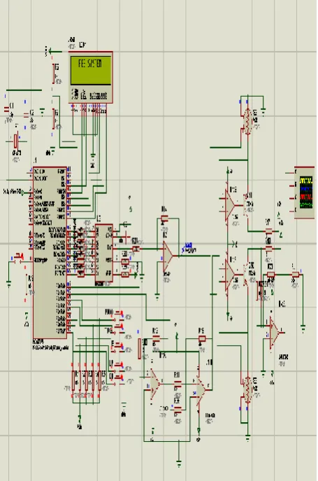
Fig. 3 shows the circuit diagram of main portion of FES using PIC Microcontroller. It has 5 push-button switches. Program button is used for mode selection and Trigger button is used to start stimulation. Whenever this button is pressed, stimulation starts for 60 seconds
In open-loop control mode, the remaining 3 push-buttons are used to set the parameters such as stimulation frequency, pulse width, inter-pulse duration and pulse amplitude. These parameters are stored in registers. Based on registers value, microcontroller generates symmetric biphasic pulses with inter-pulse interval by using timer 1 interrupt. These pulses
voltage with the help of 8-bit DAC. These current pulses are injected into paralyzed nerves through surface electrodes for muscles stimulation. Manual mode is used when the application is not critical. In this mode, patients themselves can set parameters with the help of instructions provided by doctors. This mode is generally used for minor muscle defects and does not use EMG instrument.
In closed-loop control mode, the severityof the muscle defect is understood from the EMGinstrument [7] whose electrodes are fixed with thepatient during the period of stimulation. The analog output ofEMG instrument is read by microcontroller
Controller Driving Stage Patient
current injection helps the muscles and nerves system to recover from the defect and the patient can move his legs for some longer period of time until the defect reformulates again.
3.2 SOFTWARE
[image:4.595.56.284.170.514.2]Software for microcontroller has been written in C language using MPLAB IDE 7.86 and PIC C compiler. After compilation of software, the HEX code has been loaded into microcontroller in the circuit diagram shown in Fig. 3 for simulation by using real time simulator Proteous 7.6..
Figure 3: Circuit Diagram of main portion of FES using PIC Microcontroller
Figure 4: Symmetrical bi-phasic with inter-pulse duration stimulus waveform
4. SIMULATION RESULT
The circuit diagram of proposed FES system has been made on real time simulator Proteous 7.6 as shown in Fig. 3. The stimulation parameters: stimulation frequency (1/T) = 100 Hz, pulse width (Tp) = 450 us, inter-pulse-duration = 200us and pulse amplitude = 30 mA are stored in PC at location 0x05. When microcontroller reads an analog data = 0.1V from EMG instrument, its 8-bit ADC converts this signal into corresponding digital value = 0x05. The controller sends this digital value to PC as an address through serial communication and reads the above parameters from PC. The output waveform generated on CRO corresponding to these parameters is shown in Fig. 4. The same waveform can be observed by setting the above parameters manually with the help of push button switches in open loop control mode.
5. CONCLUSION AND FUTURE WORK
A portable, programmable, battery-operated stimulator designed in this paper has been tested. It works according to the stated specifications. The most important technical features of the stimulator are simple programming with push-buttons manually in open loop mode as well as automatic programming with EMG feedback in closed loop mode. Thus one can use this stimulator for stimulation of minor muscles defect as well as critical muscles defect. In future, this stimulator can be designed using 16-bit microcontroller with 16-bit internal ADC to increase the resolution of analog data read from EMG instrument.6. REFERENCES
[1] Nikola Jorgovanović, Strahinja Došen and Ratko Petrović, “Novel Electronic Stimulator for Functional Electrical Therapy,” Journal of Automatic Control, University of Belgrade, vol.15(supplement), 2005.
[2] R. J. Weber, “Functional neuromuscular stimulation,” in Rehabilitation Medicine: Principles and Practice. Philadelphia, PA: Lippincott, 1993.
[3] R. B. Stein, M. Belanger, G. Wheeler, M. Wieler, D. B. PopoviC, A. Prochazka, and L. Davis, “Assessment of electrical stimulation system for improving locomotion after incomplete spinal cord injury,” Arch. Phys. Med. Rehab., vol. 74, pp. 954-959, 1993.
[4] K. W. Eric Cheng, Yan Lu, Kai-Yu Tong, A. B. Rad, Daniel H. K. Chow, and Danny Sutanto, Senior Member, IEEE, “Development of a Circuit for Functional Electrical Stimulation,” IEEE Transaction on Neural Systems and Rehabilitation Engg., vol. 12,No. 1, March 2004.
[5] Barry J. Broderick, Paul P. Breen and Gearóid ÓLaighin, “Electronic Stimulators for Surface Neural Prosthesis,” Journal of Automatic Control, University of Belgrade, vol. 18(2):25-33, 2008.
[6] Han-Chang Wu, Member, IEEE, Shuenn-Tsong Young, and Te-Son Kuo, Senior Member, IEEE, “A Versatile Multichannel Direct-Synthesized Electrical Stimulator for FES Applications,” IEEE Transaction on Instrumentation and Measurement, vol. 51,No. 1, February 2002.
[image:4.595.55.249.548.747.2]Processing, Classification and Applications”, Biological Procedures Online, vol. 8, issue 1, pp. 11–35 (2006).
[8] M. B. I. Reaz, M. S. Hussain, F. Mohd-Yasin, “Techniques of EMG Signal Analysis: Detection, Processing, Classification and Applications”, Biological Procedures Online, vol. 8, issue 1, pp. 11–35 (2006).
[9] R. B. Stein, M. Belanger, G. Wheeler, M. Wieler, D. B. PopoviC, A. Prochazka, and L. Davis, “Assessment of electrical stimulation system for improving locomotion after incomplete spinal cord injury,” Arch. Phys. Med. Rehab., vol. 74, pp.954-959,1993.
[10]T. Stieglitz, T. Matal, and M. Staemmler, “A modular multichannel stimulator for arbitrary shaped current pulses for experimental and clinical use in FES,” in Proc. 19th Int. Conf. IEEE EMBS, 1997, pp. 1777–1780. [11]C. J. Poletto and C. L. Van Doren, “A high voltage,
constant corrent stimulator for electrocutaneous stimulation through small electrodes,” IEEE Trans. Biomed. Eng., vol. 46, pp. 929–936, Aug. 1999.
[12]S. Simcox, S. Parker, G. M. Davis, R. W. Smith, and J. W. Middleton, "Performance of orientation sensors for use with a functional electrical stimulation mobility system," Journal of Biomechanics, vol. 38, pp. 1185-1190, 2005.
[13]M. R. Popovic and T. Keller, "Modular transcutaneous functional electrical stimulation system," Medical Engineering & Physics, vol. 27, pp. 81-92, 2005.
[14]T. Stieglitz, T. Matal, and M. Staemmler, “A modular multichannel stimulator for arbitrary shaped current pulses for experimental and clinical use in FES,” in Proc. 19th Int. Conf. IEEE EMBS, 1997, pp. 1777–1780.
7. AUTHORS PROFILE
Debabrata Sarddar is currently pursuing his PhD at Jadavpur University and Asst. Proff.in Kalyani University. He completed his M.Tech in Computer Science & Engineering from DAVV, Indore in 2006, and his B.Tech in Computer Science & Engineering from Regional Engineering College, Durgapur in 2001. His research interest includes wireless and mobile communication. Email: [email protected]
Madhurendra Kumar is presently pursuing M. Tech in Electronics Design and Technology at Tezpur University, Assam. He completed his B.E. in E.T.C.E. at Bangalore. His research interest is Embedded systems.