Orthogonal Phase Coded Waveforms for MIMO Radars
M. Harika Rao
Department of ECE GITAM Institute of Technology
GITAM University
G.V.K.Sharma
Department of ECE GITAM Institute of Technology
GITAM University
K. Raja Rajeswari
Department of ECE AU College of Engineering
Andhra University
ABSTRACT
Modern radar systems employ multiple transmit antennas on transmit and multiple receive antennas on receive to improve many aspects of the system performance including improved target detection performance, improved angle estimation accuracy, decreased minimum detectable velocity. However these advantages are obtained only when orthogonal probing waveforms are emitted from each of the transmit antenna elements. These waveforms further need to have good autocorrelation and crosscorrelation properties for good range resolution and multiple target return separability. Many previous works presented noise-like pseudo random phase coded waveforms with good correlation properties. However these waveforms suffered from limited family size, zero-lag non-orthogonality and hence non uniform distribution of transmit power in space. This paper presents the design of phase coded pulse waveforms with good correlation properties, zero-lag orthogonality property, delay and add property that support Doppler compensation, large family size, simpler generation, constant modulus etc.
Keywords
Multiple Input Multiple Output Radar, four phase waveforms, orthogonal transmit waveforms, uniform transmit beampattern
1.
INTRODUCTION
Radar systems transmit electromagnetic energy into free space and use the reflected energy to detect and locate desired targets of interest. Modern radar systems employ antenna array based transmit system and antenna array based receive system to improve many aspects of system performance. Multiple transmit antenna elements allow directive radiation of transmit power and multiple receive antenna elements allow directive reception of reflected echoes. The use of array based antenna systems allows angular parameters of the target to be determined accurately. Conventional phased array radars transmit fully coherent waveforms (possibly scaled by a complex constant) from their different transmit antenna elements forming a strong transmit beam in the desired direction. Beamforming is performed only by the receive array (containing antenna elements) to estimate the angular parameters of the target. Thus the transmit degrees of freedom are limited to one and receive degrees of freedom are . However multiple input multiple output (MIMO) radars transmit diverse waveforms from their different transmit antenna elements and use joint processing of the received signals from the different receive array elements. While phased array radars employ only spatial diversity, MIMO radars employ both spatial and waveform diversity to improve many aspects of system performance. MIMO radars can employ widely spaced antennas [1] or collocated antennas [2]. While the former configuration offers improved spatial diversity to improve target detection capabilities the latter configuration improves the spatial resolution, parameter
identifiability and interference rejection capability. However the above advantages are achieved only with orthogonal waveforms with good autocorrelation and crosscorrelation properties at all time lags.
Deng [3], Liu [4] have initially proposed polyphase sets based on genetic algorithm and simulated annealing respectively. However the size of the sequence sets is small and do not satisfy the orthogonality requirement. They also suffer from Doppler degradation. Hao and Stoica [5] have proposed unimodular sequence sets based on cyclic algorithm having continuous phases over the range [0,2π]. This makes generation of signals at the transmitter and design of matched filters at the receiver difficult. Hammad [6] addressed the Doppler problems of Deng sequences but still the size of the sequence family is limited. Singh [7] proposed a simulated annealing algorithm combined with hamming scan algorithm for designing eight phase sequence sets. However the size the sequence sets is small and using eight phase sequence sets introduces complex multiplications in the digital implementation of matched filters at the receiver. It is also commented in [3] that using polyphase sequences with number of phases does not yield a significant improvement.
2.
MIMO RADAR SIGNAL MODEL
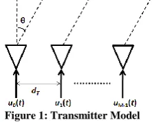
[image:2.595.114.225.129.218.2]Consider a monostatic MIMO radar that contains transmitters with the antenna elements configured as uniform linear arrays. We assume a point target and also that the target and transmitters lie in the same 2-D plane (see Fig. 1).
Figure 1: Transmitter Model
Let represent the spacing between consecutive transmitters. Let be the target angle with respect to the broadside direction and λ is the carrier wavelength of the transmitted waveforms. Let represent the transmitter waveforms. All the transmit antennas transmit waveforms simultaneously in time. We further assume that the transmitter waveforms are narrowband and the baseband signal waveforms are not modified because of Doppler effect [16]. The correlation between two transmit waveforms and at zero time-lag is defined as
(1) and represents the zero-lag correlation matrix of the transmit waveforms.
2.1
Phase Coded Pulse Waveforms
The phase coded pulse waveform emitted by the transmitter can be represented as
(2)
where
(3)
(4) Here represents the number of pulses emitted by each transmitter. Here, is the element of the code matrix and it can assume a value from the set is the duration of each pulse and is the duration of each subpulse. K is the phase number and represents the number of phases allowed by each polyphase waveform. Each row of the code matrix represents the phase code associated with each transmitted waveform. Each column of the code matrix corresponds to the phase code transmitted by each of the transmitters during the subpulse. As shown in Fig. 2, each transmitter waveform consists of a stream of identical pulses . Each pulse in turn contains phase coded subpulses each having width . For each of the transmitter waveforms to be orthogonal (at zero Doppler and zero delay mismatch) i.e.,
(5)
we require
(6)
[image:2.595.329.514.133.262.2]Orthogonal waveforms result in uniform illumination in all directions. For fixed , these waveforms can be completely described by the code matrix and the pulse spacings ( ).
Figure 2: Structure of Phase-Coded Pulse waveforms
2.2
Correlation Metrics
The aperiodic cross-correlation at a discrete shift between the phase code sequence and the phase code sequence is defined as
(7)
where denotes complex conjugate of the argument The aperiodic autocorrelation of at shift is the aperiodic cross-correlation of with itself
.
2.3
Problem Formulation
The goal of orthogonal polyphase signal design problem is to design the polyphase code set matrix
where each row represents an individual polyphase sequence used to transmit the phase coded pulse waveform . Each column represents the complex symbol transmitted in the subpulse, subject to minimization of the following criteria (in addition to satisfying the requirements (5) and (6)).
a) maximum AC peak sidelobe level
(8) b) maximum CC peak sidelobe level
(9)
2.4
Transmit Beampattern
The baseband signal at the target location can be described by the expression
(10)
(11) is the vector of transmit waveforms and is the array steering vector given by
(12) With typical transmitter spacing of , the spatial frequency is in . The spatial distribution of power of the transmit signals is called the transmit beampattern and is given by [8],
(13)
Consider for a phased array radar case. The transmit signal vector is given by where with denoting the steered direction. Then, assuming unit power signal and
(14) Note that the transmit gain attains maximum value in the direction and is decreased at Now, consider with orthogonal signals. Then, , and
(15) This implies that the beampattern is omnidirectional. Thus, the traditional beamforming results in a focused beampattern while the beampattern of MIMO with orthogonal signals is uniform in all directions.
3.
FOUR PHASE CODE GENERATION
Sequences with good autocorrelation properties can be generated by using pseudo noise generators called maximal length sequences. When it is desired to generate a binary m-sequence of period , one looks up a table of binary irreducible polynomials of degree and then selects from amongst the table, an irreducible polynomial that is also primitive. The procedure for generation of four-phase sequences is very similar. Given that it is desired to generate the family with size of four phase sequences of period , one proceeds as follows. First, identify polynomials with coefficients in that are irreducible as binary polynomials when their coefficients are reduced modulo 2 (i.e. irreducible over Z2). It is easily shown that these polynomials are also irreducible over Z4. Next, from amongst these pick a primitive polynomial ; An irreducible polynomial of degree is said to be primitive if the smallest exponent for which the polynomial divides is . Complete listings of all primitive polynomials having degree ≤ 10 are listed in [11]. Table-I below provides partial listing of primitive polynomials given in [11] for reference. Note: For degree 3, the entry 1213 represents the polynomial .
Table 1: Partial Listing of Characteristic Polynomials for Linear Recurrence
Degree 3 1213, 1323 Degree 4 10231, 13201
Degree 5 100323, 113013, 113123, 121003, 123133 Degree 6 1002031, 1110231, 1211031, 1301121 Degree 7 10020013, 10030203, 10201003 Degree 8 100103121, 100301231, 102231321 Degree 9 1000030203, 1001011333, 1001233203
3.1
Signal Generation
Given a primitive polynomial
(16) with coefficients , the sequence in the family can be generated from the linear recursion associated with given by
[image:3.595.317.544.239.360.2]
(17) over . By initializing the linear recursion with different initial states and evaluating the linear recursion we get cyclically distinct sequences in family each of length . The linear recurrence described above can be efficiently implemented using the shift register configuration shown in Fig. 3.
Figure 3: Shift Register implementation of family A as generated
by characteristic polynomial
. All addition,
multiplication and negation operations follow modulo-4 arithmetic
3.2
Example
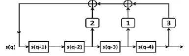
Consider the degree polynomial , primitive as a Z4 polynomial. By reducing the coefficients modulo 2, one obtains the binary primitive polynomial . We notice that . This implies . The linear recurrence given by is defined as
[image:3.595.332.525.520.577.2]This linear recurrence can be implemented using the shift register configuration shown in Fig. 4. Cyclically distinct members of the family can be found by loading the shift register with 4-tuples not previously seen during the generation of prior sequences
Figure 4: Shift Register implementation of family A as generated by characteristic polynomial
The above recurrence yields the family of Z4 sequences of size 17 (24+1) and signal length 15 (24-1).
[image:3.595.49.284.663.759.2]
Polyphase sequences can now be obtained from the above sequences by mapping the elements in Z4 to .
4.
CODE OPTIMIZATION AND
NUMERICAL RESULTS
The four phase codes discussed in the preceding section are shown [9] to have good aperiodic autocorrelation and aperiodic crosscorrelation properties. However the sequences are do not satisfy the orthogonality property. This results in non-uniform illumination of power in space. The property of orthogonality between the every pair of sequences is one of the key requirements of MIMO radars.
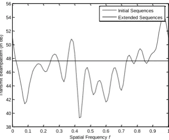
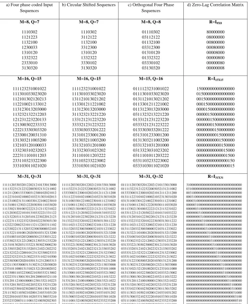
[image:4.595.68.240.598.740.2]Popovic and Suehiro [10] showed that there exist a “circular phase shift” for each of these sequences that result in zero-delay crosscorrelation of any two distinct sequences in this set is -1. If a 1 is preprended to each sequence in this set, then the zero-delay crosscorrelation of any pair of distinct sequences in this set will be zero. The zero-delay autocorrelation of each of these sequences is however (where is the initial sequence length). The generated four phase sequences are circular shifted to obtain a zero-delay correlation of -1 with all the other sequences in the matrix. The example of the shifted versions of the input sequences generated has been shown in the second column of Table-2. These shifted sequences are prepended with a 0 in order to obtain the zero-lag correlation matrix as zero. So the zero-lag correlation matrix will have the diagonal elements to be equal to the number of elements in each sequence and the other elements in the matrix to be zeros. This is illustrated in the zero-lag correlation matrix column as shown in Table-2. Therefore the correlation between any two sequences in the matrix is now zero. Hence the property of orthogonality has been achieved along with the good autocorrelation and crosscorrelation properties. The transmit beampattern (5) of MIMO radar transmit array with M=16 elements (waveforms) as a function of spatial direction (frequency ) of initial sequences and code optimized orthogonal sequences is displayed in Fig. 5. We see that the transmit beampattern of waveforms using initial sequences generated using (17) is nonuniform whereas the code optimized sequences have a uniform beampattern which is desirable in MIMO radar systems.
Figure 5: Transmit Beampattern
5.
CONCLUSIONS
This paper presents the construction of four phase pulse coded waveforms for MIMO radar applications. The advantages of the proposed method includes large family size, constant modulus, near optimal auto and cross correlation properties, pair wise orthogonality of sequences for uniform transmit beampattern etc.
This work can be further extended to identify eight phase sequence sets based on ML sequence generators and finite field theory. Since MIMO radars suffer from directive gain loss each waveform emitted by each transmit antenna need to have long pulse width to maximize the transmit energy and further the received SNR. Sequences of any required length can be generated by selecting the primitive polynomial of appropriate order.
6. REFERENCES
[1] Haimovich, A. M., Blum, R.S., Cimini, L. J., MIMO Radar with Widely Separated Antennas, IEEE Signal Processing Magazine, vol.25, Issue 1, pp.116-129, Sept. 2008.
[2] Jian Li and P. Stoica, MIMO Radar with Colocated Antennas IEEE Signal Processing Magazine, vol.24, no.5, pp.106-114, Sept. 2007.
[3] Hai Deng, Polyphase code design for orthogonal netted radar systems, IEEE Transactions on Signal Processing, Vol-52, No-11, November 2004.
[4] Bo Liu, Zishu He, Jiankui Zeng, Benyong Liu, Polyphase Orthogonal Code Design for MIMO Radar Systems, Proc. 2006 CIE Int. Conf. Radar, Oct. 2006.
[5] Hao He, Petre Stoica, Jian Li, Designing Unimodular Sequence Sets With Good Correlations for MIMO Radar, IEEE Transactions on Signal Processing, Vol-57, No-11, November 2009.
[6] H. A. Khan and D. J. Edwards, Doppler problems in orthogonal MIMO radars, Proc. IEEE, Int. Radar Conf., April 2006, pp. 24–27.
[7] S.P. Singh, S.A Muzeer, K. Subba Rao, Eight -phase Sequence Sets Design for Radar, WSEAS Trans. Sig. Proc, Mar. 2009.
[8] D. Fuhrmann, G. San Antonio, Transmit beamforming for MIMO radar systems using signal cross-correlation, IEEE Trans. Aerospace Electron. Syst. 44(1) pp:171– 186, Jan. 2008.
[9] Sharma, G. V. K., and K. Raja Rajeswari. "Four-phase orthogonal code design for MIMO radar systems." Communications (NCC), 2012 National Conference on. IEEE, 2012.
[10]Branislav M. Popovic´, Naoki Suehiro, Pingzhi Z. Fan, Orthogonal Sets of Quadriphase Sequences With Good Correlation Properties, IEEE Transactions on Information Theory, Vol 48, No. 4, April 2002.
[11]S.Boztas, R.Hammons and P.V.Kumar, 4-Phase sequences with near optimal correlation properties, IEEE Transactions on Information Theory IT-38 No-3, May 1992. 1101-1113.
0 0.1 0.2 0.3 0.4 0.5 0.6 0.7 0.8 0.9 1 38
40 42 44 46 48 50 52 54 56
Spatial Frequency f
Tr
a
n
s
m
it
B
e
a
m
p
a
tt
e
rn
(
in
d
B
)
Table 2: a) Four Phase Sequences generated using the linear recursion of (6) b) Circular Shifted Sequences of (a) for optimal zero-delay crosscorrelation c) Orthogonal Sequences with a zero-delay cross correlation of 0 between any pair of distinct
sequences d) Zero-Delay cross correlation matrix of each pair of sequences
a) Four phase coded Input Sequences
b) Circular Shifted Sequences c) Orthogonal Four Phase Sequences
d) Zero-Lag Correlation Matrix
M=8, Q=7 1110302 1121223 1132100 1230033 1310120 1332322 2333010 3130320 M=8, Q=7 1110302 3112122 1132100 3312300 1310120 1332322 3330102 3130320 M=8, Q=8 01110302 03112122 01132100 03312300 01310120 01332322 03330102 03130320 R=I8X8 80000000 08000000 00800000 00080000 00008000 00000800 00000080 00000008 M=16, Q=15 111123231001022 111301033023020 112101302120213 112210021133012 113123013203000 113232132212203 121231223220133 121300302233332 122213330303320 123300120031310 131303211003200 132103120100033 133230310232023 222311101011203 233110323322300 333103011021020 M=16, Q=15 111123231001022 111301033023020 131121013021202 113301211221002 113123013203000 311323213221220 133121231223220 333321231223222 133303033201222 313101233001200 131303211003200 331321031201000 313323031023202 311101011203222 331103233223002 333103011021020 M=15, Q=16 0111123231001022 0111301033023020 0131121013021202 0113301211221002 0113123013203000 0311323213221220 0133121231223220 0333321231223222 0133303033201222 0313101233001200 0131303211003200 0331321031201000 0313323031023202 0311101011203222 0331103233223002 0333103011021020 R=I15X15 15000000000000000 01500000000000000 00150000000000000 00015000000000000 00001500000000000 00000150000000000 00000015000000000 00000001500000000 00000000150000000 00000000015000000 00000000001500000 00000000000150000 00000000000015000 00000000000001500 00000000000000150 00000000000000015 M=31, Q=31 1111120330320122021210133013000 1111322312122322003032131211002 1112112001333300312300102021012 1112231010210002103231303102013 1112310023131100330122100223010 1113100112302122203030111033020 1113302130100322221212113231022 1121203022210101310332221331122 1121322031131203101223022012123 1122231133223323201022230303130 1123223200232101132112203311102 1123302213113203323003000032103 1131322110100120203010313213200 1133100310320320003012333031222 1133302332122120021230331233220 1213101302031333221303023000230 1213303320233133203121021202232 1221323221220010123132330023333 1222232323312130223331102310300 1223303003202010301312312003313 1232113033000313130231232030020 1233101100013131021321201002032 1313300110322300221030333213002 1322233113001301201200010321110 1331201121001000012301332110223 1331320130322102203232133231220 1333102330102302003230113013202 2311130211030210200121033103120 2322201010333011020333130033210 2333233200311110013210030202303 3333201101203220232303110310003 M=31, Q=31 1111120330320122021210133013000 1111322312122322003032131211002 1333300312300102021012111211200 1311122310102100021032313031020 3131100330122100223010111231002 1113100112302122203030111033020 1113302130100322221212113231022 1331122112120302221010131033222 3113120310122302201212311213220 3113322332320102223030313011222 3311102112322320023210113211220 1311320332300300003210311233022 1131322110100120203010313213200 1133100310320320003010313213222 1133302332122120021230331233220 3133322130302300023012131013020 3313320312102120223212133033202 3333122132322122001012313233002 3331102310300122223232331213022 3313122330300320201030131231200 3131302312320300201232113033000 1313102132120100203212331011000 1313300110322300203210333213002 3311300130120100221032111013222 3133120112100100001230133211022 1331320130322102203232133231220 1333102330102302003230113013202 3111302110302102001210331031202 3331300332102322201010333011020 3111100132100302023032333233200 3333320110120322023230311031000 M=31, Q=32 01111120330320122021210133013000 01111322312122322003032131211002 01333300312300102021012111211200 01311122310102100021032313031020 03131100330122100223010111231002 01113100112302122203030111033020 01113302130100322221212113231022 01331122112120302221010131033222 03113120310122302201212311213220 03113322332320102223030313011222 03311102112322320023210113211220 01311320332300300003210311233022 01131322110100120203010313213200 01133100310320320003010313213222 01133302332122120021230331233220 03133322130302300023012131013020 03313320312102120223212133033202 03333122132322122001012313233002 03331102310300122223232331213022 03313122330300320201030131231200 03131302312320300201232113033000 01313102132120100203212331011000 01313300110322300203210333213002 03311300130120100221032111013222 03133120112100100001230133211022 01331320130322102203232133231220 01333102330102302003230113013202 03111302110302102001210331031202 03331300332102322201010333011020 03111100132100302023032333233200 03333320110120322023230311031000 R=I31X31 31000000000000000000000000000000 03100000000000000000000000000000 00310000000000000000000000000000 00031000000000000000000000000000 00003100000000000000000000000000 00000310000000000000000000000000 00000031000000000000000000000000 00000003100000000000000000000000 00000000310000000000000000000000 00000000031000000000000000000000 00000000003100000000000000000000 00000000000310000000000000000000 00000000000031000000000000000000 00000000000003100000000000000000 00000000000000310000000000000000 00000000000000031000000000000000 00000000000000003100000000000000 00000000000000000310000000000000 00000000000000000031000000000000 00000000000000000003100000000000 00000000000000000000310000000000 00000000000000000000031000000000 00000000000000000000031000000000 00000000000000000000000310000000 00000000000000000000000031000000 00000000000000000000000003100000 00000000000000000000000000310000 00000000000000000000000000031000 00000000000000000000000000003100 00000000000000000000000000000310 00000000000000000000000000000031
[image:5.595.49.552.114.727.2]