Validation of UML Class Model through Finite-State
Machine
Vipin Saxena
Department of Computer Science Babasaheb Bhimrao Ambedkar University
(A Central University) Viday Vihar, Rae Bareli Road Lucknow (U.P.),226025, INDIA
Santosh Kumar
Department of Computer Science Babasaheb Bhimrao Ambedkar University
(A Central University) Viday Vihar, Rae Bareli Road Lucknow (U.P.),226025, INDIA
ABSTRACT
The Unified Modeling Language (UML) is an independent to programming language which has a collection of modeling tools through which software engineers and researcher represent the complex research problems in the diagrammatic form. The various tools represent the static as well as the dynamic behavior of an object-oriented software system. The state chart diagram is a well known tool of UML which shows the dynamic behavior of states of an object-oriented system. The entire life of an object is represented by this tool. The state transformation of an object is depending on the three major components like transition function, action and possible inputs. The paths through which an object changes its state are determined by the state chart diagrams. These paths can be represented in the graphical form with the use of Finite State Machine (FSM). The graphical representation is very useful for determining the correctness of the diagram. In the present work, an approach to validate the UML class model through FSM is described with a creation of the transition table. For testing purpose, some test cases are generated to test the correctness of UML state chart diagram by taking a real case study of Life Insurance Corporation (LIC) of India. An approach to verify the correctness of UML diagram is presented.
Keywords
UML, FSM, Class Diagram, State Diagram, Transition Table.
1.
INTRODUCTION
Object Management Group (OMG) has released a standard modeling language for the scientific community for designing the object oriented systems and given a new definition for the modeling of any object-oriented system especially for solution of the complex research problems. The name of this language is Unified Modeling Language known as UML and became very popular in the present scenario.
It is a well known modeling language which provides a lot of modeling tools and graphical notations for solving complex the object-oriented problems in the field of software engineering. It also provides standardization in specifying, documenting, writing blueprint and visualizing the artifacts of
the state chat diagrams which is one of the most versatile tools for describing the life cycle of an object from its initialization to termination. State chart diagrams represent the dynamic behavior of any software system in graphical form, which shows all the paths through which an object changes its state during its entire life and these paths further graphically represented by the use of the concept of Finite State Machine (FSM).
FSM gives a computational model for dynamic as well as static behavior of any software system. It is an abstract machine that produces a finite number of states and it produces one state at a time by reading input symbols. The working of FSM is started from the initial state and end on the final state and it can accept any length of string; if an automaton reaches its final state by reading input symbols one by one otherwise it rejects the string. The input is a finite set of alphabets. The finite-state automata can accept or reject an input string.
their use. Chow T. S. [10] has proposed a method of testing the correctness of control structures that can be modeled by a finite-state machine. Clifford E. C. [11] has proved the RTL coding styles for efficient and synthesizable Finite State Machine (FSM) design using IEEE-compliant Verilog simulators. Bilung Lee and Edward [12] have focused on the interaction of FSMs and three concurrency models: synchronous dataflow, discrete-event and synchronous reactive models.
In the present work, a UML state diagram is converted into FSM through which the test cases are generated for a real case study of Life Insurance Corporation of India (LIC) for issuing the policy to the handicapped people. Test cases are generated for the validation of UML class model and suitable production rules are also designed.
2.
UML CLASS MODEL FOR ISSUING
POLICY FOR HANDICAPPED
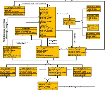
The UML Class model of issuing policy for handicapped is presented here through the UML class model concepts. There are eight major classes with their attributes are represented in figure 1. The model shows the process of issuing policies for the handicapped person. The Customer class has multiple associations with the Plan, New_Business, Medical_Office, Disability and Mobile_System; the customer chooses a plan and fills the policy proposal form. The New_Business checks
the policy proposal form and refers the customer to the Medical_Officer for medical purpose or if the customers have not fulfill the eligibility criteria then the New_Business class rejects the policy proposals. The Medical_Officer examines the customer and gives the medical report with percentage of disability. The New_Business verifies the disability of the customer as given by the medical officer and issues a policy according to the percentage of disability; if the percentage of disability ≤ 60% then the policy is issued by the LIC_Branch and deposits the premium amount of the issued policy in the Main_Branch through the Bank and if the percentage of disability > 60% then the Customer is referred to the Main_Branch for issuing policy. All the LIC_Branch offices are inheriting the functionality of New_Business, Medical_Officer, Main_Branch and all the Banks associated with all the LIC_Branch are also inheriting the functionality of Bank. The premium amount of the policy is auto deducted by the Main_Branch through the Bank which is linked to the every LIC‟s branch. The class Bank sends the confirmation of payment amount to the Main_Branch and then Main_Branch sends the confirmation of issuing the proposed policy on the customer‟s Mobile_System and also sends a hard copy payment receipt policy bond. The customer‟s data is uploaded online through the software and also stored in the LIC‟s database. The details and the status of the policy can be viewed through any hand held devices like smart phones, PDA‟s, Laptop, etc via internet.
+Verify_Applicatios() +Refer_to_MO() -Officer_ID -Officer_Name -Designation -Mobile_No -Address New_Business +Confirm_Disability() +Percentage_of_Disability() -Doctor_ID -Doctor_Name -Designation -Mobile_No -Address Medical_Officer +Issue_policy() +Notifications() -Division_Code -Branch_Code -Branch_Office_Add Main_Branch +....() -Cust_Code +Cust_Name -Plan_Code -Plan_Term -Policy_No -Premium_Term -Date_of_Comm -Date_of_Birth +Sex -Medical_Status -Earning -Income p/a +Address -Mobile_No -Premium_Mode -Premium_Due_Date -Date_of_Maturity -Age_at_Maturity -Naminee -Age -Relation Customer +..() -Plan_Code +Plan_Type Plan +Hand_Held_Device() +Recieve_Notifications() -Mobile_No -IEMI_No -Service_Provider Mobile_System +Issue_policy() +Notifications() -Branch_Code -Division-Code +Branch_Office_Add LIC_Branch_1 +Deposit_premium() -Branch_Code -Bank_Name -Branch_Office_Add Bank +Issue_policy() +Notifications() -Branch_Code -Division_Code +Branch_Office_Add LIC_Branch_2 +Issue_policy() +Notifications() -Branch_Code -Division_Code +Branch_Office_Add LIC_Branch_N-1 +Issue_policy() +Notifications() -Branch_Code -Division_Code +Branch_Office_Add LIC_Branch_N +..() -Disability_Code -Type_of_Disability -Percentage_of_Disability Disability +..() -Plan_Code -Plan_Name Insurance_Plan +..() -Plan_code -Plan_Name Special_Plan +..() -Plan_Code -Plan_Name Pension_Plan +..() -Plan_code -Plan_Name Withdrawl_Plan --- ---* 1 * 1
Interacts with information
* *
*
1
Sends confirmation regarding policy
Auto deduct premium amount Select the plan
C he ck s t he p ro po sa l & re fe r t o M ed ic al of fic er o r r ej ec t i f n ot el ig ib le Examine the disability * * * * 1 * * * * *
[image:2.595.117.476.402.709.2]Verify the % of disability If d isa bili ty > 60 % 1 * * * * *
3.
FUNDAMENTALS OF FSM
In the theory of automata, the finite state machine is also known as deterministic finite automata or simply it is a mathematical model used to design computer program and digital logic circuits. A finite state machine „M‟ is defined as:
M = (Q, Ʃ, δ, q0, F)
Where
Q denoted as a finite set of state in finite state machine;
Ʃ denoted as a finite set of input symbols, these symbols may be any alphabets or numbers;
A transition function is denoted by δ that takes as arguments a state and input symbol and returns a state. In the graph representation of an automata, δ is represented by an arcs between two states and label of arcs. If q is a state and a is an input symbol, then δ (q, a) is that state p such that there is an arc labeled a from q to p2;
q0 is denoted as initial state, which is one of the state of
Q;
F is a set the final or accepting state, the set of F is a subset of Q;
From the above definition of automata, a finite state machine is constructed, whose states correspond to the variable Q and all the input symbols & transition in the system are corresponding to the variable Ʃ and δ, respectively. The initial state of the system is q0, which is one of the states in Q. Thus
from the above definition, the different form of state machine and its equivalent transition table are generated.
3.1
Conversion of State Transition
Diagram into FSM
The state transition diagram is illustrated by taking a sample state chart diagram of Login Window which is shown below in the figure 2:
Login Winodw a User Name b Password
Enter user name Enter password
a' if Wrong user name
[image:3.595.360.529.119.215.2]b' if Wrong password Start/Stop
Figure 2: UML State Diagram of Login Window
From the above state diagram, it is assumed that entering a user name and password either „a‟ or „b‟ is an event. With the help of above state diagram authors have drawn a finite state machine according to UML state diagram. The transition
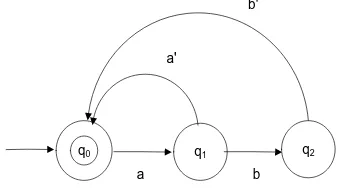
The equivalent finite state machine of the above UML state diagram is as shown in figure 3:
q1
q0 q2
a b
a' b'
Figure 3: Finite State Machine for Login window
From the above FSM, q0 is an initial as well as the final state
which shows the login window, q1 = enter the user name and
q2 = enter the password. The transition table for the above
[image:3.595.323.536.331.469.2]finite state machine is created which shown as table 1:
Table 1. Transition Table for Login Window
State/ Input „a‟ „a´‟ „b‟ „b´‟
*→q0 q1 - - -
q1 - q0 q2 -
q2 - - - q0
3.2
Case Study of Issuing Policy for
Handicapped
[image:3.595.60.272.529.681.2]Customer
New_Business Medical_Officer
Main_Branch Bank
Proposal for policy
Refer for Medical
Verify the % of Disab If % of
Disab <= 60%
If % of Disab
> 60% Deposit Premium amount Issue a
policy Reject if not
eligible
Deposit Premium amount
LIC_Branch
[image:4.595.320.539.73.264.2]Confirmation of payment Start/Stop
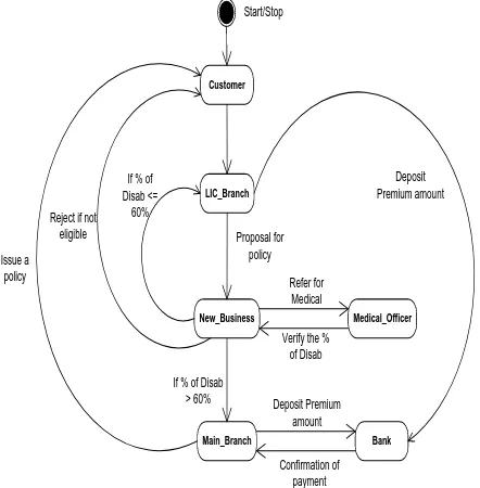
Figure 4: State Diagram of Issuing Policy for Handicapped
In this case it is assumed that the Customer is the initial as well as the final state of opening policy, this state is equivalent to „q0‟ and the Customer goes to the New_Business
with the policy proposal in LIC_Branch. When the Customer proposes a policy in LIC_Branch, the state is changing say „a‟ to “LIC_Branch” state (q1) and „b‟ to “New_Business” state (q2). Here New_Business verifies the policy proposal and goes back to the final state with the message of not eligible say „b″‟ or goes to the next state for medical if eligible with message verifies and refers for medical say „c‟. After verifying the policy proposal system goes into the new state called Medical_Officer (q3). When the Medical_Officer examines and confirms the disability say „c′‟ of Customer then system goes back to the New_Business (q2). Now New_Business checks the percentage of disability of the Customer, if the percentage of disability is less than or equal to 60% say „b′‟ then the policy is issued by the LIC_Branch and system will enter into the loop state called „q1‟, and if the percentage of disability is greater than 60% say„d‟ then the policy is issued by the Main_Branch and system will enter into the new state called „q4‟. After issuing the policy, the premium amount is deposited by the Main_Branch and LIC_Branch say „f‟ and „e‟ into the Main_Branch account and system will enter into the new state called „q5‟. As depositing the premium amount the bank confirms the payment say „g‟ and system goes back into the state „q4‟. After getting the confirmation of premium payment the Main_Branch issues a policy say „h‟ and handed over the policy bond with the premium deposit receipt. The finite state machines for issuing policy for handicapped in LIC of India through the set of these states equivalencies can be drawn as shown in the figure 5.
q1 q2
q0 q3 q4 q5
b' b"
c' h
a b c
d
f g
[image:4.595.57.278.74.299.2]e
Figure 5: Finite State Machine of Issuing Policy for Handicapped
From the above FSM, the transformation of states from one state to another state on the basis of {a, b, b′, b″, c, ……… h} events. These events are considered as terminals for the above finite state machine of issuing policy for handicapped in LIC of India, and the set of states {q0, q1,
q2, q3, q4, q5} are assumed to be non-terminals for the above
machine, where q0 is the initial as well as the finale state of
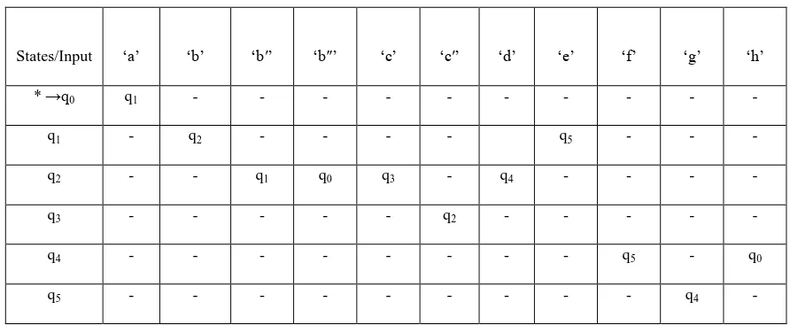
the above finite state machine of issuing policy for handicapped in LIC of India. The various productions can be induced for the above finite state machine and the corresponding transition table is as shown below in table 2:
q0 → a q1
q1 → bq2
q1 → eq5
q2→ cq3
q2 → b′q1
q2 → b″q0
q2 → dq4
q3 → c′q2
q4→ fq5
q4→h q0
Table 2. Transition Table for Issuing Policy for Handicapped
States/Input „a‟ „b‟ „b′‟ „b″‟ „c‟ „c′‟ „d‟ „e‟ „f‟ „g‟ „h‟
* →q0 q1 - - - -
q1 - q2 - - - - q5 - - -
q2 - - q1 q0 q3 - q4 - - - -
q3 - - - q2 - - - - -
q4 - - - q5 - q0
q5 - - - q4 -
For verification of the above production rules, some test cases are generated and described below in brief:
3.2.1
Test Case 1
The LIC has not issue a policy, if the eligibility criteria is not fulfill by the customer. As shown in the above figure 5, there is no direct path from state q0 to q4. So, the state q0 must pass
through the states q1 and q2 for issuing a policy.
3.2.2
Test Case 2
The New_Business validates the policy proposals after verifying the medical status which is given by the medical officer or the policy proposal is rejected if the eligibility criterion is not fulfill by the customer. This can be verified by the following productions:
q2 → cq3
q2 → b ″
q0
q3 → c′q2
3.2.3
Test Case 3
The policies are issued by the LIC_Branch and Main_Branch according the disability condition, if the disability ≤ 60% then the policy is issued by the LIC_Branch and if the disability > 60% then the policy is issued by the Main_Branch. The following productions verify these aspects:
q2 → b′q1
q2 → dq4
3.2.4
Test Case 4
The premium amount of all issued policies is auto debited in the LIC Main_Branch‟s account through the bank. The following productions are verifying it:
q1 → eq5
q4→ fq5
3.2.5
Test Case 5
The confirmation of premium payment and issuing policy is given by the following production:
q5→ gq4
q4→h q0
4.
CONCLUDING REMARKS
From the above work, it is concluded that UML is a powerful modeling language for modeling the various kinds of the research problems and one can depict the static as well as the dynamic behavior of the system. Since, software professionals are converting their old structured based designs in the form of object-oriented designs due evolution of graphical user interface applications, therefore, UML is widely used by many researchers and software professionals for proposing the object-oriented designs. The above work is based upon the presentation of validation technique through FSM for the UML models which show the dynamic behavior of the system. The proposed model for issuing the policies to the handicapped person is validated through various test cases drawn from the FSM.
5.
ACKNOWLEDGMENTS
Thanks are due to University Grants Commission, New Delhi, for providing Rajiv Gandhi National Fellowship (RGNF) to carry out the above research work.
6.
REFERENCES
[1] OMG, “Unified Modeling Language Specification”, http://www.omg.org (Accessed on 12th Sept. 2012), 1997.
[2] OMG, “Unified Modeling Language (UML)–Version 1.5”, OMG document formal/2003-3-01, (2003), Needham, MA.
[3] G. Booch, J. Rumbaugh and I. Jacobson, “The
Unified Modeling Language user Guide”,
[4] G. Booch, J. Rumbaugh and I. Jacobson, “The Unified Modeling Language User Guide”, China Machine Press, Beijing, 2006.
[5] Hopcroft, J.E., Ullmann J.D., “Introduction to Automata Theory”, Languages, and Computation, Addison-Wesley, 1979.
[6] Lee D., Yannakakis M., “Principles and Methods of testing Finite State Machines- A Survey”, Proceeding of the IEEE, Vol. 84, No. 8, 1996, pp. 1090-1126.
[7] Luo G., Von Bochmann G., Petrenko A.F., “Test
Selection based on Communicating
Nondeterministic Finite State Machines using a
Generalized Wp-Method”, IEEE Trans
Software Engineering Vol. 20, No. 2, 1994, pp 149-162.
[8] C. J. Mallery, “On the Feasibility of Using FSM Approaches to Test Large Web Applications”, May 2005.
[9] E. Roche and Y. Schabes, “Introduction to Finite-State
Devices in Natural Language
Processing”, Mitsubishi Electric Research Laboratories, June 1996, (Accessed on http://www.merl.com).
[10] Chow T. S., “Testing Software Design Modeled by Finite State Machines”, IEEE Transactions on Software Engineering SE-4, 3(1978), 178- 187.
[11] Clifford E. Cummings, “The Fundamentals of Efficient Synthesizable Finite State Machine Design using NC-Verilog and BuildGates”, International
Cadence User Group 2002 San Jose, CA, Rev 1.2.
[12] Bilung Lee and Edward A. Lee, “Interaction of Finite State Machines and Concurrency Models”, Proceeding of Thirty Second Annual Asilomar Conference on Signals, Systems, and Computers, Pacific Grove, California,