Optimized Asynchronous Circuit Design based on
Evolutionary Algorithm
Masoud Shiroie
M.Sc. Student
Department of Electrical Engineering, Iran University of Science and Technology, Tehran,
Iran
Karim Mohammadi
Full Professor
Department of Electrical Engineering, Iran University of Science and Technology, Tehran,
Iran
ABSTRACT
Remarkable advantages of asynchronous circuits in comparison with their synchronous counterparts results in vast effort in designing such circuits. This paper proposes optimized asynchronous circuit design approach by exploiting potent evolutionary circuit design method. The evolutionary algorithm applies fast and accurate hazard detection technique as a fitness function. Outcomes of proposed method in designing fundamental mode asynchronous circuit in comparison with previous methodologies reveal its notable advantages like, multi level circuit design with lower number of gates which results in lower area, lower power consumption and lower cost. Experimental result demonstrate that the proposed method reduces number of gates about 16.81%.
General Terms
Computer aided design, Asynchronous circuit, Hazard free design.
Keywords
Hazard, Evolutionary algorithm, Burst mode machine, Asynchronous, Genetic programming.
1.
INTRODUCTION
Research interest in Asynchronous circuit design is associated from their marvelous advantages in contrast with synchronous circuits like, no clock skew, low power, robustness to environmental variation, great modularity and average case instead of worst case performance [1,2,3,4]. Unlike salient progress in synchronous circuit design method and CAD tools, asynchronous circuit design methods are not developed noticeably because of difficultly in hazard-free circuit design. Hazard free output of asynchronous circuit guaranties accurate response of circuit in absence of clock signal.
This inevitable problem in asynchronous circuit design plus its advantages encourages researchers to propose a lot of methods in hazard free circuit design. Mcclusky and Unger proposed a method to design type of circuit which works accurately in presence of single-input change (SIC) [5]. Frackowiak addressed an algorithm which eliminates dynamic hazard at the first step and at the second step eliminates the static hazards. Consequently the proposed method may result in a design which is not optimum [6]. In 1992 Kung proposed a hazard-non increasing optimization algorithm to optimize hazard free circuits [7]. The exact two-level minimization is proposed by Nowick and Dill in 1995 which is not able in multi-level design [8]. New methodology is proposed in [9] which suffers from bounded wire delay constraint. A heuristic method is developed by Theobal et all in order to reduce designing time. Their proposed method can produce a two level hazard-free circuit in presence of multiple-input changes
and Brekelear in 1998 which was faster than Theobald’s method [11]. Binary decision diagram is used in [12] in order to design multi-level hazard free circuit considering MIC by unbounded gate and wire delay model assumption. Synchronous technology mapping technique is used to design generalized fundamental mode asynchronous circuit [13]. All above approaches suffer from some disadvantages and constraints like bounded wire and gate delay model, two phase algorithm, dedicated hazard free algorithm and demand to synchronous technology mapping tool. Consequently this paper proposes an evolutionary algorithm based design which doesn’t suffer from such a problem. This paper is organized as follows. Section 2 provides brief introduction to hazard, delay models and applied hazard detection technique. In section 3 applied evolutionary algorithm is described. Experimental result is presented at section 4. Finally proposed method is concluded in section 5.
2.
BAKGROUND KNWOLEDGE FOR
THE PROPOSED METHOD
2.1
Hazard and delay models
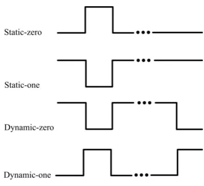
Fig 1: Types of hazardous signals
Delay of signal transition in gate and wire is causer of logic hazard. There are some types of delay model which results in different methodology in hazard free circuit design. Pure delay model is simplest delay model which shifts the signal in time without changing its shape. High frequency response for gates and wires is assumed in pure delay model. There is more realistic model which is known as inertial delay model. Inertial delay model suppresses short pulses. Pure delay model can be itemized by delay time but inertial delay model needs reject time as well. Pulses shorter than reject time will not be seen at output of gate in inertial delay model. Both mentioned delay model can be specified based on types of assumed delay time. The fixed delay model is specified by constant delay time. In min-max delay model, delay time can be within lower and upper bound. There is a pessimistic delay model in which each gate can has unknown and infinite delay time. Unbounded gate delay model results in speed independent circuit design. Finally the most pessimistic delay model assumes unbounded delay for both wire and gate which is origination of delay insensitive circuits [16]. Pure delay and inertial delay with fixed delay time need an explicit delay information which is not usually available in practical fabrication process. The same transition in inputs of an AND gate by different delay models can result in different output which is shown in figure 2 (a) and figure 2 (b). As shown in figure 2 (a) the AND gate with mentioned transitions at inputs will results in hazardous output. But same input transitions will not cause hazardous signal at output of AND gate, because reject time is longer than pulse width in output .Shifted pulse in output of AND gate in figure 2 (c) indicates that delay time can be within an specified bound. Hazard analysis with unbounded delay model assumption will result in pessimistic decision on hazard detection as shown in figure 2 (d). In figure 2 (d) if the falling transition happens prior to rising transition the output cannot be estimated as hazard-free signal because of being short of timing information.
t=5 t=1
Delay time=5
t=6 t=10
t=5 t=1
Delay time=5
t=6 t=10
t=5 t=1
Delay time=[3 7]
t=6 t=10
t=? t=?
Delay time=[0 infinite] t=? t=? Reject time=6
(a)
(b)
(c)
(d)
Pure delay with fixed delay
time
Pure delay with min-max delay
time Inertial delay
with fixed delay time
[image:2.595.322.536.73.348.2]Unbounded delay time
Fig 2: Effect of delay model in hazard analysis
2.2
Hazard detection technique
[image:2.595.316.543.605.736.2]All evolutionary algorithm like Genetic, particle swarm optimization (PSO) and etc use fitness function to evaluate each member of population. Consequently our evolutionary algorithm uses number of hazardous signal at output of circuit as part of a fitness function. Three value algebra is the first nonboolean algebra which is used in hazard detection approaches. The three value algebra is unable in detecting dynamic hazard. After that another multi-value algebras like, four, five, six, eight, nine, thirteen and 27-value algebras are proposed to surmount imperfect previous algebras [17]. All these hazard detection method are capable of analyzing both combinational and sequential hazards. But in our case, the simple and fast hazard detection method which is adequate enough for our scope in combinational hazard detection is applied. Micheal and Tragoadas proposed a fast and simple hazard detection method for combinational hazard detection under unbounded gate and wire delay model [18]. Our hazard detection technique uses eight value logic truth table. Figure3 shows values which is used in eight value logic truth table.
In this paper two input standard gates are applied for design. Therefore eight value logic truth tables are defined for standard two input gates like, AND, NAND, NOT, OR, NOR, XOR and XNOR. Truth table for NOT gate is
1 8
[image:3.595.319.516.78.158.2]dimension unlike other gates because of its single input. Table 1 indicates truth table for a two-input AND gate. Table 2 and 3 demonstrate truth table for NOT and OR gates respectively. The eight value truth table for each gate is generated considering unbounded delay model. For example, in table 1, AND gate with input signal like R and F will result in S0 without considering their sequences. This pessimistic approach is because of unbounded delay model which results in lack in timing information.
Table 1. Eight value truth table for two-input AND gate
AND 0
1
R
F
S0 S1 D0 D1
0
0
0
0
0
0
0
0
0
1
0
1
R
F
S0 S1 D0 D1
R
0
R
R
S0 S0 D1 S0 D1
F
0
F
S0
F
S0 D0 D0 S0
S0
0 S0
S0 S0 S0 S0 S0 S0
S1
0 S1 D1 D0 S0 S1 D0 D1
D0
0 D0 S0 D0 S0 D0 D0 S0
D1
0 D1 D1 S0 S0 D1 S0 D1
Table 2. Eight value truth table for NOT gate
Input
0 1 R F S0 S1 D0 D1
Output
1 0 F R S1 S0 D1 D0
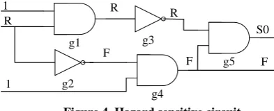
[image:3.595.57.276.236.370.2]The hazard detection technique starts from primary inputs and continues to reach outputs. Output of each gate is being extracted from its own truth table corresponding to its inputs. Output of each gate feeds inputs of gates from next level. This method continues until all outputs are considered. This methodology is illustrated in figure 4. The primary inputs are {1,R,1}. The hazard detection algorithm starts from primary inputs and extracts output of g1 by referring to table 1 as truth table of AND gate. Output of g2 is calculated at the same way by using truth table of NOT gate. This method extracts outputs of g3 and g4 by using outputs of previous step as inputs. Finally the output of g5 is concluded.
Table 3. Eight value truth table for two-input OR gate
AND
0
1
R
F
S0 S1 D0 D1
0
0
1
R
F
S0 S1 D0 D1
1
1
1
1
1
1
1
1
1
R
R
1
R
S1 D1 S1 S1 D1
F
F
1 S1
10 D0 S1 D0 S1
S0
S0 1 D1 D0 S0 S1 D0 D1
S1
S1 1 S1
S1
S1 S1 S1
S1
D0
D0 1 S1 D0 D0 S1 D0 S1
D1
D1 1 D1 S1 D1 S1 S1 D1
g1 g3
g4 1
R
1
R
g5 F R
S0
F
g2 F
Figure 4. Hazard sensitive circuit
3.
PROPOSED METHOD
The hazard detection technique as a fitness function is described in previous section. The rest of our evolutionary method is going to be explained here. All evolutionary algorithm based circuit design methods suffer from stalling limit and CPU time. These problems are considered in [19, 20, 21, 22, 23]. To overcome these problems our evolutionary algorithm uses Cartesian genetic programming (CGP) which is presented by Walker and Miller in [24]. The CGP have some characteristics which results in some advantages. In CGP programming each node can be connected to each previous node. Thereby function and modules which are developed by previous levels of circuit can be reused easily. CGP uses rectangular grid of nodes which can be specified by number of rows and columns. In previous works, it is proved that CGP with one row will performs efficiently. Consequently our EA is based on CGP with one row and N columns which N is maximum number of node in circuit. N is summation of M inputs, S outputs and N-(M+S) internal nodes. Each node in CGP consist of integers which defines function of node and its connection to previous nodes. For example a circuit with its corresponding CGP chromosome is shown in figure 5. Number of internal nodes begins with M and ends with N+M-1. In figure 5 each gate is coded by unique integer. AND, OR, NAND and XOR gates are defined by 3, 4, 8 and 7 respectively. Number of nodes are started by 0 which is assigned to first input. The depicted CGP chromosome in figure 5 contains nodes for each gate. Each nodes is composed of three integers which two first integers show connection of node and third integer in bold format shows function of node. CGP is capable of having neutral nodes which is shown by dashes in circuit of figure 5. Our EA is based on famous
1
method where
is size of population. Steps of applied EA is demonstrated in Figure 5. At the first step,
chromosomes are initiated randomly. Fitness of each chromosome will be calculated based on equations (1) and (2) in second step.4 0
1
2 3
5
6
7
8 Input 0
Input 1
Input 2 Input 3
Output 0
0 1 3 2 3 4 0 4 7 4 5 8 6 5 3 8
4 5 6 7 8 Output 0
Figure 5. example of designed circuit with CGP and its corresponding chromosome
0 0
1 0, 1, 0 1
,
0 0, 1, ,
T O
t j
output S S D or D
NH h h
output R or F
[image:3.595.327.531.587.676.2]1 2 3
F
K
NH
K
NG
K NFO
(2)Where h is indicator of hazardous signal at outputs, t is number of transitions at inputs, O is number of outputs, NG is number of gates which is used to design circuit. NFO is number of faulty output which is derived by considering circuit definer truth table. Purpose of this method is designing a circuit with NH equal to zero, NFO equal to zero and NG as lower as possible. The mentioned conditions guaranties circuit with hazard free behavior, accurate functionality and optimum design respectively. K1, K2 and K3 are weight percent
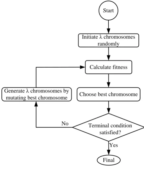
coefficients which are tuned in order to have a fitness function which results in faster evolutionary algorithm. Bigger K1 in contrast with K2 and K3 will result in an EA which tries to find an answer with propriety to hazard free behavior. In order to pay attention to designing circuit with accurate functionality, K3 should be bigger with respect to other weight percent coefficients. If the EA cannot find an optimized answer with lower number of gates, the problem can be diminished by increasing K2. Chromosome with lower fitness will be selected as best chromosome at the third step. If the terminal condition is not satisfied next generation of chromosomes will be created by mutating best chromosome, else the algorithm terminates and best chromosome will be reported as designed circuit. The final and best answer must not have any faulty output which can be translated to accurate functionality. Additionally the best answer is not allowed to have hazardous behavior at outputs. Algorithm can be terminated by reaching constant number of iteration, sticking in iterations without any improvement in fitness or combination of both.
Start
Initiate λ chromosomes randomly
Calculate fitness
Choose best chromosome
Terminal condition satisfied? Generate λ chromosomes by
mutating best chromosome
Final No
[image:4.595.52.295.409.693.2]Yes
Figure 6. Flowchart of evolutionary algorithm
4.
PERFORMANCE EVALUATION
The proposed algorithm is implemented by C language. The algorithm is evaluated by executing on some famous
0 0.25 0.5 0.75 1 1.25 1.5 1.75 2 2.25 2.5 2.75 3 3.25 3.5 3.75 4 4.25 4.5 4.75 55 0.5
1 1.5 2 2.5 3 3.5x 10
5
Mutation rate
N
um
be
r of i
te
ra
ti
on
[image:5.595.107.489.78.279.2](3.5,87180) Minimum number of iteration
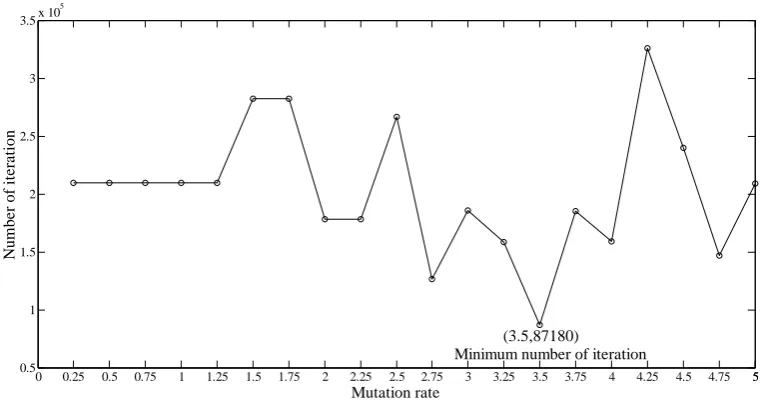
[image:5.595.130.465.315.484.2]Figure 7. Number of iteration versus mutation rate by Averaging ten times execution for dme-e example circuit
Figure 8. Number of gates used to design burst mode machines
[image:5.595.127.468.510.692.2]5.
CONCLUSION
An Evolutionary based hazard free circuit design method is developed. The proposed method uses fast and accurate hazard detection technique. The applied hazard detection technique uses eight value truth table in order to model hazardous behavior of each gate. The formulated fitness function in our evolutionary algorithm is summation of number of hazardous signal at outputs, number of faulty output and number of used gates. The accurate and best answer of evolutionary algorithm does not have faulty outputs. The best answer of EA does not show hazardous behavior at outputs and has lowest number of gate. These condition guaranties hazard free circuit with accurate functionality and minimum number of gates. The proposed method does not need any timing information about gates and wires because of unbounded gate and wire delay assumption in hazard detection technique. Additionally the proposed EA does not have any constraint in number of level in circuit. Consequently the designed circuit can be multi level. The improvement about 16% in decreasing number of gates demonstrate that the proposed method can find some answers which is not found in previous classic methods.
6.
REFERENCES
[1] Hauck, S. “Asynchronous design methodology: an overview”, In Proceeding of the IEEE, Vol. 83, No. 1, pp. 69-93,
[2] J. Sparso, S. Furber “Principles of asynchronous circuits design – a system perspective”, Springer Publisher, 2001.
[3] P. A. Beerel and T. Meng, “Automatic gate-level synthesis of speed independent circuits”, IEEE International Conference on Computer-Aided Design, pp. 581-586, Nov. 1992.
[4] E. Brunvand, R. F. Sproull, “Translating concurrent programs into delay-insensitive circuits,” IEEE International Conference on Computer-Aided Design, pp. 262-265, NOV. 1989.
[5] S. H. Unger, “Asynchronous sequential switching circuits”, New York Wiley-Interscience, 1969.
[6] J. Frackowiak, “Methoden der analyse und synthese von hasardarmen schaltnetzen mit minimalen kosten I,” Elektronische Informationsverarbeirung und Kyberneitik, vol. 10, no. 213, pp. 149-187, 1974. [7] D. S. Kung, “Hazard-non-increasing gate-level
optimization algorithms,” IEEE International Conference on Computer-Aided Design, pp. 631-634, 1992.
[8] S. M. Nowick, D. L. Dill “Exact two-level minimization of hazard-free logic with multiple-input changes”, IEEE Transactions on Computer-Aided Design of Integrated Circuits and Systems, vol. 14, no. 8, August 1995.
[9] L. Lavagno, K. Keutzer, and A. Sangiovanni-Vincentelli, “Algorithms for synthesis of hazard-free asynchronous circuits,” In ACM/IEEE Design Automation Conference, pp. 302-308, 1991.
[10] M. Theobald, S. M. Nowick, T. Wu, ”Espresso–hf: a heuristic hazard–free minimizer for two–level logic”, pp. 71–76, 1996.
[11] J. Rutten, M. Berkelaar, “Efficient exact and heuristic minimization of hazard-free logic,” In Proceeding of International Conference of Computer Design (ICCD), pp. 152–159, 1998.
[12] B. Lin, S. Devadas, “Synthesis of hazard-free multi-level logic under multiple-input changes from binary decision diagrams,” In proceeding of International Conf of Computer-Aided Design (ICCAD), pp. 542– 549,1994.
[13] F. Shi, “Removing hazards in multi-level logic optimization for generalized fundamental-mode asynchronous circuits”, IEEE International Conference on Computer Design, pp.640-645, 2008.
[14] E. C. Tan, M. H. Ho, “Matrix method to detect logic hazards in combinational circuits with EX-OR gates”, Journal of Universal Computer Science, vol. 5, no. 11 , pp. 765-776, 1999.
[15] I. Beister, “A unified aproach to combinational hazards”, IEEE Transaction on Computers, pp. 566-575, June 1974.
[16] Jens Sparsø, ” Asynchronous circuit design”, Technical University of Denmark, 2006.
[17] J.A. Brzozowski, Z. Esik, Y. Iland ,“Algebras for hazard detection”, 31st IEEE International Symposium on Multiple-Valued Logic, pp.3-12, 2001
[18] M.K. Michael, S. Tragoudas, “Generation of hazard identification functions”, Fourth International Symposium on Quality Electronic Design, pp. 419- 424, 24-26 March 2003.
[19] I. Kajitani, T. Hoshino, M. Iwata, Higuchi, T. Higuchi, “Variable length chromosome GA for evolvable hardware”, IEEE International Conference on Evolutionary Computation, pp. 443-447, 1996.
[20] E. Stomeo, T. Kalganova, C. Lambert, “Generalized Disjunction Decomposition for Evolvable Hardware,” IEEE Transactions on Systems, Man, and Cybernetics, Part B: Cybernetics, vol.36, no.5, pp.1024-1043, 2006. [21] T. Higuchi, M. Murakawa, M. Iwata, I. Kajitani,
Weixin Liu, M. Salami, “Evolvable hardware at function level”, IEEE International Conference on Evolutionary Computation, pp. 187-192, 1997.
[22] J. Lee, J. Sitte, “A gate-level model for morphogenetic evolvable hardware,” IEEE International Conference on Field-Programmable Technology, pp. 113-119, 2004. [23] J. Lee and J. Sitte, “Gate-level Morphogenetic
Evolvable Hardware for Scalability and Adaptation on FPGAs,” First NASA/ESA Conference on Adaptive Hardware and Systems, pp. 145-152, 2006.
[24] J. A. Walker, J. F. Miller, “The automatic acquisition, evolution and reuse of modules in Cartesian genetic programming “, IEEE Transactions on Evolutionary Computation, vol. 12, pp. 397-417, 2008.