Generating all Navigational Test Cases using
Cyclomatic Complexity from Design Documents for
Mobile Application
Ayan Nigam
Quality & Process Lead, Ideavate Solutions,
Indore, India
Bhawna Nigam
Department of Information Technology, Institute of Engineering & Technology, DAVV, Indore
Devendra Kumar Vatsa
Department of Computer Engi. Institute of Engineering & Technology, DAVV, Indore
ABSTRACT
This is new mobile world; lots for even the simplest mobile application there can be many Navigational Paths. The challenge at Design phase is to identify all possible paths, generate code and validations for each one of them. Generating all possible test paths and test cases are difficult to achieve and need lot of manual efforts. In this paper we tried to generate possible navigational path using Design documents, so that Development and QA team get all the possible number of test cases in Design Phase itself. This will help to Estimate and analyze the actual project scope and timeline. QA Team save time as they do not have to generate paths manually and thereby reducing Navigational bugs getting detected and ensuring enhanced Path Coverage.
General Terms
Test cases, Cyclomatic Complexity, Navigational Path, Mobile Application, Design Document.
1.
INTRODUCTION
In this new era of mobile world navigational mobile application are largely used for various tasks. In mobile application, number of pages is connected & provides functions for end user. End user can easily navigate mobile applications which are interconnected. Due to small nature of mobile application it is less costly for end users & there are thousands of users so a regress testing is required before launching of mobile application, because a small bug can affect all those end users.
Testing is the important process of SDLC for bug detection & test case generation. In developing a mobile application Client (Stakeholder) provide requirement for Design Documents & According to clients requirement Designer develops the Design Documents. There are so many methodology & tools available for testing the mobile applications when application is already developed. Even there is Lack of testing methodology at the time of design phase for mobile application. Testing of Design Documents manually can arise lots of error by human mistakes. This entire problem arise a need of methodology which can test mobile application at design time. This paper contains mobile applications navigational testing during design phase to generate number
of test cases at design time. With the help of this testing other stakeholders can also decide number of team members & cost for developing application.
A navigational mobile application is organized & the pages are linked by the designer as user perceptive. According to client requirements when an activity is performed designer linked pages of mobile application. When an activity is preformed on mobile node by end user pages or links are navigated. Each node functions as a specialized path or link to relay information to other nodes. Organization of collection of pages is decided at the time of design phase when part of code is not available Testing becomes even more harder in organized systems mainly due to unavailability and also maintenance go at a faster rate than other software systems and this maintenance often consists of small incremental changes.
There are several methodological and technological proposals for developing test case generation tool of mobile application (MA) are coming both from industry and academia at the time of testing phase, but there is a lack of general methods and tools to carry out the key processes that significantly impact the quality of a mobile application (MA), such as the Validation & Verification (V&V), at early phase of SDLC (a similar dictation is proposed by Dr.Giuseppe Antonio Di Lucca, Dr. Anna Rita Fasolino, Dr.Francesco Faralli & Dr.Ugo De Carlini [1]). The structure of Design Documents is an activity diagrams, which is often one strongly connected component as a whole. Analysis of Design Documents visually shown that one activity depends on another. Back edges and hyperlinks providing alternative navigations are quite common, making the resulting structure close to a fully connected graph. [2] This design document can contained various paths for navigation. With the help of this design documents created navigational dependency graph (NDG) can be created which can generate all number of test path that can be calculated by cyclomatic complexity number. In other words, when the structure of the MA is strongly connected, loop probabilities tend to make the contribution of new navigational test cases for test path.
designer by executing tested object with selected node input values & navigational path. MA typically undergo maintenance at a faster rate than other software systems and this maintenance often consists of small incremental changes[3]. Small incremental increase enhance designer effort if designer tested, design documents manually Navigation-Based Testing (NBT) is a type of testing strategy that depends on extracting test cases from different navigational dependency graph.NDG is created by three models: requirements models, usage models, and models constructed from activity [4].NDG used Cyclomatic Complexity [5] Proposed by Dr.McCabe give complexity structure of NDG & number of test path in Design Documents.
In this methodology all possible navigational test cases is generated using cyclomatic complexity theory, for generating all navigational test cases first the navigational dependency graph is created with all the intermediate stages. Using this cyclomatic complexity number all possible test paths has been identified. With the help of this identified test path all possible test cases will have generated.
Architecture Model of Proposed System
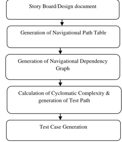
Fig1. Shows the architecture of test case generation system.
.
Fig 1: Architecture of test case generation system
2. EXPLANATION OF ARCHITECTURE
[image:2.595.352.531.81.354.2] [image:2.595.56.254.359.590.2]A. Design Document: - storyboards are one of the design documents designed for mobile application. According to client requirement designer create storyboards that can be understood by all other stack holders.
Fig 2. Storyboards for message box registration.
Fig2 shows the Storyboards for message box registration in mobile application. In this application user have a main screen for message box registration .In main screen either user can successfully submit registration form and will switch to inbox or user have a security check for registration in the form of verification mail. If verification mail is successfully sent then user will again switch for inbox or will switch to error pages. In this application user will switch for exit from inbox & error pages.
3. GENERATION OF NAVIGATIONAL
PATH TABLE
According to storyboard of designer navigational testing strategy created a table. This table shows name of storyboards screen. User will enter the value of node & their name & testing strategy generate navigational dependent node table. For example in Table1 node value A shows main screen & node value J shows Exit.
Table1. Navigational dependent Node
i=0 Node Value Node Name N(i)
1 A Main Screen
2 B Inbox
3 C Create An Account
4 D Registration form
5 E Registration form not successfully submitted
6 F Page for errors
7 G Go to the Error display page
8 H Submit
9 I Verification mail sent to phone no. Or email id (If successful submission)
10 J Exit
Generation of Navigational Path Table
Generation of Navigational Dependency Graph
Calculation of Cyclomatic Complexity & generation of Test Path
Test Case Generation Story Board/Design document
Submit Main Screen
Create an Account
Inbox
Registration form not submitted Registration
Form
Page for errors
Go t
o error display page Verification mailsent
or not sent to email idTable 2 the design document of navigational application is used to automatically generate the Navigational Path table (NPT) with all the Navigational activities involved in it including decisions, loops and synchronization.
Table 2. Navigational dependency Path
No
. P[] Node
Navigational Path Activity
Dependency node
1 P[1] B BA A
2 P[2] B BH H
3 P[3] B BI I
4 P[4] C CA A
5 P[5] D DC C
6 P[6] E ED D
7 P[7] E EI I
8 P[8] F FE E
9 P[9] G GF F
10 P[10
] H HD D
11 P[11
] I IH H
12 P[12
] J JG G
13 P[13
] J JB B
The aims of these table (1&2) is showing the activities that having transfer in control to otherentities which can be useful for system, regression and integration testing. It also includes the input node and the expectedoutput dependent values for each navigational activity. Dependency of each activity on others is clearly shown in NPT through navigational path activity. Example of NPT describe that node B has three dependent nodes A, H & I & their respective paths are BA, BH & BI. Similarly node J has two dependent nodes G & B and their respective paths JG & JB. When generate navigational dependency graph table is generated 1 describe node values of storyboard screen name & table 2 is used for generated dependent activity for all nodes.
4. GENERATION OF NAVIGATIONAL
DEPENDENCY GRAPH
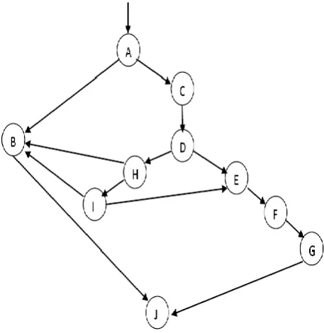
The navigational path table is used to automatically generate the navigational dependency graph of Design Documents of application. Fig3. Show generated navigational dependency graph. In NDG node values is used for screen name & each node represents an activity to other node for relaying information. Since repeated activities are given the same symbol in the navigational dependency table, only one node is created for them no matter how many times they are used in the design. This will decrease the search space in the navigational dependency graph. The transitions from one activity to another are represented by edges in the NDG. The presence of an edge from a node to another is determined by checking the dependency column in the Table 2 for the current node‟s symbol. Specifically, if it contains the previous node‟s symbol then an edge from the previous node to the current one is drawn in the NDG. Otherwise, we backtrack in the NDG until finding the node whose symbol is mentioned in the current Node‟s dependency column and create an edge
[image:3.595.54.281.137.373.2]from it to the current node and so on until all the rows in the NPT are finished. Synchronization, decisions and loops are demonstrated using edges as well.
Fig 3. Navigational Dependency Graph
In our example, after creating nodes for all the symbols mentioned in the NPT we start creating the edges. Since the symbol „A‟ is the first symbol in the NPT, then it is made at the root node with no dependencies assigned to it. Then comes symbol „B‟ to become the current node after dependent Later to B i.e., we check the dependency column of node „B‟ and compare its registered values with all the other symbols .Finding nodes „A‟, ‟H‟, and „I‟ means that a transition edge should be drawn from each one of them to the current node „B‟ and will continue for all other nodes till all nodes completed.
Graph to Adjacency matrix
Fig 3 is a directed graph. Using this graph the following matrix: It has 10 vertices and 13 edges.
Table 3: Adjacency Matrix of figure 3
Adjacency matrix shows successive path when 1 if the edge is there, & „0‟ if no edge is there. Between two nodes adjacency.
[image:3.595.319.549.555.680.2]Calculation of Cyclomatic complexity & test path
Cyclomatic Complexity is proposed by Thomas J. McCabe is a means of measuring the complexity of a given graph. Complexity is measured by counting „decision‟-the more decisions i.e. number of statement/loops in the graph what is the meaning of decision. A graph goes through in a single run. McCabe‟s Cyclomatic metric, V (G) of a graph "G" with "n" vertices and "e" edges is given by the following formula.
CCN=V-N+2
=13-10+2 =5
This cyclomatic complexity number define that the graph has 5 decision test paths which are now traversing is using DFS.
Graph traversing is perform using DFS
Step-1: Set the starting point of traversal and push it inside the stack.
Step-2: Pop the stack and add the popped vertex to the list of visited Test Path.
Step-3: Find the adjacent vertices for the most recently visited vertex.
Step-4: Push these adjacent vertices inside the stack (in the increasing order of their depth) if they are not visited and not resent there in the stack already.
[image:4.595.320.547.235.773.2]Step-5: Move to step-2 if the stack is not empty move to go to step 1 else step 1 and repeat until all the traversal paths are complete.
Table 4. Test path
Test Path Test Cases
Test Path1 A->B->J
Test Path2 A->C->D->E->F->G
Test Path3 A->C->D->H->B->J
Test Path4 A->C->D->D->H->I->B->J
Test Path5 A->C->D->H->I->E->F->G->J
Table4 shows that are 5 test paths that for navigational dependency graph according to cyclomatic complexity number. When traversing is performing node A is stored in stack then Node B & finally Node J. Here are decision is completed according to cyclomatic complexity number. This stack is placed on Test Path1. Again when traversing is performed it starts from node A to C, D, E, F and G & store the node information in test path 2and stack in test path 2 continue for all five test paths.
Total Number of test cases
Total number of test cases is generate with the help of summations of all test path node & cyclomatic complexity number .Test path 1 contain 3 nodes ,Test path 2 contain 5 nodes & when cyclomatic number subtracted from those test paths result gives total number of test cases as shown in table 5 are 32.
(TestPath1+TestPath2+TestPath3+TestPath4+TestPath5) - (CyclomaticComplexity Number) = Total number of test cases.
Table 5: Total number of Test case
Navigational Test Path Node
CCN Total no of Test case= P[j]-CCN
32 5 27
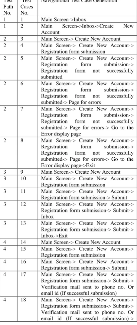
B. Test Case Generation:-
Table 6 contain 3 columns one for test path number & other two for test case number & navigational test case generation respectively. Traversing of test path produces test node values. For each node assign it‟s respective screen name from table 1 & traverse all test cases, put this value in column navigational test case generation of table6.
Test Path No.
Test Cases No.
Navigational Test Case Generation
1 1 Main Screen->Inbox
1 2 Main Screen->Inbox->Create New Account
2 3 Main Screen-> Create New Account 2 4 Main Screen-> Create New Account->
Registration form submission
2 5 Main Screen-> Create New Account-> Registration form submission-> Registration form not successfully submitted
2 6 Main Screen-> Create New Account-> Registration form submission-> Registration form not successfully submitted-> Page for errors
2 7 Main Screen-> Create New Account-> Registration form submission-> Registration form not successfully submitted-> Page for errors-> Go to the Error display page
2 8 Main Screen-> Create New Account-> Registration form submission-> Registration form not successfully submitted-> Page for errors-> Go to the Error display page->Exit
3 9 Main Screen-> Create New Account 3 10 Main Screen-> Create New Account->
Registration form submission
3 11 Main Screen-> Create New Account-> Registration form submission-> Submit 3 12 Main Screen-> Create New Account->
Registration form submission-> Submit-> Inbox
3 13 Main Screen-> Create New Account-> Registration form submission-> Submit-> Inbox->Exit
4 14 Main Screen-> Create New Account 4 15 Main Screen-> Create New Account->
Registration form submission
4 16 Main Screen-> Create New Account-> Registration form submission-> Submit 4 17 Main Screen-> Create New Account->
Registration form submission-> Submit-> Verification mail sent to phone no. Or email id (If successful submission) 4 18 Main Screen-> Create New Account->
[image:4.595.47.290.432.505.2]Inbox
4 19 Main Screen-> Create New Account-> Registration form submission-> Submit-> Verification mail sent to phone no. Or email id (If successful submission)-> Inbox->Exit
5 20 Main Screen-> Create New Account 5 21 Main Screen-> Create New Account->
Registration form submission
5 22 Main Screen-> Create New Account-> Registration form submission-> Submit 5 23 Main Screen-> Create New Account->
Registration form submission-> Submit->Verification mail not sent to phone no. or email id
5 24 Main Screen-> Create New Account-> Registration form submission-> Submit-> Verification mail not sent to phone no. or email id-> Registration form not successfully submitted
5 25 Main Screen-> Create New Account-> Registration form submission-> Submit-> Verification mail not sent to phone no. or email id....> Registration form not successfully submitted-> Page for errors 5 26 Main Screen-> Create New Account->
Registration form submission-> Submit-> Registration form not successfully submitted-> Verification mail not sent to phone no. or email id-> Registration form not successfully submitted-> Page for errors-> Go to the Error display page 5 27 Main Screen-> Create New Account->
Registration form submission-> Submit-> Registration form not successfully submitted-> Page for errors-> Go to the Error display page->Exit
[image:5.595.57.287.560.653.2]
5. EXPERIMENT RESULT
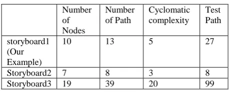
Table 6 shows Experiment result of different storyboards test paths.
Table6. Experiment Result
Number of Nodes
Number of Path
Cyclomatic complexity
Test Path storyboard1
(Our Example)
10 13 5 27
Storyboard2 7 8 3 8
Storyboard3 19 39 20 99
Table6 Experiment results define a clear view of analysis result of storyboards. We have analysis 3 storyboards for generating & calculating Navigational test cases. Results of 3 Story boards provide accurate number of navigational node, navigational path. Our result also provides complexity & navigational test case generation value for all those Design Documents.
6. CONCLUSION
Many researchers and practitioners have been working in generating optimal test cases based on the Specifications still 100% testing is impossibility .Navigational testing is new subject arising in navigational system. There are many testing algorithms for testing phase & for developing phase where code is integral part of testing. Rather than requirement of navigational testing system is an important factor for new era of mobile world. This is new proposed technique so, there may be next steps of future work will include generating the scenarios based testing for generating each test case automatically, based on the information given in the Design Documents description.
7. REFERENCES
[1] Giuseppe Antonio Di Lucca, Anna Rita Fasolino, Francesco Faralli, Ugo De Carlini “Testing Web Applications” Proceedings of the International
Conference on Software Maintenance
(ICSM.02),Napoli,Italy,2002
[2] Paolo Tonella and Filippo Ricca, “Statistical testing of Web applications” Journal of Software Maintenance and Evolution: Research and Practice, Trento, Italy, 2004 [3] Zhongsheng Qian, Zhongsheng Qian, Hongwei Zeng, “A
Practical Web Testing Model for Web Application Testing” Third International IEEE Conference on Signal-Image Technologies and Internet-Based System, Shangai, China, 2005
[4] Pakinam N. Boghdady, Nagwa L. Badr, Mohamed Hashem and Mohamed F.Tolba,”A Proposed Test Case Generation Technique Based on Activity Diagrams”, International Journal of Engineering & Technology IJET-IJENS Vol: 11 No: 03, june 2011
[5] Martin Sheppard,” A critique of cyclomatic complexity as software metric”, Software Engineering Journal, England, March, 1988
[6] L. Luo. “Software Testing Techniques, Technology Maturation and Research Strategies”, Class Report, Institute for Software Research International, Carnegie Mellon University, Pittsburgh, USA, 2009.
[7] A.C. Dias-Neto, R. Subramanyan, M. Vieira, G.H. Travassos. “A Survey on Model-based Testing Approaches: A Systematic Review”, Proceedings of the 1st ACM international workshop on Empirical assessment of software engineering languages and technologies in conjunction with the 22nd IEEE/ACM International Conference on Automated Software Engineering (ASE), New York, USA, 2007.
[8] A.C. Dias-Neto, G.H. Travassos. “Model-based testing approaches selection for software projects”, Journal of Information and Software Technology 51 (2009). [10] S.K. Swain, D.P. Mohapatra, R. Mall. “Test Case
Generation Based on Use case and Sequence Diagram”, International Journal of SoftwareEngineering, IJSE 3 (2010).