International Seminar on the Application of Science & Mathematics 2011 ISASM 2011
TUNABILITY PERFORMANCE OF REFLECTARRAY
ELEMENTS BASED ON ANISOTROPIC SUBSTRATES
M. Hashim Dahriand M. Yusof Is ma il
Radio Communications and Antenna Design Laboratory, Department of Communication Engineering, Faculty of Electrical & Electronic Engineering, University Tun Hussein Onn
Malaysia, 86400 Parit Raja, Johor, Malaysia [email protected]
Reflectarray antennas combine some of the best features between parabolic reflector and phased array antennas, but their application in satellite and terrestrial systems is limited due to high reflection loss performance and limited phase ranges.In this paper an X-band reflectarray patch ele ment constructed on 1mm thic k anisotropic liquid crystal substrateis proposed to be employed as a dynamic phase control strategy for terrestrial systems. Re flect ion loss and tunability characteristics of dipole and rectangular patch elements, printed on different anisotropic liquid crystal substrates have been investigated by using CST computer model. A detailed analysis of static and dynamic phase ranges with respect to dielectric anisotropy is presented for different anisotropic liquid crystal substrate materials. The preliminary simu lated results demonstrate that dipole patch element contributes h ighest reflection loss performance of 33.51d B compared to rectangular patch element which offe rs ma ximu m reflection loss of 10.74dB, by using K-15 ne matic liquid crystal as dielectric substrate. The numerical Finite Integral Method analysis shows that dipo le patch ele ment printed above novel LC mixture offe rs ma ximu m static and dynamic phase ranges of 210° and 290° respectively, co mpared to rectangular patch ele ment which o ffers ma ximu m static and dynamic phase ranges of 182° and 230° respectively. The die lectric an isotropic properties of liquid c rystal materia ls presented in this work are shown to significantly affect the reflection loss and phase range performance of reflectarray antennas for rapid dynamic phase change which was required particularly for s atellite and terrestrial systems.
Keywords: Reflectarray, terrestria l systems, patch element, dielectric anisotropy, liquid crystal, tunability, dynamic phase range, Fin ite Integral Method.
1. INTRODUCTION
2. REFLECTARRAY DESIGN
Various types of anisotropic liquid crystal substrate materials, listed in Table 1, are used to design different types of X-band reflectarray patch elements such as dipole and rectangular, constructed on 1mm thick anisotropic substrate resonating at 10 GHz. The numerical Finite Integral Method (FIM) has been used to investigate the reflection loss and tunability characteristics of dipole and rectangular patch elements by using commercially available CST computer model.
3. SIMULATED RESULTS, DISCUSSION AND COMPARISON
3.1 Reflection Loss
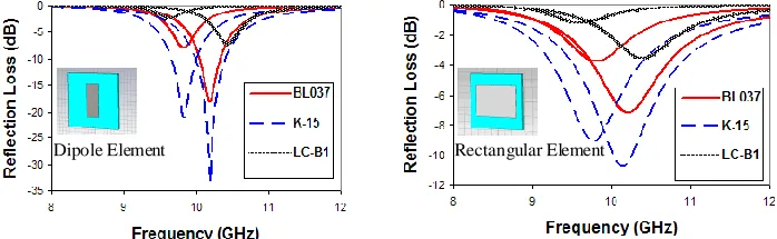
Anisotropic materials have a range of dielectric permittivity values. The minimum and maximum dielectric permittivity values are considered here for each material, therefore each material holds two different values for reflection loss operating at 10 GHz. The reflectivity performance of reflectarray antenna with dipole and rectangular patches is shown in Fig. 1. It has been shown from Fig. 1 that dipole element contributes almost 3 times higher losses as compared to the rectangular element, as discussed in [7]. Table 2 summarizes the maximum (for ε┴) reflection loss values for dipole and rectangular
[image:2.596.121.495.142.250.2]elements respectively. As depicted in Table 2, it has been observed that dipole element offers highest reflection loss performance of 33.51 dB compared to rectangular element which offers maximum reflection loss of 10.74 dB, by using K-15 nematic liquid crystal as dielectric substrate.
Fig. 1. Ma ximu m reflection loss curves of dipole and rectangular ele ments
(
Δ r = r║ - r )Merck - BL006 2.2 2.38 0.18 0.056 0.036
Merck - BL037 2.25 2.45 0.2 0.048 0.025
K15 Ne mat ic 2.1 2.27 0.17 0.072 0.06
LC-B1 2.6 3.05 0.45 0.022 0.007
LC M ixture [5] 2.39 3.18 0.79 0.0061 0.0016
Novel LC M ixture [6] 2.5 3.4 0.9 0.01 0.0035
[image:2.596.132.481.573.681.2]International Seminar on the Application of Science & Mathematics 2011 ISASM 2011
Table 2. Ma ximu m reflection loss comparison of dipole and rectangular ele ments .
3.2 Static and Dynamic Phase Ranges
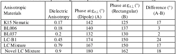
The reflection phases of dipole and rectangular elements for some anisotropic liquid crystal materials are shown in Fig. 2. As depicted in Fig. 2 it has been observed that dipole element offers steeper phase curves as compared to the rectangular element, it shows that dipole element offers wider static phase ranges as compared to rectangular element. Table 3 and Table 4 summarize the static phase ranges of dipole and rectangular elements for ε┴ and ε║ respectively. From Table 3 and Table 4 it has been
observed that Novel LC mixture contributes wider static phase ranges of 210° and 182° for dipole and rectangular elements respectively.
Dielectric permittivity of anisotropic materials can be changed by simply applying a dc voltage across the substrate as described in [8]. Dielectric anisotropic materials cover a range of dielectric permittivity values so the possibility of realizing a variation in the phase distribution has been further investigated based on dynamic phase range. Therefore by changing the value of dielectric permittivity of anisotropic materials a wider phase range is achievable, this phase called dynamic phase and can be expressed as
Δ = ( r║) - ( r ) (1)
The dynamic phase range of materials is a measure of dielectric anisotropy. The maximum phase variations of the reflected signal occur at frequencies close to resonance, as shown in Fig. 2.
Table 3. Static phase ranges for dipole and rectangular ele ments at r Anisotropic
Materials Die lectric Anisotropy
Phase at r (°) (Dipole) (A)
Phase at r (°) (Rectangular)
(B)
Diffe rence (°) (A-B)
K15 Ne mat ic 0.17 142 125 17
BL006 0.18 140 137 3
BL037 0.2 132 130 2
LC-B1 0.45 174 150 24
LC M ixture 0.79 167 150 17
Novel LC Mixture 0.9 180 162 18
Anisotropic Materials
Die lectric Anisotropy
Reflection loss (dB) at ε┴ (Dipole)
(A)
Reflection loss (dB) at ε┴ (Rectangular)
(B)
Diffe rence (dB) (A-B)
K15 Ne mat ic 0.17 33.51 10.74 22.77
BL006 0.18 25.49 8.30 17.19
BL037 0.2 18.52 7.11 11.41
LC-B1 0.45 7.19 3.54 3.65
LC M ixture 0.79 1.8 0.89 0.91
[image:3.596.125.493.589.703.2]Materials Anisotropy (°) (Dipole ) (A)
(Rectangular)
(B) (A-B)
K15 Ne mat ic 0.17 155 145 10
BL006 0.18 170 158 12
BL037 0.2 184 150 34
LC-B1 0.45 200 166 34
LC M ixture 0.79 205 160 45
Novel LC Mixture 0.9 210 182 8
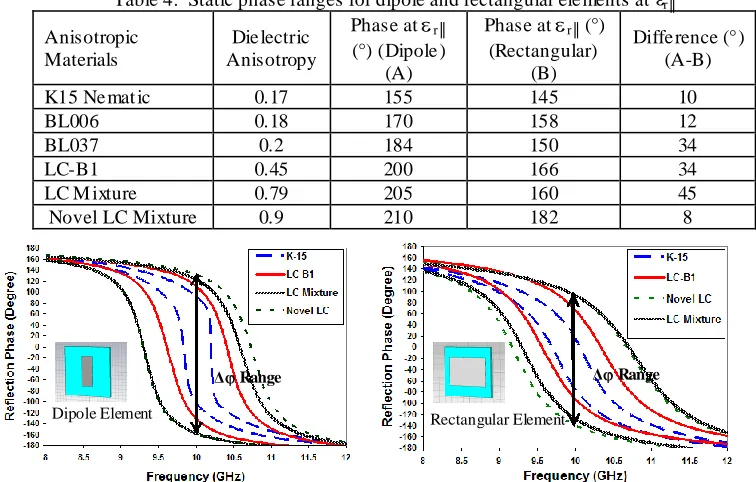
Fig. 2. Re flect ion phase curves and dynamic phase ranges of dipole and rectangular ele ments
[image:4.596.112.490.138.379.2]Fig. 2 shows the dynamic phase ranges for dipole and rectangular patches printed on different anisotropic liquid crystal materials. Table 5 contains the values of dynamic phase ranges for both dipole and rectangular elements, which shows that novel LC mixture offers maximum dynamic phase ranges of 290° and 230° for dipole and rectangular elements respectively. By noticing Fig. 2 and Table 5 it has been observed that dipole element attains wider dynamic phase ranges as compared to rectangular element. This is because the patch elements having less reflecting area contribute steeper phases as compared to those, having larger reflecting area as discussed in [7] and [9], for that reason dipole element is feasible to use for the systems where wider phase angles are required for scanning purposes and rectangular element is feasible to apply for the systems where larger frequency tunability is required.
Table 5. Dyna mic phase ranges for dipole and rectangular e le ments
Anisotropic materia ls
Die lectric anisotropy
Dynamic Phase Range(°) (Dipole )
(A)
Dynamic Phase Range(°) (Rectangular) (B)
Diffe rence (°) (A-B)
K15 Ne mat ic 0.17 195 90 105
BL006 0.18 167 85 82
BL037 0.2 160 90 70
LC-B1 0.45 240 160 80
LC M ixture 0.79 280 222 58
Novel LC
Mixture 0.9 290 230 60
Dipole Element
Dipole Element Rectangular Element
[image:4.596.122.498.584.708.2]International Seminar on the Application of Science & Mathematics 2011 ISASM 2011
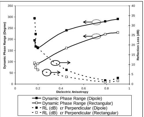
3.3 Behavior of Dynamic Phase Range and Reflection Loss over Dielectric Anisotropy
[image:5.596.187.437.307.510.2]The summary of the relationship between dynamic phase change and reflection loss over dielectric anisotropy is shown in Fig. 3. As depicted in Fig. 3 demonstrates that as dielectric anisotropy increases from 0.17 to 0.9 the dynamic phase range also increases from 195° to 290° and 85° to 230° for dipole and rectangular elements respectively. Where as when dielectric anisotropy increases from 0.17 to 0.79 the reflection loss decreases from 33.51 to 1.8 dB and 10.74 to 0.89 dB for dipole and rectangular elements respectively. Further more it is clear from Fig. 3 that low loss anisotropic materials offer wider dynamic phase ranges compared to high loss materials which offer narrower dynamic phase ranges.
Fig. 3. Effect of die lectric anisotropy over dynamic phase range and reflection loss
4. CONCLUSION
The results obtained from Finite Integral Method analysis, demonstrate that the losses in the dielectric substrate of the reflectarray can be optimized by the selection of a proper dielectric material. A suitably selected material can also increase the phase range performance of reflectarray that is required to realize a progressive phase distribution. Further more different types of resonating patch elements such as dipole and rectangular can also enhance the performance of reflectarray antenna in terms of lower reflection losses and wider dynamic phase ranges. Dielectric anisotropic materials are shown to offer rapid dynamic phase change behavior for designing a tunable reflectarray antenna particularly for satellite and radar systems. Moreover it has also been shown that different material properties including dielectric anisotropy along
0 50 100 150 200 250 300 350
0 0.2 0.4 0.6 0.8 1
Dielectric Anisotropy D y n a m ic P h a s e R a n g e ( D e g re e ) 0 5 10 15 20 25 30 35 40 R e fl e c ti o n L o s s ( d B )
Acknowledgments
This project is sponsored by Fundamenta l Research Grant Scheme (FRGS VOT 0718) of Ministry of Higher Education of Malaysia. We would like to thank the staff of Radio Communications and Antenna Design (RACAD) laboratory of University Tun Hussein Onn Malaysia (UTHM) for the technical support.
References
[1] Huang, J. and J. Encinar (2007) Reflect Array Antennas Wiley Inter Science,
USA, ISBN:9780470084915, pp: 1-5.
[2] R.D. Javor, X.-D. Wu and IC. Chang (1994). Dual polarisation of microstrip
reflectarray antenna ELECTRONICS LE77ERS Vol. 30 No. 1,pp.1018-1019.
[3] Huang, J. Analysis of microstrip reflectarray antenna for micro spacecraft
applications Spacecraft Telecommunications Equipment Section, TDA Progress
Report, pp: 42-120.
[4] M. Y. Ismail, M. Inam and A. M. A. Zaidi (2010). Reflectivity of Reflectarrays
based on dielectric substrates American J. of Engineering and applied Sciences 3 (1): ISSN 1941-7020, 2010, pp. 180-185.
[5] Saygin Bildik, Carsten Fritzsch, Alexander Moessinger, Rolf Jakoby (2010)
Tunable Liquid Crystal Reflectarray with Rectangular Elements 978-3-9812-6681-8 (c) IMA, German Microwave Conference.
[6] A. Gaebler, F. Goelden, A. Manabe, M. Goebel, S. Mueller, R. Jakoby.
Investigation of High Performance Transmission Line Phase Shifters Based on Liquid Crystal Proceedings of the 39th European Microwave Conference, pp.594-597.
[7] M.Y. Ismailand M. F. M. Shukri. Study of phasing distribution characteristics of
reflectarray antenna using different resonating elements, International Journal of Integrated Engineering (Issue on Electrical and Electronic Engineering), pp.47-52.
[8] M.Y. Ismail and R. Cahill (2005). Beam Steering Reflectarrays Using Liquid Crystal Substrate Tenth IEEE High Frequency Postgraduate Student Colloquium, University of Leeds, pp. 62-65.
[9] D.M. Pozar and T.A. Metzler (1993). Analysis of a reflectarray antenna using