A CFD Analysis of Rectangular Winglet Vortex
Generators in Heat Exchanger
Miftakh F. Hanifan, Gunawan Nugroho
*, Ridho Hantoro, Sarwono
Department of Engineering Physics, Sepuluh Nopember Institute of Technology, Indonesia
Copyright©2017 by authors, all rights reserved. Authors agree that this article remains permanently open access under the terms of the Creative Commons Attribution License 4.0 International License
Abstract
A good performance of the heat exchanger will support energy efficiency and economic sustainability. One way to improve heat transfer coefficient is to increase turbulent flow by using vortex generators. The addition of vortex generators on heat exchanger will pose wake on the flow field which then reduce the stability of thermal boundary layer and enhance heat transfer coefficient. The effect of winglet vortex generators with the variations of angle of attack (AoA) is studied in this research. Each variation is applied in a single row and three rows of inline configurations. The results show that the addition of vortex generators with 1600 angle of attack and three rows of inlineconfiguration improve heat transfer coefficient as 59% higher than conventional configurations.
Keywords
Heat Exchanger, Vortex Generators, Heat Transfer Coefficient, Computational Fluid Dynamics1. Introduction
Heat exchanger is a kind of important equipment and commonly applied in HVAC systems, power plants, waste heat utilization systems, and chemical processing systems [1]. One way to improve heat transfer coefficient on the air side is to increase the flow turbulence by using vortex generators. The addition of vortex generators into heat exchanger will cause longitudinal vertices in the flow field. The longitudinal vertex will decrease the stability of the thermal boundary layer and increase convection coefficient [2].
Research on the application of vortex generator as a heat transfer enhancement mechanism was conducted with attention to the location of placement, shape and its orientation. Research was performed by comparing the arrangement of inline and staggered heat exchanger tubes. Based on the research, it was found that there was an increase of 30% Nusselt number in the inline tube arrangement and 5.5% in the staggered tube arrangement [3]. According to the latest research, vortex generator with inline tube arrangement
is more optimal for increasing heat transfer. In addition, the shape of the vortex generators is also discussed. The study of vector-shaped paired winglet generators was shown to improve the heat transfer process in heat exchangers [4,5]. Meanwhile, Tian et al. studied and compared the performance between delta shaped vortex generators and rectangular winglet at Reynolds number up to 1200. The results show that rectangular winglets are better for increasing heat transfer compared to delta winglet pairs. Moreover, the arrangement of vortex generator also affects the heat transfer process. The three rows inline arrangement of vortex generators increased heat transfer up to 68% while single row of inline arrangement is only 44% [6]. The angle of attack also affects heat transfer process for the case of 1600,
1650, and 1700. The 1600 degree is the best for improving the
fluid heat transfer coefficient around the tubes as observed by A. Sinha et al. [2].
Based on the previous research, numerical simulation is necessary for the application of vortex generators in heat exchanger with variation of AoA and their arrangement. In this work, the variation of winglet AoA and their configurations are performed to produce more turbulence and higher heat transfer coefficient.
2. Research Methodology
2.1. Geometrical Parameter
In this research, the design geometry from experimental research conducted by Joardar and Jacobi is applied [6]. It has the inline tube arrangement. The stream domain is 177.8mm×101.6mm size. The tube diameter is 10.6mm with a thickness of 0.375mm. As for the vortex generator, the rectangular winglet type is implemented and the geometry and placement are illustrated in the following figure.
In Figure 1, the winglet angle of attack is 1650 which will
be varied in 1700, 1650 and 1650. The single-row and
numerical simulation as in A. Sinha et al.’s study [2].
Figure 1. Winglets arrangement [6]
Figure 2. The arrangements of vortex generators (a) single row (b) three rows [6]
2.2. Simulation
2.2.1. Pre-processing
[image:2.595.80.277.119.345.2] [image:2.595.67.282.121.576.2]The pre-processing stage consists of geometric design, meshing, determination of boundary conditions and fluid properties. The applied geometric design is based on the specified reference which one example is depicted as follows:
[image:2.595.63.286.362.582.2]Figure 3. The geometric design
Figure 3 shows the variations of vortex generators in three rows arrangement with 1600 angle of attack. Inline
arrangement for 28 tubes is also implemented. The number of vortex generators is 24 three rows configuration, while 8 for single configuration.
The next step is creating small elements which, each element calculates various mathematical equations such as mass conservation, energy, and momentum. On each side of the tube and vortex generators, the edge sizing of 0.001 mm is applied. The results are tabulated as following:
Table 1. Meshing
Arrangement Angle of Attack Nodes Elements Maximum Skewness
Without Vortex Generator 509720 939959 0.88
Single row
1600 543404 1002751 0.81
1650 744808 1378970 0.94
1700 648968 1198599 0.92
Three rows
1600 779679 1440812 0.92
1650 984473 1823803 0.93
1700 904709 1673688 0.94
2.2.2. Processing
[image:2.595.312.550.525.666.2]Table 2. Boundary Conditions
Boundary Condition Details
Inlet
Type Velocity Inlet
Air Velocity 3.2m/s
Temperature 300K
Tube Wall Type Stationary Wall
Temperature 330K
Outlet Type Outflow
As for the material properties, the conditions are:
Table 3. Material Properties
Properties Value
Density 2719 kg/m3
Specific Heat 871 J/kg K
Thermal Conductivity 202.4 W/m K
Then, the air inlet conditions are listed as:
Table 4. Inlet air properties
Properties Value
Temperature 300K
Density 1.1614 kg/m3
Specific Heat 1007 J/kg K
Kinematic Viscosity 15.89E-06
Thermal Conductivity 0.0263 W/m K
Prandtl 0.707
2.2.3. Post-processing
Furthermore, the standard K-epsilon is implemented in this work. This is due to its accuracy in the fluid flow calculations involving swirling flow, large pressure gradient, separation, and recirculation.
3. Results and Discussion
3.1. Validation
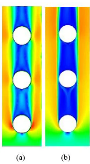
The result of velocity distribution is compared with the obtained data from Sinha [2] as shown in figure 4. In his study, the velocity distribution was simulated with inline tube arrangements without using vortex generators. It is shown the fluid flow similarity, which in the early rows a small blue region at tube end shows the point of stagnation. At this point, the fluid velocity is close to zero and the pressure increases. The area of flow separation is observed downstream. In overall, these two geometries have similarities in fluid phenomena around the tubes which validate the simulation.
Figure 4. The comparison of velocity distribution
3.2. Influence of Single Row and Three rows Configurations on Velocity Distribution
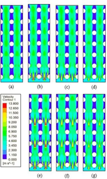
In this simulation, the inlet air velocity is 3.2 m/s in the direction of the positive y axis. Figure 5 depicts the increase air velocity at each gap between the vortex generators. The velocity increase is due to the area contraction through a small cross section. It is also observed that higher angle of attack decreases velocity between the gaps due to the widening of cross-sectional area between vortex generators. Figure 5(a) shows that the air velocity tends to increase with the addition of tube rows, whereas geometric design using vortex generators of figures 5(b) (c) (d) (e) (f) (g) illustrate the velocity increase from the initial row due to an increase of turbulence.
[image:3.595.358.505.76.343.2]Figure 5. Influence of single row and three rows configurations on Velocity Distribution (a) Without VG (b) Single row 1600 (c) Single row 1650 (d) Single row 1700 (e) Three rows 1600 (f) Three rows 1650 (g) Three rows 1700
3.3. Analysis of Single Row and Three Rows Configurations on Reynolds Number
[image:4.595.87.262.79.369.2]The calculation of Reynolds Numbers using the variable maximum velocity is listed in Table 5. It appears that there is a slight increase in Reynolds number by 110% from the design without vortex generators. It is seen that the highest flow turbulence is in the three rows configuration. This is because the flow turbulence in the three rows arrangement is always re-raised on each line. While the single row turbulence flow is only manipulated on the first line only. Meanwhile, Reynolds number decreases with respect to angle of attack. Higher angle of attack extends the cross-sectional area passed by the fluid flow, and generates smaller velocity and then, Reynolds number.
Table 5. The Influence of Single Row and Three Rows Configurations on Reynolds Number
Arrangement Angle of Attack Reynolds Number
Without VG 4451.99
Single row
1600 9598.30
1650 7718.79
1700 6533.61
Three rows
1600 9617.77
1650 7890.03
1700 7505.93
Table 5 shows that the value of the highest Reynolds number is in the variation of three rows arrangement with 1600 angle of attack. It is found that large flow turbulence is
related to the angle of attack which produces small cross-sectional area. However, this value is only 0.2% higher than the Reynolds number from a single row arrangement with 1600 angle of attack, which is an indicator of small
velocity difference between two configurations, respectively.
3.4. The Influence of Single Row and Three Rows Configurations on Nusselt Number
[image:4.595.311.553.319.442.2]Nusselt number is regarded as the ratio of convection to conduction heat transfer, which plays a fundamental role for the thermal performance. In this case, table 6 illustrates heat transfer performance with respect to angle of attack and row configurations.
Table 6. The influence of AoA and row configurations on Nusselt Number
Arrangement Angle of Attack Nusselt Number
Without VG 44.96
Single row
1600 72.95
1650 63.59
1700 57.25
Three rows
1600 73.04
1650 64.47
1700 62.48
It is observed that the vortex generator increases Nusselt numbers up to 59% compared to geometric designs without vortex generators. This is similar to Reynolds number which increases in the design using vortex generators. Higher Nusselt number is inversely proportional to the angle of attack and the results are consistent with the explanation that velocity and turbulence is smaller with higher angle of attack. Moreover, the increase in Nusselt number for the three rows configuration is higher than a single row. However, the two arrangements only differed by 0.12% in overall because the velocity is almost the same.
3.5. Analysis of the Influence of Single Row and Three rows of Vortex Generators on Temperature Distribution
[image:4.595.58.299.633.742.2]9.88
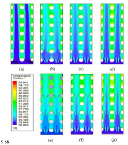
Figure 6. Analysis of the Influence of Single Row and Three rows of Vortex Generators on Temperature Distribution (a) Without VG (b) Single row 1600 (c) Single row 1650 (d) Single row 1700 (e) Three rows 1600 (f) Three rows 1650 (g) Three rows 1700
As described earlier, this research is based on the experiment conducted by Joardar et al. [2] which a comparison between a single row and three rows arrangement with fixed angle of attack was performed. The vortex generator managed to increase the airside convection coefficient by 68.8% for three rows configurations. Since this work produces 58% increase of convection coefficient, it is necessary for the future work to investigate this different value of whether the fluid flow phenomena is highly three-dimensional.
4. Conclusions
Research on a CFD analysis of vortex generator in the tube
arrangements is conducted. This work implements the variation of AoA and vortex generator in a single and three rows configurations. The results show that the addition of vortex generators increases the maximum velocity around the tubes due to the area contraction of small cross section. It is also observed that there is an increase of Nusselt number up to 59% compared with those that do not apply vortex generators. The highest Nusselt number is on the 1600 angle
of attack. Moreover, Nusselt number on the three rows configuration is 0.12% higher than a single row as well as more distributed temperature is achieved.
REFERENCES
[1] F.P. Incropera, D.P. Dewitt, T.L. Bergman, A.S. Lavine, Fundamentals of Heat and Mass Transfer 7th Edition, John Wiley & Sons, 2011, USA.
[2] A. Sinha, H. Chattopadhyay, A. Kannan, G. Biswas, Enhancement of Heat Transfer in a Fin-Tube Heat Exchanger Using Rectangular Winglet Type Vortex Generators, International Journal of Heat and Mass Transfer, Vol. 101, 2016, pp. 667–681.
[3] A. Valencia, N.K. Mitra, Wing-Type Vortex Generators for Fin-and-Tube Heat Exchangers, Experimental Thermal and Fluid Science, Vol. 7, Issue 4, 1993, pp. 287–295.
[4] A.M. Jacobi, R.K. Shah, Heat Transfer Surface Enhancement through the Use of Longitudinal Vortices : A Review of Recent Progress, Experimental Thermal and Fluid Science, Vol. 11, Issue 3, 1995, pp. 295–309.
[5] L. Tian, Y. He, Y. Lei, W. Tao, Numerical Study of Fluid Flow and Heat Transfer in a Flat-Plate Channel with Longitudinal Vortex Generators by Applying Field Synergy Principle Analysis, Int. Commun. Heat Mass Transf., Vol. 36, No. 2, 2009, pp. 111–120.
[image:5.595.70.283.77.318.2]![Figure 1. Winglets arrangement [6]](https://thumb-us.123doks.com/thumbv2/123dok_us/8790895.909211/2.595.63.286.362.582/figure-winglets-arrangement.webp)