2898
A MODIFIED BIT PLANE COMPLEXITY SEGMENTATION
STEGANOGRAPHIC METHOD: INCREASING PAYLOAD
IMPERCEPTIBILITY AND ROBUSTNESS
GABRIEL KAMAU1*, WAWERU MWANGI2, WILSON CHERUIYOT3
1 School of Computer Science and Information Technology, Dedan Kimathi University of Technology,
Nyeri Kenya
2, 3 School of Computer Science and Information Technology, Jomo Kenyatta University of Agriculture and
Technology, Nairobi, Kenya E-mail: [email protected]
ABSTRACT
Embedding of secret information in a digital image will definitely introduce some noise or modulate the image signal in some way. A good steganographic method ensures that such noise is not perceptible or is minimal in order to maintain the fidelity of the vessel. The Bit Plane Complexity Segmentation (BPCS) method uses the Canonical Gray Coded (CGC) bits of the complex bit plane blocks of a vessel image for embedding secret information. Though this guarantees a high payload capacity, it can potentially compromise the fidelity of the vessel particularly in its high order bits. To ensure that the vessel is evenly modulated and hence increase imperceptibility of the embedded data, this paper suggests a tweaking of the BPCS embedding procedure by employing a random selection of the CGC bits in the noisy regions of the vessel. Additionally, in order to boost the vessel’s robustness against compression and other image processing activities, the proposed embedding procedure does not utilize the 0 (zero) CGC bit plane, which is normally targeted for removal by such activities. Results from the experiments carried out showed that stego images from the proposed method had improved signal to noise ratios compared to those from the traditional BPCS method.
Keywords: Steganography, fidelity, floor noise, payload, compression, embedding rate
1. INTRODUCTION
All steganographic algorithms must comply with basic requirements for steganography. The most important of this requirement is that the embedding procedure must not leave perceptible distortions in the carrier vessel. This ensures that the fidelity of the carrier file is not compromised and that the stego image’s statistical characteristics are consistent with those of the original image [1]. The second requirement is to ensure that the embedding procedure provide for adequate payload capacity. This is the size of information that can be embedded relative to the size of the cover file without degrading it [2]. A good steganographic algorithm should therefore ensure a high payload capacity without perceptibly degrading the carrier vessel. Lastly, the secret information should be embedded robustly to guard against effects of vessel manipulation on the embedded data.
Robustness ensures that a carrier vessel can withstand some level of modification without necessarily affecting the integrity of the hidden information [3].
2899 mutually competitive nature of these parameters [2].
Figure 1:The Data-hiding problem space
2. THE BPCS METHOD
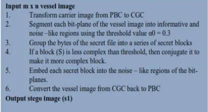
BPCS embedding technique was firstly introduced by Kawaguchi and Eason [6] as a solution to the low payload capacity of the traditional steganographic methods. In this method, the bits of the carrier vessel are first converted from the Pure Binary Code (PBC) to the CGC. Embedding secret data using the CGC bits pattern leaves less distortion to the original image bit map hence improving on the imperceptibility of the vessel [7]. The image is then subdivided into several bit planes, which are categorized as either “informative” or “noisy”. Noisy bit planes have high complexity. A threshold value α0 = 0.3 is used to determine the complexity of a bit plane by measuring how many times the bit of an image plane changes from 0 to 1 and from 1 to 0 [8]. If the complexity of any given bit plane exceeds the threshold, it is skipped during the embedding process. The complexity of the secret data to be embedded is also calculated and if found to be below the threshold value, it is conjugated to make it complex before it is embedded in the carrier file [9]. For a 2n x 2m gray scale black and white image
with black as the foreground area and white as the background area, conjugation operation proceeds as follows:
i) Two checkboard patterns Wc and Bc are
introduced where Wc has white pixel (i.e 1) at the upper left position and Bc has a black pixel (i.e 0) upper left position.
ii) Image P is introduced which has its pixels in foreground area with B(black) pattern, and its pixels in the background area with W(White pixels).
Figure 2:Conjugation binary patterns
iii) P* is then defined as the conjugate of P satisfying the following conditions:
a) The foreground area shape is the same as P b) The foreground area has the Bc pattern c) The background area has the Wc pattern
The following properties hold true for the conjugation operation. [9]
a) P* = P ō Wc where 0 designates exclusive OR b) P* ≠ P
c) If α (P) is the complexity of a given image P, then,
α(P*) = 1-α(P). (1)
[image:2.612.313.521.575.687.2]Since the Human Visual System (HVS) is more sensitive to patterns represented by the informative regions of the image, embedding of secret data is done in the noisy bit plane blocks in order to effectively conceal the information [5]. The method utilizes both the Most Significant Bits (MSB) and the Least Significant Bits (LSB) of the noisy blocks of the vessel ensuring a significantly high embedding rate compared to the traditional LSB methods which utilize only the LSBs of the vessel. The BPCS embedding procedure is summarized in figure 3.
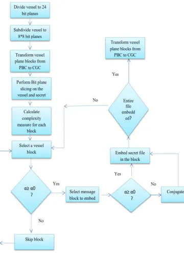
2900 One of the advantages of the BPCS embedding technique is its high payload capacity. However due to the data hiding problem space, increased payload in a vessel imparts negatively on imperceptibility. Additionally, robustness of the carrier vessel against image processing activities such as compression is key to ensuring that the embedded information is safe. BPCS is not robust to even small changes in the image unless the secret data is embedded in high order bit planes which would consistently compromise on the imperceptibility of the vessel [6]. The BPCS embedding framework is shown in figure 4.
Figure 4: BPCS embedding framework
3. THE PROPOSED METHOD
To increase imperceptibility and robustness in the traditional BPCS method, this paper proposes a modification to its embedding procedure by tweaking it using the Marsenne Twister (MT) Pseudo Random Number Generator (PRNG), in order to randomly scatter the bits of the secret data in the CGC bits of the carrier vessel. MT provides for fast generation of very high-quality pseudorandom numbers with a long period length which is chosen to be a mersenne prime [10]. Using the PRNG to spread the bits of the secret data within the bit planes of the vessel not
only ensures that the modulation of the carrier vessel is uniformly done, but also that the extraction of the embedded data and the eventual reconstruction of the embedded file is impossible without the original seed used in generating the pseudo random numbers [11]. This further increases the security of the embedded data.
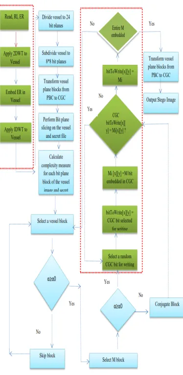
[image:3.612.131.311.254.501.2]To improve on the robustness of the stego system, the 0 bit plane of the noisy region of the vessel is skipped during the embedding process as it is normally targeted for removal by lossy compression algorithms. The summary of the proposed embedding and extraction procedures are shown in figure 5 and figure 6 respectively. The complete proposed MBPCS framework is shown in figure 7. The highlighted areas indicate the proposed modifications.
[image:3.612.310.520.318.587.2]2901
[image:4.612.92.279.327.709.2]Figure 6: Proposed MBPCS extraction procedure
Figure 7: Proposed MBPC framework
4. EXPERIMENT RESULTS AND PERFORMANCE EVALUATION
An experiment was set up to compare the results of the proposed method with those of the traditional BPCS method. The quality of the stego images produced by each method was evaluated through an objective quantitative criterion where the metric ϴ (x,y) was used to estimate the difference between a stego image and the original reference vessel image. Twenty randomly sampled payload images were used in this experiment. These were embedded in five standard steganographic test images as vessels (i.e Lenna.png, Boat.png, House.bmp, Peppers.png and Fruits.png). The results were then analyzed using full reference image error sensitivity analysis metrics [12]. The tests assume that the original perfect vessel image is available for comparison with the stego image [13]. The experiment ensured the following constants.
i) Same steganography test images were used on both the methods.
ii) Equal payload images were embedded in each vessel.
iii) Same quality evaluation metrics were measured and recorded.
iv) All the tests were implemented and run on a PC pentium IV Duo core, 2.1 GHz with 2GB of RAM Under the Windows 7 Home Edition operating system.
2902
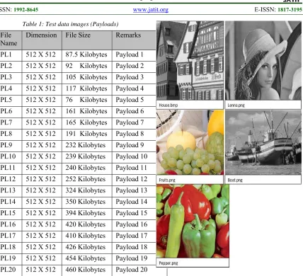
Table 1: Test data images (Payloads)
File
[image:5.612.93.524.70.460.2]Name Dimension File Size Remarks PL1 512 X 512 87.5 Kilobytes Payload 1 PL2 512 X 512 92 Kilobytes Payload 2 PL3 512 X 512 105 Kilobytes Payload 3 PL4 512 X 512 117 Kilobytes Payload 4 PL5 512 X 512 76 Kilobytes Payload 5 PL6 512 X 512 161 Kilobytes Payload 6 PL7 512 X 512 165 Kilobytes Payload 7 PL8 512 X 512 191 Kilobytes Payload 8 PL9 512 X 512 232 Kilobytes Payload 9 PL10 512 X 512 239 Kilobytes Payload 10 PL11 512 X 512 240 Kilobytes Payload 11 PL12 512 X 512 252 Kilobytes Payload 12 PL13 512 X 512 324 Kilobytes Payload 13 PL14 512 X 512 350 Kilobytes Payload 14 PL15 512 X 512 394 Kilobytes Payload 15 PL16 512 X 512 420 Kilobytes Payload 16 PL17 512 X 512 410 Kilobytes Payload 17 PL18 512 X 512 426 Kilobytes Payload 18 PL19 512 X 512 454 Kilobytes Payload 19 PL20 512 X 512 460 Kilobytes Payload 20
Table 2: Test data (Vessels)
File Name Dimensi ons
File Size Remark s Lenna.png 512 x
512 117 Kilobytes Vessel 1 Boat.png 512 x
512 174 Kilobytes Vessel 2 House.bmp 512 x
512
258 Kilobytes
Vessel 3
Peppers.png 512 x 512
527 Kilobytes
Vessel 4
Fruits.png 512 x 512
426 Kilobytes
Vessel 5
Figure 8 shows the vessel images used as test data for this experiment.
Figure 8: Test data (vessel images)
4.1 Evaluation Metrics
The Mean Square Error (MSE) and the Peak Signal to Noise Ratio (PSNR) full reference metrics were used to compare the quality of the stego image signals produced by each method under equal payloads.
4.1.1 The MSE
MSE measures the average pixel intensity difference between two images, in this case the original and the stego image [14]. MSE is calculated using equation 1. Lower levels of MSE indicate a better quality image signal [12].
2
1 1
1
M NAVG ij ij
i J
MSE
X
X
MN
(2)
Where:
ij
[image:5.612.85.284.512.642.2]2903 in the original vessel image,
ij
X
is the ith row and the jth column pixelin the stego image,
M and N are the height and the width of the image. Table 3 shows a comparison of MSE bench mark test results for the traditional BPCS method and the proposed Modified Bit Plane Complexity Segmentation (MBPCS) technique using vessel 1 (lenna.png) with payloads 1 to 4. These results are further summarized in figure 9.
Table 3: MSE for Vessel 1
Embedding Technique
Payload 1
Payload 2
Payload 3
Payload 4 BPCS
method
12.10 11.91 10.77 11.10
MBPCS method
3.0 2.93 2.77 2.78
Figure 9: MSE for vessel 1
Table 4 shows a comparison of MSE bench mark test results for the traditional BPCS method and the proposed MBPCS technique using vessel 2 (boat.png) with payloads 5 to 8. These results are further summarized in figure 10.
Table 4: MSE for vessel 2
Embedding
Technique Payload 5 Payload 6 Payload 7 Payload 8 BPCS
method
13.55 13.58 13.60 13.62
MBPCS
method 4.51 4.60 4.57 4.53
Figure 10: MSE for vessel 2
Table 5 shows a comparison of MSE bench mark test results for the traditional BPCS method and the proposed MBPCS technique using vessel 3 (house.bmp) with payloads 9 to 12. These results are further summarized in figure 11.
Table 5: MSE for vessel 3
Embedding
Technique Payload 9 Payload 10 Payload 11 Payload 12 BPCS
method
13.12 12.96 12.87 13.07
MBPCS method
4.17 4.15 4.18 4.15
Figure 11: MSE for vessel 3
Table 6 shows a comparison of MSE bench mark test results for the traditional BPCS method and the proposed MBPCS technique using vessel 4 (peppers.png) with payloads 13 to 16. These results are further summarized in figure 12.
Table 6: MSE for vessel 4
Embedding Technique
Payload 13
Payload 14
Payload 15
Payload 16 BPCS
method
11.88 11.65 11.85 11.86
MBPCS method
2904
Figure 12: MSE for vessel 4
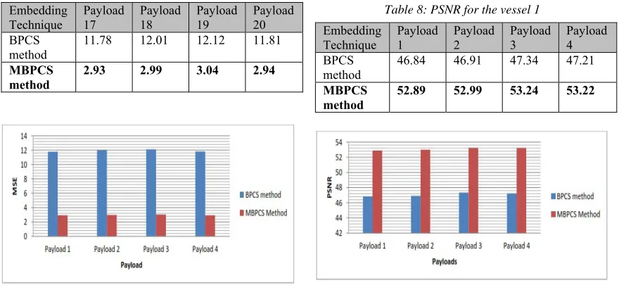
Table 7 shows a comparison of MSE bench mark test results for the traditional BPCS method and the proposed MBPCS technique using vessel 5 (fruits.png) with payloads 17 to 20. These results are further summarized in figure 13.
Table 7: MSE for the vessel 5
Embedding
Technique Payload 17 Payload 18 Payload 19 Payload 20 BPCS
method 11.78 12.01 12.12 11.81 MBPCS
method 2.93 2.99 3.04 2.94
Figure 13: MSE for vessel 5
The proposed MBPCS posted lower levels of MSE metrics in all the vessels for all the payloads considered. It was also noted that increase in payload resulted in minimal changes in MSE metrics for the proposed method compared to the traditional BPCS. Since MSE is the squared euclidean norm of the pixel-wise difference between the reconstructed and the original image, the proposed embedding algorithm ensures minimal and equitable pixel differences in the stego files.
4.1.2 The PSNR
PSNR is used for comparing the value of the required image signal against the value of a corrupting noise in decibels [15]. The lesser the value of PSNR, the more perceptible the background noise [16]. The value of PSNR is computed using equation 2.
2
10.log10
I
PSNR
db
MSE
(3)
Where:
I is the dynamic range of pixel values I=255
for 8-bit images.
MSE is the Mean Square Error.
[image:7.612.89.529.347.553.2]Table 8 shows a comparison of PSNR bench mark test results for the traditional BPCS method and the proposed MBPCS technique using vessel 1 (lenna.png) with payloads 1 to 4. These results are further summarized in figure 14.
Table 8: PSNR for the vessel 1
Embedding Technique
Payload 1
Payload 2
Payload 3
Payload 4 BPCS
method
46.84 46.91 47.34 47.21
MBPCS method
52.89 52.99 53.24 53.22
Figure 14: PSNR for vessel 1
Table 9 shows a comparison of PSNR bench mark test results for the traditional BPCS method and the proposed MBPCS technique using vessel 2 (boat.png) with payloads 5 to 8. These results are further summarized in figure 15.
Table 9: PSNR for the vessel 2
Embedding
Technique Payload 5 Payload 6 Payload 7 Payload 8 BPCS
method
46.35 46.34 46.33 46.32
MBPCS method
2905
Figure 15: PSNR for vessel 2
Table 10 shows a comparison of PSNR bench mark test results for the traditional BPCS method and the proposed MBPCS technique using vessel 3 (house.png) with payloads 9 to 12. These results are further summarized in figure 16.
Table 10: PSNR for the vessel 3
Embedding Technique
Payload 9
Payload 10
Payload 11
Payload 12 BPCS
method 46.49 46.54 46.57 46.50 MBPCS
method
51.46 51.48 51.45 51.48
Figure 16: PSNR for vessel 3
Table 11 shows a comparison of PSNR bench mark test results for the traditional BPCS method and the proposed MBPCS technique using vessel 4 (peppers.png) with payloads 13 to 16. These results are further summarized in figure 17.
Table 11: PSNR for the vessel 4
Embedding
Technique Payload 13 Payload 14 Payload 15 Payload 16 BPCS
method 45.80 45.89 45.82 45.81 MBPCS
method 51.84 51.90 51.84 51.83
Figure 17: PSNR for vessel 4
Table 12 shows a comparison of PSNR bench mark test results for the traditional BPCS method and the proposed MBPCS technique using vessel 5 (fruits.png) with payloads 17 to 20. These results are further summarized in figure 18.
Table 12: PSNR for the vessel 5
Embedding Technique
Payload 17
Payload 18
Payload 19
Payload 20 BPCS
method
46.95 46.87 46.83 46.94
MBPCS method
52.99 52.91 52.83 52.98
Figure 18: PSNR for vessel 5
2906
5. RESEARCH CONTRIBUTION
The study and the findings established in this research contributes to the theory and the practical application of information hiding techniques by tackling the data hiding problem space in stego systems thereby improving the embedding capacity and robustness of a carrier vessel.A steganographic artifact that provides a high payload capacity, while ensuring that the vessel is robust against compression and filtering consequently represents a contribution in this area. Based on the results presented and discussed in this paper, the proposed MBPCS method clearly provides an improved high hiding capacity while ensuring that the fidelity and quality of the carrier file remains fairly uncompromised. This is in comparison to existing LSB techniques and the original BPCS method. Therefore the proposed embedding method therefore presents an acceptable trade-off between high payload capacity and the stego image robustness reducing the data hiding problem space.
Data imperceptibility is at the core of any usable steganographic method. While embedding information in a digital image is definitely expected to introduce noise or modulate the cover image in some way [17], the important thing is to ensure that the introduced noise does not degrade the perceived quality of stego image in order to maintain the security of the steganographic system. In this paper, an embedding technique that utilizes the marsenne twister PRNG to randomly and uniformly scatter the information within the CGC bits of vessel’s bit planes forms a significant contribution compared to the techniques used in the traditional LSB and BPCS methods. This is demonstrated by the MSE and PSNR results presented. Increased imperceptibility of the embedded information in a carrier file helps to ensure the security of the entire steganographic sytem. A good steganographic method therefore ensures that the embedding procedure introduces minimal noise to the carrier vessel in order to ensure that the statistical characteristics of both the original vessel and the stego image are almost indistinguishable [18].
6. CONCLUSION
Imperceptibility of the embedded information is at the core of any usable steganographic method. While embedding information in a digital image is definitely expected to modulate the cover image in some way [14], the important thing is to ensure that the introduced noise does not perceptibly degrade the vessel in
order to guarantee the security of the embedded data.
In this paper, an embedding technique that utilizes the MT to randomly and uniformly scatter the information within the CGC bits of the vessel’s noise like bit planes was proposed and evaluated. MSE and PSNR results demonstrated improvements on the quality of stego images produced by the proposed technique. In any steganographic method, imperceptibility of the hidden data cannot be compromised and a good steganographic method should ensure that the embedding procedure introduces minimal noise to the carrier vessel [14].
7. RECOMMENDATION AND FUTURE WORK
The steganographic method presented in this research was found to be significantly effective as it makes minimal imperceptible modifications to the cover images. In comparison to existing traditional LSB methods, the proposed MBPCS method posted relatively superior results in most of the bench mark tests in steganography. As is the practice in digital image steganography, the recommended carrier images should be original photographs taken from high quality digital cameras. The recommended mode of transmission of the stego images is through web postings, email attachments, electronic bulletin boards and by file transfer such as file transfer protocol (FTP) (Cole,2013). Whichever method of transmission is chosen, it should be one that prevents tracing by potential attackers.
To further strengthen the proposed method, other carrier files and stego media such as audio, video and text can be tested for this application to establish their versatility in terms of data hiding problem space and security.
ACKNOLEDGEMENTS
We thank in advance the effort of the reviewers and the editors.
COMPETING INTERESTS
2907
REFERENCES
[1] C. Cachin, (1998).``An information-theoretic model for steganography,'' in Information Hiding. Berlin, Germany: Springer, 1998, pp. 306-318.
[2] J. Fridrich and J. Kodovský, (2012).``Rich models for steganalysis of digital images,'' IEEE Trans. Inf. Forensics Security, vol. 7, no. 3, pp. 868-882.
[3] Kethepalli Mallikarjuna, Kodati Satya Prasad and Makam Venkata Subramanyam. (2016).” Image Compression and Reconstruction using Discrete Rajan Transform Based Spectral Sparsing”. Image, Graphics and Signal Processing, 1, 59-67
[4] V. Sedighi, R. Cogranne, and J. Fridrich,(2016). “Content-adaptive steganographyby minimizing statistical detectability,” IEEE Transactions on Information Forensics and Security, vol. 11, no. 2, pp. 221–234.
[5] Geomi A.G. & Prabavathy, A.K (2014). A Survey On Different Approaches Used In Image Quality Assessment. International Journal of Emerging Technology and Advanced Engineering pp 197-203
[6] Kawaguchi E. & Eason R.,(1998). Principles and Applications of BPCS-steganography. Kyushu Institute of technology, Kitakyushu, Japan University of Maine, Orono, Maine 04469-5708.
[7] Andysah Putera & Utama Siahaan, (2016). High Complexity Bit-plane BPCS steganography. Intenational Journal of Computer Applications, 148(3): 17-22
[8] Makoto Matsumoto and Y. Kurita, (1992).“Twisted GFSR generators” ACM Trans. On Modeling and
Computer Simulation, vol. 2, pp. 179-194 [9] Lahane, P., Kumbhar, Y., Patil, S., More, S., &
Barse, M. (2015). Visual Cryptography and BPCS Steganography for Data Shielding. International Journal Of Engineering And Computer Science. Vol4 11997
[10] Makoto Matsumoto & Takuji Nishimura (1997). Mersenne twister: a 623-dimensionally equidistributed uniform pseudorandom number generator. ACM Trans. on Modeling and Computer Simulation, vol. 8, no. 1, pp. 3-30 [11] Betsy Samuel & Vidya N. (2015). Wavelet
Based Watermarking Approach of Hiding Patient Information in Medical Image for Medical Image Authentication. International Journal of Modern Trends in Engineering and Research. PP 453-458
[12] Y. Q. Shi, P. Sutthiwan, and L. Chen, (2013).“Textural features for steganalysis,” in Information Hiding. New York, NY, USA: Springer-Verlag, pp. 63–77.
[13] Kavitha, S. & Thyagharajan K. K,(2016). A Survey on Quantitative Metrics for Assessing the Quality of Fused Medical Images. Research Journal of Applied Sciences, Engineering and Technology 12(3): 282-293
[14] Wang,Z. & Li, Q.(2011). Information content weighting for perceptual image quality assessment. IEEE T. Image Process. 20(5): 1185-1198.
[15] Prabhishek,S. & Chadha, R.S. (2013). A Survey of Digital Watermarking Techniques, Applications and Attacks. International Journal of Engineering and Innovative Technology (IJEIT). pp 683-689
[16] Horé Alin & Ziou Djemel, (2010).International Conference on Pattern Recognition. IEEE DOI 10.1109/ICPR. Pp 2366-2369
[17] Venkatraman N., Reddy, L.S.S. & Kishore P.V.V.(2014). Blind Medical Image Watermarking with LWT – SVD for Telemedicine Application, WSEAS .Transactions on signal processing Vol(10),Issue 2.pp 656-669