ISSN: 1992-8645 www.jatit.org E-ISSN: 1817-3195
1398
INVESTIGATION ON BER SENSITIVITY TO DESIGN SNR
OF BHATTACHARRYA BOUNDS BASED CONSTRUCTION
OF POLAR CODES
1REDA BENKHOUYA, 2IDRISS CHANA, 3YOUSSEF HADI
1,3
MISC, Faculty of Sciences, Ibn Tofail University, Morocco 2
ISIC EST, LMMI ENSAM, Moulay Ismail University, Morocco
E-mail: [email protected], [email protected], [email protected]
ABSTRACT
Advanced coding has been widely used to accomplish the high-performance requirements of wireless communications. While adhering to the perspective on energy-spectral efficiency, channel coding is still promising. To deal with such challenge, research initiatives on the linear block error correcting codes have gained accelerating momentum. In this paper we introduce polar codes which have proven to meet the typical use cases of the next generation mobile standard. Such work is motivated by the suitability of polar codes for the coming wireless era. Hence, we investigate the performance of polar codes in terms of bit error rate (BER) for several codeword lengths and code rates. We first perform a discrete search to find the best design signal to noise ratio (SNR) at two different code rates, while varying the blocklength. We find in our extensive simulations that the BER becomes more sensitive to design SNR as long as we increase the blocklength and code rate. Finally, we note that increasing blocklength achieves an SNR gain, while increasing code rate changes the operational SNR domain. This trade-off sorted out must be taken into consideration while designing polar codes for high-throughput application.
Keywords: Polar Codes, Battacharrya Parameter, Successive Cancellation Decoding, Design SNR, BER
1. INTRODUCTION
With increase of high bandwidth wireless applications, more challenging channel coding schemes are required. Polar Coding scheme was proven to be capacity achieving for binary discrete memoryless channel (B-DMC). Combined with high order modulation, polar codes have been a powerful code candidate for the next generation mobile standard, where high transmission power efficiency and bandwidth efficiency are required [1]. Both polar encoding and decoding are of low complexity, which match green energy requirement [2]. Polar codes’ novelty enables their application in varying channels, which tackles the universal coverage requirement. On the other side, complex use scenarios result in heterogeneous networks where polar codes can find their suitable applications. Therefore, polar codes have become one popular topic and drawn intensive attentions from both academia and industry. Recent research progresses on polar codes can be mainly categorized into two trends: 1) advanced decoding algorithms for polar codes, and 2) efficient
hardware implementation methods for polar codes [2].
Polar codes are linear block codes that rely on a polarization phenomenon. The advent of polar codes is based on the channel polarization theory. The core idea of polar coding is to split a given vector channel into multiple correlated bit channels and to use only the good ones, in the sense that they are either extremely noisy or noiseless. Then, one can employ a separate sequential decoder on each subchannel. Polar codes have performed state-of-the-art codes of larger block lengths and code rates. Polar codes can also be used for source coding, but this use will not be discussed in this paper.
In the level of theoretical analysis and
development, substantial recent research progress has been achieved and reported. A by no means complete list of references is [3] [4], see also [5] and the references therein.
The goal of this paper is to demonstrate how the
code changes with the design SNR and the block
1399 BER performance of polar codes, this paper aims to open the related discussion.
As concluded in [6] all polar code constructions are equally good in AWGN if the design SNR is optimized for the best performance. Thus in our work we may use simple algorithm only, namely Bhattacharyya bounds based construction.
The remainder of this paper is outlined as follows. Section II describes polar codes that we study in this work. In Section III we review a simplest construction to select the bit-channels over which the information bits are transmitted. The decoder adopted is introduced in Section IV. Afterwards, simulation results are provided in Section V. Finally, conclusions and future works follow in Section VI.
2. POLAR CODES
Let
(
N
,
K
)
be a linear bock code, where2 is the code length, is an arbitrary integer,
K is the code dimension, the code rate of such
coding scheme is defined by ⁄ , 0
A binary polar code is completely specified by a
triple , , , where ⊆ , | | is the
set of the frozen bit indices. The remaining elements are called the information bits indices.
Let ⊗ ⊗ ⋯ ⊗ be the -fold
Kronecker product of Arikan’s standard polarizing
kernel ≜ 1 1
0 1
The matrix ⊗ denotes the -th tensor power of
and could be evaluated by applying the Kronecker
product recursively according to ⊗
⊗ !" ⊗
Then for a vector of information bits # of length ,
a codeword is generated as
$ %. # (1)
where % ≜ ⊗ ' is the generator matrix of
polar code which picks a specific subset of rows
of the ( matrix, and ) ≜ *0,1, ⋯ , 1+\
corresponds to the set of non-frozen bit indices.
Implicitly, with respect to classical ( matrix
based encoding, the frozen bits are set to zero
and we follow this convention throughout the paper. Consider a channel W is used for transmitting the information between input and
output. Let $ $", ⋯ , $- be the inputs vector
and . .", ⋯ , .- be the outputs vector.
Given a binary-input channel /: 1 → 3 with
1 *0,1+, the Bhattacharyya parameter 4 / can
be used to measure the error performance of the channel.
In general, we can choose the positions of the information bits and frozen bits by their
Bhattacharyya parameter 4 / , which can be
defined as the upper bound of the decision error probability when the channel is used to transmit zero or one as follows :
4 / ≜ ∑8∈:67 .|0 7 .|1 (2)
where 7 .|; is the conditionnal probability of the
received . provided that ; ∈ *0,1+ is transmitted.
As the bit-channels start polarizing, they approach either noiseless good bit-channel or a pure-noise bad bit-channel. The Bhattacharyya parameter indicates that the fraction of bitchannels approaches
the mutual information < / as → ∞.
Even though systematic variants of polar encoding do exist, we construct the original polar codes which are non-systematic, and being a linear code, the encoding simply needs a matrix multiplication. Once the code size is larger, matrix multiplication becomes computationally expensive as far as
> ? . Thus, in our work we use an alternative
implementation based on FFT’s butterfly circuit model, which exhibits significantly reduced
computational complexity of > @AB .
In our polar code design we use recursive estimation of the just introduced Bhattacharyya parameters of bit-channels, which is going to be detailed in the next section.
3. BHATTACHARYYA BOUNDS BASED
CONSTRUCTION
Recall that polar code construction is
ranking algorithm that selects best among
possible polar bit-channels, in terms of the bit error rate at a given initial value defined as the design SNR. The choice of the set of frozen bit F is an important step in polar coding often referred to as polar code construction. The original algorithm of polar codes is based on the evolution of simple bounds on the Bhattacharyya parameters of bit channels. Due to its simplicity, this construction has been widely used, and produced good polar codes. The basic idea is to create a coding system where one can access each bit-channel individually and send data only through those for its Bhattacharyya
parameter is close to 0.
The Bhattacharyya parameter 4 / is an upper
ISSN: 1992-8645 www.jatit.org E-ISSN: 1817-3195
1400 the channel is used only once to transmit a 0 and 1.
Intuitively, channels with 4 / C are almost
noiseless, while channel with 4 / D 1 C are
almost pure-noise channel for a given 0 C 1.
The Bhattacharyya parameter of channel plays an important part in the construction of Polar codes.
For a more detailed exposition, we confer the
following recursion for E 0, ⋯ , 1 with initial
FG,G H!IJ chosen to optimize the code
performance at a certain ( K), where K is the SNR
value.
FLM", N2FL, F ?
L, F?
L, !?O
0 P 2L
2L P 2LM" (3)
The indices of the highest values in the set
of final stage values *F ,: P 0, ⋯ , 1+, form
the set . The code rate can be varied by adding or deleting subchannels from the good subchannel set. With code length increasing to infinity, bit-channels polarize to be nearly noiseless or useless
[1]. After performing channel polarization
transform, the good subchannels are assigned information bits and the bad ones are set frozen bits.
Let such a channel be defined by the transition
probabilities / .|$ ,$ ∊ 1 *0,1+ and . ∊ 3.
Based on equation (2), the definition of the
Bhattacharyya parameter of / extended from
discrete to continuous channel is given by
4 / R / .|0 / .|1 S. (4)
where / .|; is the transition probability of
receiving . when s ∊ *0,1+ has been sent. Then
we analyze the initial value of 4 / for Gaussian
channel. At first, the initial value of Bhattacharyya parameter is definitely difficult since channels are continuous. Suppose there is a communication link
with Gaussian noise with expectation 0 and
variance U?. At the same time, BPSK is used as
modulation.
The recursive algorithm of construction requires an initial value, corresponding to the worst BER and
may be replaced with H!IVW⁄-X, where YZ the
energy spent per each information bit and G⁄2
U?. Moreover, the initial value of Bhattacharyya
parameter is not suitable for all communication channels since polar codes are channel specific designs.
By definition of polar codes, the construction should be repeated at every time channel changes.
Nevertheless, we wish to construct a polar code at one design SNR and use it for a range of possible SNRs. This way, we use a unique code designed by running the code-construction at a single value of the channel-state and keeping the code unchanged for all channel conditions. As we see later, it is crucial to properly select the adequate design SNR given rate and blocklength for the performance in terms of bit error rate.
4. SUCCESSIVE CANCELLATION
DECODING
It is proven in [7] that for any , polar
code on any B-DMC, there exists an encoder and a successive cancellation (SC) decoder each with the
same order of complexity > @AB . We assume
that the decoder considered in the system is a SC decoder, for which polar codes are tailored. SC algorithm, which decodes each bit in a successive manner, is usually employed and proposed as sub-optimal approach.
By taking advantage of the polarization effect, polar codes can achieve the symmetric capacity of binary memoryless channels with low complexity SC decoding strategy [1]. Being fundamental for all the later advanced decoders that exhibit superior performance, one cannot avoid having an SC decoder.
The SC algorithm traverses the entire polar code tree depth first, visiting all leaf nodes [8]. From decoding viewpoint, constructing a polar code of dimension is equivalent to finding the best bit-channels that model the channel that the decoder sees when it recovers one by one the information bits corresponding to the received codeword by the SC decoder [9].
According to the construction of polar codes, two groups of bits are established from the many independent copies of channels. The first group is
the information bits [ \ # : 1 P and the
second one is the frozen bits [ #L: 1 E
that are made known to the decoder. The log-likelihood ratios (LLR) of the channel are calculated as
LLR . lna 8b|cbdG
a 8b|cbd" (5)
The SC applies the recursive calculations on the received LLRs from the equation (5) and the decision function for the SC decoder is defined by
[e N0, ff ."-, ["!" D 0
1401 where LLR ."-, ["!" is equivalent to the likelihood ratio of [ given the channel output Y and ["!" which are found previously by the decoder. It
should be mentioned that, for the first bit [e" value,
the decoder uses only . for the decision.
In our simulation we use an implementation of the basic successive cancellation decoder, which we believe to be the simplest implementation possible.
4. NUMERICAL RESULTS AND DISCUSSION
In this section we report the results of our
simulations. We consider comparing the
performance of polar codes from various
parameters. Even if the error performance of polar codes with short codeword length is already described by [4] as mediocre under SC algorithm,
we insist on considering blocklengths 32 in
addition to three new blocklengths, namely
64, 512 and 2048. For each
blocklength we consider moderate and high code
rate 1/2 and 5/6 respectively. The
[image:4.612.119.272.391.471.2]conditions of simulation are described in Table 1.
Table 1: Simulation parameters.
Parameter name Value
Minimum block samples
1000
Minimum bit errors
100
Modulation BPSK Channel BI-AWGN
The transmission is supposed to be over a BI-AWGN channel with zero mean. Without loss of generality, we normalize the noise variance to be unity in the remainder of our simulation. Bits in codeword are modulated using binary phase shift keying (BPSK).
We ensure a practical values of BER(e.g. order of
10!n and less), and guarantee a minimum of 1000
block samples. For each evaluated SNR, we achieve at least bit errors.
In order to study the impact of design SNR on the BER performance, we use the discrete search of design SNR over a finite interval. We carry out simulations and we plot the results in logarithmic domain. The discrete search consists on spanning the whole interval starting from the design SNR
2So as initial point. The search is pursued further
by incrementing design SNR as long as the BER improves. We stop the discrete search once the BER performance degrades for at least one from the next design SNRs. By this way we retrieve the
candidate design SNR whose BER curve is the first one which crosses the uncoded curve. We confirm the BER degradation by using some greater design
SNR (e.g. 10So). Note that in each figure, the
important portion of the BER curves is magnified, where curves of studied codes cross the curve of the uncoded system.
Figures 1 and 2 illustrate SNR versus BER for
32 at 1/2 and 5/6 respectively. It
can be noted that almost all design SNR offer the same performance. It is also shown that the uncoded case offers better performance in terms of BER than the coded one since SNR is less than 1.65So for 1/2 and less than 4.02So for
5/6. According to our adopted method based
on discrete search, the candidate design SNR is
[image:4.612.316.519.535.699.2]1So for 1/2, and 0So for 5/6.
Figure 1: The BER sensitivity to design SNR for N=32 at R=1/2
Figure 2: The BER sensitivity to design SNR for N=32 at R=5/6
0 1 2 3 4 5 6 7
10−6 10−5 10−4 10−3 10−2 10−1 100
AWGN−SNR (Eb/N0) dB
Bit Error Rates
Uncoded N=32 R=1/2 designSNR=−2dB N=32 R=1/2 designSNR=−1dB N=32 R=1/2 designSNR=0dB N=32 R=1/2 designSNR=1dB N=32 R=1/2 designSNR=2dB N=32 R=1/2 designSNR=3dB N=32 R=1/2 designSNR=4dB N=32 R=1/2 designSNR=5dB N=32 R=1/2 designSNR=10dB
0 1 2 3 4 5 6 7
10−5 10−4 10−3 10−2 10−1 100
AWGN−SNR (Eb/N0) dB
Bit Error Rates
ISSN: 1992-8645 www.jatit.org E-ISSN: 1817-3195
1402
Increasing to 64 makes the performance weakly
sensitive to design SNR, as depicted in figures 3 and 4. It is shown once again that the uncoded case offers better performance than the coded one since
SNR is less than 1.62So for 1/2 and less
than 3.72So for 5/6. From the zoom part, the
candidate design SNR is 2So for 1/2, and
[image:5.612.315.520.144.305.2]1So for 5/6.
Figure 3: The BER sensitivity to design SNR for N=64 at R=1/2
Figure 4: The BER sensitivity to design SNR for N=64 at R=5/6
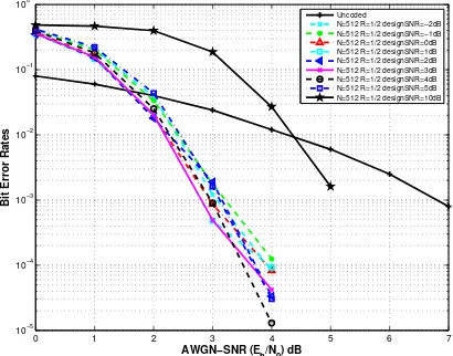
Figures 5 and 6 depict the performance of polar
codes produced for 512 at 1/2 and
5/6 respectively. Unlike small blocklengths,
it is shown that for 512 the BER becomes
more sensitive to design SNR. For instance, with
1/2 the BER degradation starts at design
SNR=5So and degrades dramatically when design
SNR reaches 10So. The uncoded system offers
better performance than the coded one in terms of
BER since SNR is less than 1.52So for 1/2
and less than 3.72So for 5/6 . It can be noted
that the candidate design SNR is 2So for 1/2
and 4So for 5/6.
[image:5.612.316.519.356.517.2]Figure 5: The BER sensitivity to design SNR for N=512 at R=1/2
Figure 6: The BER sensitivity to design SNR for N=512 at R=5/6
Figures 7 and 8 illustrate the performance of polar
codes produced for 2048 at 1/2 and
5/6 respectively. In this case the sensitivity of BER performance to design SNR becomes critical. Clearly, it is shown that the uncoded case offers better performance than the coded one in terms of
BER as long as SNR remains less than 1.4So for
1/2 and less than 3.5So for 5/6. From
the magnified part of curves, the candidate design
SNR is 2So for 1/2 and 4So for 5/6.
Unlike the candidate design SNR of 2So found in
our study for 1/2, the best design SNR
obtained in [6] is 0So for the same considered rate.
0 1 2 3 4 5 6 7
10−5 10−4 10−3 10−2 10−1 100
AWGN−SNR (Eb/N0) dB
Bit Error Rates
Uncoded N=64 R=1/2 designSNR=−2dB N=64 R=1/2 designSNR=−1dB N=64 R=1/2 designSNR=0dB N=64 R=1/2 designSNR=1dB N=64 R=1/2 designSNR=2dB N=64 R=1/2 designSNR=3dB N=64 R=1/2 designSNR=4dB N=64 R=1/2 designSNR=5dB N=64 R=1/2 designSNR=10dB
0 1 2 3 4 5 6 7
10−5 10−4 10−3 10−2 10−1 100
AWGN−SNR (E
b/N0) dB
Bit Error Rates
Uncoded N=64 R=5/6 designSNR=−2dB N=64 R=5/6 designSNR=−1dB N=64 R=5/6 designSNR=0dB N=64 R=5/6 designSNR=1dB N=64 R=5/6 designSNR=2dB N=64 R=5/6 designSNR=3dB N=64 R=5/6 designSNR=4dB N=64 R=5/6 designSNR=5dB N=64 R=5/6 designSNR=10dB
0 1 2 3 4 5 6 7
10−5 10−4 10−3 10−2 10−1 100
AWGN−SNR (Eb/N0) dB
Bit Error Rates
Uncoded
N=512 R=1/2 designSNR=−2dB N=512 R=1/2 designSNR=−1dB N=512 R=1/2 designSNR=0dB N=512 R=1/2 designSNR=1dB N=512 R=1/2 designSNR=2dB N=512 R=1/2 designSNR=3dB N=512 R=1/2 designSNR=4dB N=512 R=1/2 designSNR=5dB N=512 R=1/2 designSNR=10dB
0 1 2 3 4 5 6 7
10−6 10−5 10−4 10−3 10−2 10−1 100
AWGN−SNR (Eb/N0) dB
Bit Error Rates
Uncoded
[image:5.612.94.296.403.569.2]1403
Figure 7: The BER sensitivity to design SNR for N=2048 at R=1/2
Figure 8: The BER sensitivity to design SNR for N=2048 at R=5/6
As recapitulation, increasing blocklength makes BER performance sensitive to design SNR. Design SNR is indeed critical to construct polar code with a good BER performance. This has been already
stated in [6] but only for blocklength 2048
and code rate 1/2. To avoid confusion and
[image:6.612.323.517.97.221.2]stress the differences, let us summarize the results in Table 2. The candidate design SNR corresponds to a selected value according to the discrete search method.
Table 2: Sensitivity of BER to design SNR
Parameter name
Value Value Value
32 1/2 Low -1
32 5/6 Low 0
64 1/2 Medium 2
64 5/6 Medium -1
512 1/2 High 2
512 5/6 High 4
2048 1/2 Very high 2 2048 5/6 Very high 4
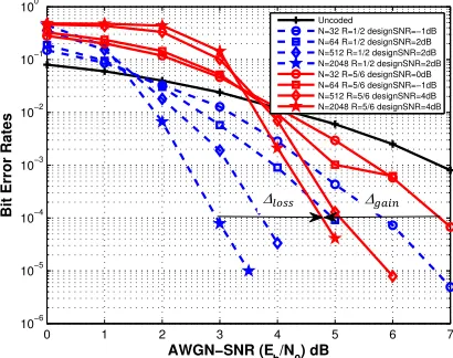
Figure 9 illustrates the construction chart for code
rates 1/2and 5/6. Clearly for a given code
rate , the higher blocklength is, the earlier the
[image:6.612.318.523.292.454.2]coded system outperforms the uncoded one.
Figure 9: Construction chart for code rates R=1/2 and R=5/6
The dashed curves demonstrate the BER
performance versus SNR for the code rate R 1/2.
If we increase the code rate to R 5/6, we come
up with the solid curves. While constructing polar
code with code rate R 5/6, increasing
blocklength from N 32 to N 2048 achieves
the SNR gain of ∆rstu 2.2dB at the BER of
10!x. For the blocklength of 2048, increasing code
rate from R 1/2 to R 5/6, changes the
operational SNR domain by ∆yz{{ 1.8dB at the
BER of 10!x. This trade-off sorted out must be
taken into consideration while designing polar codes for high-throughput application.
4. SUMMARY AND FUTURE WORK
This paper serves as a study of some aspect of polar codes. We performed a simple discrete search to find the best design SNR for Bhattacharyya parameter based construction. We then compared various BER performances and concluded that for
0 1 2 3 4 5 6 7
10−5 10−4 10−3 10−2 10−1 100
AWGN−SNR (Eb/N0) dB
Bit Error Rates
Uncoded
N=2048 R=1/2 designSNR=−2dB N=2048 R=1/2 designSNR=−1dB N=2048 R=1/2 designSNR=0dB N=2048 R=1/2 designSNR=0dB Harish et al. N=2048 R=1/2 designSNR=1dB N=2048 R=1/2 designSNR=2dB N=2048 R=1/2 designSNR=3dB N=2048 R=1/2 designSNR=4dB N=2048 R=1/2 designSNR=5dB N=2048 R=1/2 designSNR=10dB
0 1 2 3 4 5 6 7
10−5 10−4 10−3 10−2 10−1 100
AWGN−SNR (E
b/N0) dB
Bit Error Rates
Uncoded
N=2048 R=5/6 designSNR=−2dB N=2048 R=5/6 designSNR=−1dB N=2048 R=5/6 designSNR=0dB N=2048 R=5/6 designSNR=1dB N=2048 R=5/6 designSNR=2dB N=2048 R=5/6 designSNR=3dB N=2048 R=5/6 designSNR=4dB N=2048 R=5/6 designSNR=5dB N=2048 R=5/6 designSNR=10dB
0 1 2 3 4 5 6 7
10−6 10−5 10−4 10−3 10−2 10−1 100
AWGN−SNR (Eb/N0) dB
Bit Error Rates
Uncoded
N=32 R=1/2 designSNR=−1dB N=64 R=1/2 designSNR=2dB N=512 R=1/2 designSNR=2dB N=2048 R=1/2 designSNR=2dB N=32 R=5/6 designSNR=0dB N=64 R=5/6 designSNR=−1dB N=512 R=5/6 designSNR=4dB N=2048 R=5/6 designSNR=4dB
[image:6.612.93.296.307.468.2]ISSN: 1992-8645 www.jatit.org E-ISSN: 1817-3195
1404 short codeword length the effect of design SNR is less meaningful, for both moderate and high code rates. It is also observed that for long blocklength, design SNR have an enormous impact on BER performance for both moderate and high rates. Interestingly, under the same conditions, our best design SNR obtained is different from the optimal one found by [6]. In this work, the BER performance study is summarized to open the discussion on an important to-be developed issue, from the construction perspective. We hope this paper contributes to pave the path towards this end. The results shown are preliminary and the work needs to be carried out further to prove that the study is indeed viable for Rayleigh fading channel. We intend to investigate in a future work the performance analysis of the considered construction under orthogonal frequency-division multiplexing (OFDM). However, the decoding performance of SC algorithm is still not satisfying. We may obtain better performance using an iterative decoder. There is also a need to discuss the effect of initial value of Bhattacharyya parameter on system’s performance.
REFRENCES:
[1] Peiyao Chen, Minzi Xu, Baoming Bai and Xiao
Ma, “Design of polar coded 64-QAM”, 9th
International Symposium on Turbo Codes & Iterative Information Processing Design, IEEE,
2016, pp. 251-255.
[2] Liang Liu and Chuan Zhang, “Circuits and systems for 5g network: Massive MIMO and
advanced coding”, 11th International
Conference on ASIC (ASICON), IEEE, 2015, pp. 1-4.
[3] Talha Cihad Gulcu, Min Ye and Alexander Barg, “Construction of polar codes for arbitrary
discrete memoryless channels”, IEEE
International Symposium on Information Theory, 2016, pp. 51-55.
[4] Tao Wang, Daiming Qu and Tao Jiang,
“Parity-Check-Concatenated Polar Codes”, IEEE
Communications Letters, Vol. 7798, Issue c
2016, pp. 1-4.
[5] Erdal Arikan, “On the Origin of Polar Coding”,
IEEE Journal on Selected Areas in Communications, Vol.34, No. 2, 2016, pp. 209-223.
[6] Harish Vangala, Emanuele Viterbo and Yi Hong,
“A comparative study of Polar Code
Constructions for the AWGN Channel”, 2015, pp. 1-9.
[7] Ammar Hadi, Khaled M. Rabie and Emad Alsusa, “Polar codes based OFDM-PLC systems in the presence of middleton class-A
noise”, 10th International Symposium on
Communication Systems, Networks and Digital Signal Processing (CSNDSP), 2016.
[8] Pascal Giard, Gabi Sarkis, Alexios Balatsoukas-Stimming, YouZhe Fan, Chi-ying Tsui, Andreas Burg, Claude Thibeault and Warren J. Gross, “Hardware decoders for polar codes: An
overview”, IEEE International Symposium on
Circuits and Systems (ISCAS), 2016, pp. 149-152.
[9] Magali Bardet, Vlad Dragoi, Ayoub Otmani and Jean-Pierre Tillich, “Algebraic properties of polar codes from a new polynomial
formalism”, IEEE International Symposium on