ISSN: 1992-8645 www.jatit.org E-ISSN: 1817-3195
COMPACT FRACTAL MONOPOLE ANTENNA WITH
DEFECTED GROUND STRUCTURE FOR WIDE BAND
APPLICATIONS
1M V GIRIDHAR, 2T V RAMAKRISHNA, 2B T P MADHAV, 3K V L BHAVANI
1
M V REDDIAH BABU, 1V SAI KRISHNA, 1G V KRISHNA, 4S S MOHAN REDDY
1
M.Tech Project Students, Department of ECE, K L University, AP, India
2
Professor, Department of ECE, K L University, AP, India
3
Electrical Engineering Department, Santa Clara University, Santa Clara, USA
4
Associate Professor, SRKR Engineering College, Bhimavaram, India
E-mail: [email protected]
ABSTRACT
This letter presents a novel fan wing shaped uniform one dimensional fractal pattern antenna. The proposed antenna consisting of different inverted L-shaped elements to form a fan wing shaped structure. The design model achieved huge bandwidth characteristics with average gain of 4 dB. The simple structure of the proposed antenna with light weight makes it appropriate for many wireless communication applications. The simulated results on HFSS and measured results on ZNB 20 Vector Network Analyzer show that the proposed antenna has very good performance in impedance bandwidth and radiation pattern.
Keywords: Compact, Fractal Monopole Antenna, Wide bandwidth, Defected Ground Structure (DGS)
Wireless Communications.
1. INTRODUCTION
Fractals are geometrically shaped, which are self similar, repeating themselves at different scales. At the beginning these mathematical shapes where treated only as abstract curios tics until 1900’s. Then different branches of science discovered their practical applicability in different fields [1-5]. Soon after scientists discovered the practical of fractal geometric, research begin in the field of electro magnetics. This work produced successful devices for synthesis, modeling of microwave and mill metric waves. However, the main applications were for commercial telecommunications devices. These were compact antennas with properties such as broadband capability, frequency independent, small size and multi frequency operability. Other applications included fractal miniaturization of passive networks and components, fractal filters and resonators [6-10].
In the recent years, the geometrical properties of self similar and space filling nature has motivated antenna design engineers to adapt this geometry a viable alternative to meet the target of multi band operations [11-14]. In different papers microstrip
resonance-ISSN: 1992-8645 www.jatit.org E-ISSN: 1817-3195 mode increment, numerous monopole antennas
have been proposed by employing. The design and development of compact wideband antennas with advanced techniques like DGS are very much needed for the modern communication gadgets to place the structure in the case or cabin perfectly for easy carrying. Detected Ground Structures (DGS) as the name implies, refers to some compact geometries, commonly known as “unit cell” etched out as a single defect or in periodic configuration with small period number on the ground plance of a microwave printed circuit board (M-PCB) to attribute a feature of stopping wave propagation through the substrate over a frequency range. Thus a DGS can be described as a unit cell EBG or an EBG with limited shapes and sizes with different frequency responses and equivalent circuit parameters. The presence of DGS under a printed transmission line actually perturbs the current distribution in the ground plane and thus modifies the equivalent line parameters over the defected region. Thus it influences the guided wave characteristics and is found to exhibit
(1). Band gap properties as revealed due to EBG structures
(2) A slow wave effect which helps in compacting the printed circuits.
As mentioned earlier, the study of DGS can be classified under two categories depending on their configurations: (1) Single unit cell DGS; and (2) Uniform or non-uniform periodic arrangement of unit cells. Molding the structure as per the flexible communication requirement is needed in the design of antennas. This antenna model focused on this object with compact structure and DGS in the ground plane. Various promising feed structures such as the probe, the microstrip and the coplanar waveguide (CPW). In these presented monopole antennas, a large solid ground plane having the shape of a square, rectangle, circle, or ellipse is usually adopted. Different from this, a notable ground structure named defected ground structure (DGS) has recently been investigated and found to be a simple and effective method to reduce the antenna size as well as excite additional resonance modesIn this paper a novel fan wing shaped fractal antenna is proposed for wide band applications [17-18].
2. ANTENNA GEOMETRY
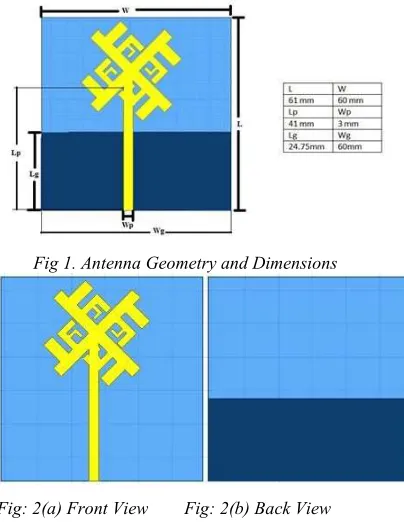
Fig 1 depicts the geometry of the proposed antenna. In first step the base shape is rotated by
[image:2.612.325.527.226.487.2]90°, 180° and 270° and connected with it is shown here. The bottom side of the antenna is taken as defected ground to improve the bandwidth as well as to suppress the losses. The fan wing shape is formed by placing different uniform fractal elements in a particular orientation. The proposed antenna is fabricated on FR4 substrate with dielectric constant 4.4 and loss tangent of 0.02. The antenna is fed by 50 Ω microstrip feed line with overall dimensions of 60mm×61mm.
Fig 1. Antenna Geometry and Dimensions
Fig: 2(a) Front View Fig: 2(b) Back View
Fig 2. Antenna orientation in front and back view
Figure 2(a) shows the front view of the Fractal Antenna and Fig 2(b) shows the bottom side of the Antenna model with defected ground structure. Ground plane is partially filled with conducting material to get the additional resonant frequency with enhancement in the bandwidth.
ISSN: 1992-8645 www.jatit.org E-ISSN: 1817-3195
3. RESULTS & DISCUSSION:
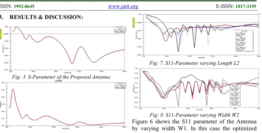
Fig: 3. S-Parameter of the Proposed Antenna
Fig: 4. VSWR of the Proposed Antenna
[image:3.612.92.531.71.294.2]Figure 3 shows the reflection co-efficient of the proposed Antenna with simulation tool HFSS. It has been observed that the Antenna is showing wide bandwidth of 45 GHz with characteristics from 5 GHz to 50 GHz, except the some of the mobile communication applications, the proposed Antenna is covering all other remaining communication bands up to 50 GHz. Figure 4 shows the VSWR characteristics of the proposed Antenna with 2:1 ratio in the operating band. Figure 5 shows the S11 parameter of the proposed Antenna with change in length L1. Except for the length L1=33.2 mm for all the remaining cases Antenna is showing almost 43 GHz to 45 GHz bandwidth, for length = 33 mm it is showing optimal characteristics.
Fig: 5. S11-Parameter varying length L1
Fig: 6. S11-Parameter varying width W1
Fig: 7. S11-Parameter varying Length L2
Fig: 8. S11-Parameter varying Width W2 Figure 6 shows the S11 parameter of the Antenna by varying width W1. In this case the optimized dimensions for W1 are found to be 4 mm. By varying Length L2, the return loss characteristics of the antenna are plotted in fig 7. For Length L2 = 33.5 mm Antenna is showing better reflection co-efficient characteristics parametric Analysis is done for the case of varying width W2 and the corresponding results are plotted in fig 8.
Fig: 9. Radiation pattern (a) 0.915GHz; (b) 13.2 GHz; (c) 16.2 GHz; (d) 19 GHz
[image:3.612.319.531.379.533.2] [image:3.612.91.305.494.672.2]ISSN: 1992-8645 www.jatit.org E-ISSN: 1817-3195
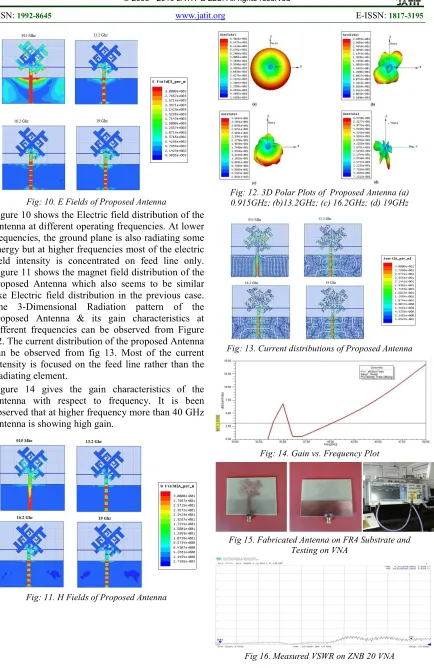
Fig: 10. E Fields of Proposed Antenna
Figure 10 shows the Electric field distribution of the Antenna at different operating frequencies. At lower frequencies, the ground plane is also radiating some energy but at higher frequencies most of the electric field intensity is concentrated on feed line only. Figure 11 shows the magnet field distribution of the proposed Antenna which also seems to be similar like Electric field distribution in the previous case. The 3-Dimensional Radiation pattern of the proposed Antenna & its gain characteristics at different frequencies can be observed from Figure 12. The current distribution of the proposed Antenna can be observed from fig 13. Most of the current intensity is focused on the feed line rather than the Radiating element.
[image:4.612.98.532.66.734.2]Figure 14 gives the gain characteristics of the Antenna with respect to frequency. It is been observed that at higher frequency more than 40 GHz Antenna is showing high gain.
Fig: 11. H Fields of Proposed Antenna
Fig: 12. 3D Polar Plots of Proposed Antenna (a) 0.915GHz; (b)13.2GHz; (c) 16.2GHz; (d) 19GHz
Fig: 13. Current distributions of Proposed Antenna
Fig: 14. Gain vs. Frequency Plot
Fig 15. Fabricated Antenna on FR4 Substrate and Testing on VNA
ISSN: 1992-8645 www.jatit.org E-ISSN: 1817-3195
Fig 15 shows the prototyped antenna model on FR4 substrate. The front view with respect to fractal element and the back view with respect to defected ground structure are presented here. The fabricated antenna is tested on ZNB 20 vector network analyzer and measured VSWR plot is presented in Fig 16.
The gain of the antenna is little bit low at lower operating band, which is a small drawback in this model. To overcome this problem, we can place frequency selective surface beneath the antenna structure as reflector to improve gain. Going for array model is another option, but the overall size of the antenna will increase and for compact devices that particular model may not be suitable in operation.
4. CONCLUSION
A compact fan wing shaped fractal monopole Antenna is designed and its operational characteristics are reported in this work. The proposed Antenna consisting of fractal patch on front side & defected ground structure on bottom side to improve the bandwidth characteristics. Antenna is showing high Bandwidth of 45 GHz with impedance bandwidth of 180 %. The Gain of the Antenna is also very high at higher frequencies and considerable at lower frequencies. The current antenna is suitable for the high frequency applications like satellite communication and tracking. Due to low gain at lower band the proposed antenna is not suitable for L and S-band applications. The compact nature with low weight makes this antenna more suitable for high end communication applications where high bandwidth is very much needed.
5. ACKNOWLEDGEMENTS
Authors like to express their gratitude towards the department of ECE and management of K L University for their continuous support during this work. Further Madhav likes to express his gratitude to DST through FIST grant SR/FST/ETI-316/2012.
REFERENCES:
[1] Islam MT, et al., 2012. Triple band-notched planar UWB antenna using parasitic strips: Progress In Electromagnetics Research, 129: 161-179.
[2] Lakshmi, M. L. S. N. S., et al., 2015. Analytical Study on Folded-Slot Koch Fractal
Antenna: Indian Journal of Science and Technology, 8(17): 66573-66578.
[3] Liu L, et al., 2011. A compact circular-ring antenna for ultra-wideband applications: Microwave and Optical Technology Letters, 53(10): 2283-2288.
[4] Madhav, B.T.P., et al., 2014. Fractal aperture EBG ground structured dual band planar slot antenna: International Journal of Applied Engineering Research, 9(5): 515-524.
[5] Madhav, B.T.P., VGKM Pisipati, Habibulla Khan, D Ujwala., 2014. Fractal shaped Sierpinski on EBG structured ground plane: Leonardo Electronic Journal of Practices and Technologies, 13(25): 26-35.
[6] Madhav,B.T.P, et al., 2015. Circularly Polarized Koch Fractal Triband Antenna for Communication Applications: ARPN Journal of Engineering and Applied Sciences, 10(14): 5795-5801.
[7] Mohan Reddy,S.S., et al., 2015. Partial Substrate Removal Techniques for the Enhancement of Gain and Radiation Characteristics in Fractal Antenna: Research Journal of Applied Sciences, Engineering and Technology, 10(1): 79-85.
[8] Phani Srinivas, K., et al., 2015. Novel Koch fractal circularly polarized micro strip antenna for global positioning system application: Leonardo Electronic Journal of Practices and Technologies, 27(2): 31-40.