First-Principles Study of the Electronic Properties of
=
0Interface
in Ni Based Superalloys
Cuiyu Geng
1, Chongyu Wang
1;2;3, Jian-Tao Wang
4and Tao Yu
11
Central Iron and Steel Research Institute, Beijing 100081, P. R. China
2Department of Physics, Tsinghua University, Beijing 100084, P. R. China
3International Center for Materials Physics; Academic; Shenyang 110016, P. R. China 4Institute of Physics, Chinese Academy of Sciences, Beijing 100080, P. R. China
Electronic properties of the H-, B- and C-doped=0interface in Ni based Superalloys are studied by means of the self-consistent
full-potential linearized augmented-plane-wave method under generalized gradient approximation. It is shown that all the three impurities, H, B and C prefer to occupy the Ni-rich octahedral interstitial sites at the=0interface. The calculated charge transfer suggests that the effect of H, B and
C on the=0interface is localized. For the B and C cases, due to the hybridization between the p states of the impurity and the d states of the
nearest-neighbor nickel atoms, the effect of both B and C is to strengthen the =0 interface. In contrast, for the H case, the H-s/Ni-d
hybridization results in a strong weakening of interplanar bonding and a slight enhancement of intraplanar Ni–Ni bonding on the interface planes, so that the effect of H is to decrease the cohesive strength of=0interface.
(Received December 20, 2004; Accepted March 22, 2005; Published June 15, 2005)
Keywords: superalloy, interface, ab initio calcualtuion, electronic structure
1. Introduction
Ni-base single-crystal superalloys, which have remarkable properties at elevated temperature, have been widely used in aircraft engines and land-based gas turbines for a range of applications. Nowadays, the most advanced single crystal alloys of the second and third generations are used at temperature up to 1100C, mostly as turbine blades. The key
to the outstanding high temperature properties of the Ni-base single-crystal superalloys is the L12 0 intermetallic phase Ni3Al that is coherent with the face-centred-Ni-rich solid solution matrix. Therefore, the =0 interfaces play an
important role in the behavior of the Ni-based superalloys used in the aeronautic industry.
Many trace alloying additions may be present (by accident or design) in Ni-base superalloys. These impurities, including B, C, N, H, O, P and S, etc., have greatly affected the strength and ductility of high-temperature materials.1,2)The effect of elements such as B, H and C on the properties of superalloys is complex and dependent on the chemical composition of the alloy and the heat treatment history. Small additions of boron are essential to improved creep-rupture resistance of super-alloys,3) whereas the role of H in superalloys has been
generally believed to be detrimental. Carbon provides a source of carbides, and carbon additions are determined to influence the segregation behavior of the constituent alloys and affect some aspects of the mechanisms that lead to solute-induced fluid flow.4)Clearly, more investigation on the
interaction between trace elements and interfaces is neces-sary in order to understand the behavior of these alloys under thermal and/or mechanical loading.
Since the interactions between interfaces and trace elements to a large extent control the properties of Ni-base single-crystal superalloys, understanding the electronic structure of the =0 interface doped with impurities is of the utmost importance in the development of novel alloys with superior mechanical properties. In spite of considerable
theoretical efforts have been made to understand the effect of impurities on the mechanical behavior of bulk or grain boundary (GB) in Ni and Ni3Al on the basis of the electronic structure,5–12)not many efforts have been made to investigate the fundamental mechanism of the=0interface. Up to now,
only few first-principles calculations on the =0 inter-face13–16)have been carried out. Previous works have greatly extended our knowledge about the elementary mechanism of the =0 interface. However, some fundamental problems
such as the electronic structure mechanism of B, H and C at the interface, are still far from being fully understood and should be clarified. In addition, the influence of local environments of the impurity atom on the electronic structure of the=0interface has not been studied. In this paper, in an
attempt to better understand the alloying effects of these trace elements (e.g., B, H and C), we presents a detailedab initio
study on the=0interface in Ni based superalloys.
The paper is organized as follows. In Sec. 2, we briefly describe the computational method used in our calculation. Sec. 3 presents the effect of the local environment of the impurity on the electronic structures, such as charge density, density of states (DOSs) with and without B, C and H at the =0 interface. Finally, a brief summary and statement of
conclusions are presented in Sec. 4.
2. Computational Method
All calculations reported in this paper are performed using the self-consistent full-potential linearized augmented-plane-wave method (FLAPW)17,18)based on the density functional
theory19,20)without spin polarization. The FLAPW method is
renowned to be one of the most precise electronic structure and total energy method.21)In the FLAPW method, the core states are treated fully relativistically and the valence states are treated semirelativistically. The total and partial DOSs are obtained using a modified tetrahedron method of Blo¨chl
et al.22)All the results are calculated under the generalized Special Issue on Computer Modeling of Materials and Processes
gradient approximation (GGA)23)with 400 k-points mesh in the Brillouin zone. The Muffin-Tin radius 2.0 a.u. are chosen for both Al and Ni atoms, while Muffin-Tin radii for B, H and C atoms are chosen as 1.3, 1.0 and 1.3 a.u., respectively. The energy cutoff of 12 Ry for the augmented plane-wave basis to describe the wave functions in the interstitial region, and a 400 Ry cutoff for the star functions depicting the charge density and potential are used. The convergence criterion is set as104Ry.
In consideration of the real precipitated state of 0 phase
from matrix and referring to reference,24) we employ a coherent=0interface supercell model without mismatch to
simulate the =0 interface approximately. The supercell
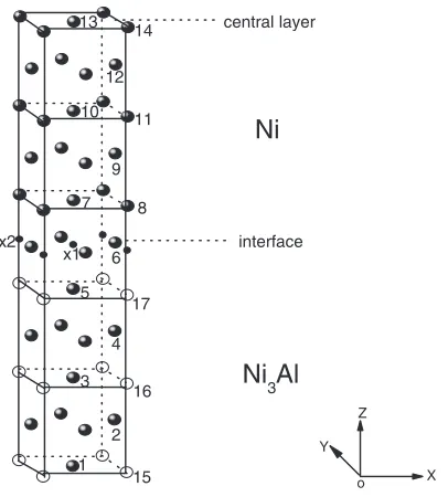
have two identical interfaces, consists of twenty atomic layers in the [001] direction as shown in Fig. 1. The interaction between two adjacent interfaces is expected to be sufficiently weak with nine atomic layers spacing. For the sake of the symmetry, the supercell is doped with two impurity atoms, i.e. one impurity atom for each interface. -Ni and 0-Ni
3Al have the FCC and L12 structures, respectively. Nonequivalent atoms in the cell are denoted by numerical label, depending on their point-group symme-try. Based on the experiment25)and theoretical calculation,7)
and also for the purpose to consider the effect of the local environment of the impurity on the electronic structure, the impurity atoms (labeled by X) are placed at two different octahedral interstitial sites: X1 at the center of the octahedral cell, where the impurity has the nearest neighbors of four Ni (6) and one Ni (7) and one Ni (5), and X2 at the center of the cube edge, where the impurity has the nearest neighbors of four Ni (6), one Ni (8) and one Al (17). We will refer to the X1 and X2 sites as the Ni-rich and Ni-deficient octahedral sites, respectively. To correctly understand the electronic
properties, the impurity-doped supercells as well as the undoped supercell are relaxed with the variation in the lattice constant, while the interplanar spacings is fixed with the bulk value. The equilibrium lattice constant a for the undoped supercell obtained by the FLAPW method is 0.3532 nm as shown in Fig. 2.
3. Results and Discussions
In order to study the effect of the local environment of the impurity on the electronic structure, we consider two different types of octahedral sites X1 and X2 (see Fig. 1). To compare the energies of various impurities and config-urations, the impurity formation energy is defined as
Eimp¼EtotðNi35Al5X2Þ EtotðNi35Al5Þ 2EtotðXÞ;
whereEtot(Ni35Al5X2) andEtot(Ni35Al5) are the total energy with and without the impurity X atoms, respectively.Etot(X)
are the total energy of an isolated impurity atom.
In Table 1, the impurity formation energies of H, B and C at two different types of octahedral sites are estimated. It is seen from the table that all the impurity formation energies at the Ni-rich octahedral site X1 are much more negative than those corresponding energies at the Ni-deficient octahedral site X2. Thus we conclude that all the impurities prefer to occupy the Ni-rich octahedral sites X1 that are completely surrounded by the nearest-neighbor Ni atoms. Our result is consistent with the finding of Sunet al.7)who showed that
both boron and hydrogen prefer to occupy the entirely Ni-coordinated octahedral interstitial sites in Ni3Al.
In order to understand the effect of impurities on the=0
interface, we next, consider the redistribution of charge induced by the impurity atom when it is placed at the Ni-rich octahedral site X1. This can be best described by the
Ni
3Al
interface
Ni
central layer 14
13
12
11 10
9
7 8
6 x2
x1
17 5
4 3
16
2 1
15 o
Y Z
X
Fig. 1 Supercell model for the=0 interface. Only half of the supercell
along the Z direction is displayed with one interface at the center of the diagram. The solid, open and smaller solid circles represent Ni, Al and X atoms, respectively (X stands for the hydrogen, boron, or carbon impurity). The two types of octahedral sites for the impurity are denoted by X1 and X2, respectively.
0.340 0.345 0.350 0.355 0.360 0.365 0.370
-108884.25 -108884.20 -108884.15 -108884.10 -108884.05 -108884.00 -108883.95
Energy,
E
/Ry
lattice constant, l/nm
Fig. 2 The total energy as a function of lattice constant for the =0
[image:2.595.307.546.72.232.2]interface supercell.
Table 1 The impurity formation energies (in eV/unit cell) for H, B and C at two different types of octahedral sites.
Octahedral sites H B C
X1 5:284 8:931 9:574
X2 4:346 7:246 7:734
[image:2.595.70.273.495.720.2] [image:2.595.304.548.745.784.2]difference of bonding charge density between supercells of undoped and impurity-doped=0interface, namely
imp ¼solidðNi35Al5X2Þ solidðNi35Al5Þ 2atomðXÞ:
We will refer to imp as the impurity-induced charge
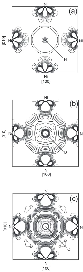
density. The impurity-induced charge density on the (110) and on the interface planes is shown in Figs. 3 and 4, respectively. Here solid and dotted curves represent contours of increased and decreased charge densities. For the convenience of comparison, we use the contour spacing 0.0001 e a.u.3 in Figs. 3(a)–(c) and 0.002 e a.u.3 in Fig-s. 4(a)–(c), respectively.
In Fig. 3(a), it can be seen that the charge density around the impurity H is strongly decreased by the presence of H, indicating the decreasing of the bond strength between host metal atoms. This feature was also found in bulk Ni3Al7)and GB in Ni3Al.9)From Fig. 4(a) we can see that H induces a weak enhancement of the interstitial bonding between the nearest-neighbor Ni (6) sites, thus slightly increasing the intraplanar Ni–Ni bonding on the interface planes. The overall effect of H is to decrease the cohesive strength of the =0interface.
Contrary to the case of hydrogen, from Fig. 3(b), we see the charge density induced by B in the interstitial region between Ni (7) and Ni (8) is obviously increased. Therefore, the relatively strong bonds are formed between Ni (7) and Ni (8), increasing the cohesive strength of the interface. The boron-induced charge density on the interface plane is shown in Fig. 4(b). Compared with the hydrogen case, there is a substantial enhancement of interstitial bonding charge between the nearest-neighbor Ni (6) sites, leading to increasing the intraplanar Ni–Ni bonding on the interface planes. From the above analysis, we can conclude that there is a covalent bonding between B and Ni. It is shown that the covalent bonding to be responsible for the beneficial effect of B on the strength of the=0interface. Thus B atom acts as a cohesion enhancer at the =0 interface and improves the
strength of the interface. In Fig. 3(c) and Fig. 4(c), we find that the charge density changes induced by C additions are similar to those due to the presence of boron impurity at the interface. Therefore, the carbon impurity, similar to the boron impurity, is also a cohesion enhancer to the=0interface.
It is well known that the charge transfer between the impurity element and the host atoms play a great role on the interatomic bonding behavior. So the valence charge, partitioned by sites, is given in Table 2. From Table 2 one can see that for the H doped system, only the
neatest-(c)
(b)
(a)
100 100
C
Ni Ni
Ni
Al Al
Al Al
Al Al
Ni
Ni Ni
Ni Ni
Ni Ni
[0
01]
[110] 100
10
Ni Ni
100 100
B Ni
Ni
Ni
Ni
Al(17) Al(17)
Al(16) Al(16)
Al(15) Al(15)
Ni Ni(8) Ni(8) Ni(11) Ni(11) Ni(14) Ni Ni(14)
[00
1
]
[110] 100 100 100
100
100 100
H Ni Ni
Ni
Ni
Al Al
Al Al
Al Al
Ni
Ni Ni
Ni Ni
Ni Ni
[00
1
]
[110] 100
100 Ni
Fig. 3 Impurity-induced charge density plotted on the (110) plane: (a) H, (b) B, and (c) C. The impurity atom is located at the X1 site. The contour spacing is 0.0001 e a.u.3. Solid lines and dashed lines correspond to the gain and the loss of electrons, respectively.
(c)
(b)
(a)
C Ni
Ni
Ni Ni
[010
]
[100] B Ni
Ni
Ni Ni
[010]
[100]
Ni
Ni Ni
[010
]
[100] H Ni
[image:3.595.345.505.70.590.2] [image:3.595.52.290.74.267.2]neighbor nickel sites on the interface plane [Ni (6)] have a remarkable charge accumulation, for all the other sites the charge transfer is too small to account for. While for the B (or C) doped system, the presence of B (or C) induces a significant charge accumulation in the nearest-neighbor nickel sites [Ni (5), Ni (6) and Ni (7)]. There is very little change in the charge of the other more distant atoms. The charge transfer listed in Table 2 indicates that the effect of impurities (hydrogen, boron and carbon) is localized.
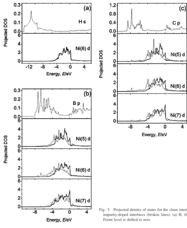
To complete the analysis of the interactions between impurities and host atoms, we have further calculated the DOSs. According to the charge transfer information in Table 2, thel-projected DOSs for the impurity atom and the Ni atoms in the impurity-doped =0 interface supercells
(dotted lines) are shown in Figs. 5(a)–(c). The DOSs for the undoped supercell (solid lines) is also given for comparison. As it is known very well, Ni-d states provide the dominant contribution to the total DOSs of Ni atoms. So here we only present the Ni-d DOSs for Ni atoms. Some features can be noted here. First, the s DOSs of H is pushed far below the Fermi level, thus the H (s)–Ni (d) hybridization contributes little to the binding between H and Ni. The changes in the DOSs induced by H are very small for the Ni (6) atoms, only a small downward shift in the Ni (6)-d band. However, there is a strong hybridization between the B-p (or C-p) and Ni (5)-, Ni (6)- and Ni (7)-d states. We see that the d DOSs of the host Ni atoms are greatly moved towards the lower energy direction as a result of the B (p)–Ni (d) (or C (p)–Ni (d)) hybridization. This is consistent with the charge transfer listed in Table 2. From Figs. 5(a)–(c), we also find that the DOSs at the Fermi level decreases due to the addition of B (or C), while the DOSs of the H-doped interface supercell at the Fermi level is very similar to that of the undoped interface. As we know the reduction of the DOSs near the Fermi level means that the transition probability of electronic states is confined; thus the addition of B (or C) may be beneficial to
the stability of the=0interface. Based on above
observa-tion, we understand that H does not improve the cohesion of the=0interface. Our DOSs analysis is consistent with the
other results obtained in the present calculation.
4. Summary
We have performed first-principles calculations to study the effect of H, B and C doped in the=0interface. We find
that all the three impurities prefer to occupy Ni-rich octahedral sites that are completely surrounded by the nearest-neighbor Ni sites. Moreover, the effect of all the three impurities on the interface electronic structure is localized. In the H case, the changes in the DOSs induced by H are very small. The intraplanar Ni–Ni bonding on the interface planes is slightly increased, whereas the interplanar bond strength between host metal atoms is strongly decreased by the addition of H. So it is concluded that the overall effect of H is to decrease the cohesive strength of the=0interface. In contrast, the addition of B (or C) results in the DOSs shifting towards lower energy part and a reduction of the DOSs near the Fermi level. Furthermore, we also find the intraplanar bonding and the interplanar bonding between the host metal atoms are enhanced due to the impurity-p/Ni-d hybridization. Thus we conclude that B and C act as a cohesion enhancer to the=0interface.
Acknowledgements
The authors would like to thank Professor P. Blahaet al.
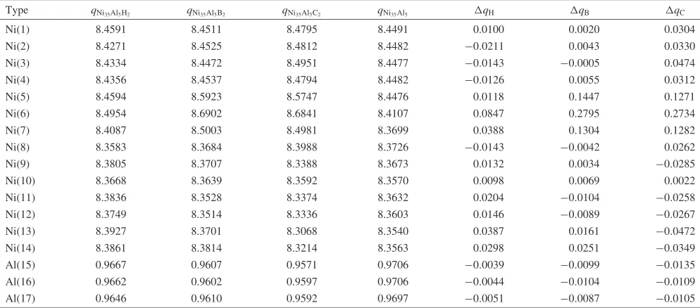
[image:4.595.49.546.105.324.2]for providing us their first-principles program WIEN2k. This work is supported by ‘‘973 Project’’ from the Ministry of Science and Technology of China (Grant No. TG2000067102) and the National Natural Science Foundation of China (Grant No. 90306016, 901041044). Table 2 The total valence charge for nonequivalent host atoms inside Muffin-Tin spheres for the doped supercells (impurity located at X1
sites) and for the clean Ni35Al5supercell. The last three columns are the valence charge difference,q, between the impurity-doped and clean Ni35Al5supercells.
Type qNi35Al5H2 qNi35Al5B2 qNi35Al5C2 qNi35Al5 qH qB qC
Ni(1) 8.4591 8.4511 8.4795 8.4491 0.0100 0.0020 0.0304
Ni(2) 8.4271 8.4525 8.4812 8.4482 0:0211 0.0043 0.0330
Ni(3) 8.4334 8.4472 8.4951 8.4477 0:0143 0:0005 0.0474
Ni(4) 8.4356 8.4537 8.4794 8.4482 0:0126 0.0055 0.0312
Ni(5) 8.4594 8.5923 8.5747 8.4476 0.0118 0.1447 0.1271
Ni(6) 8.4954 8.6902 8.6841 8.4107 0.0847 0.2795 0.2734
Ni(7) 8.4087 8.5003 8.4981 8.3699 0.0388 0.1304 0.1282
Ni(8) 8.3583 8.3684 8.3988 8.3726 0:0143 0:0042 0.0262
Ni(9) 8.3805 8.3707 8.3388 8.3673 0.0132 0.0034 0:0285
Ni(10) 8.3668 8.3639 8.3592 8.3570 0.0098 0.0069 0.0022
Ni(11) 8.3836 8.3528 8.3374 8.3632 0.0204 0:0104 0:0258
Ni(12) 8.3749 8.3514 8.3336 8.3603 0.0146 0:0089 0:0267
Ni(13) 8.3927 8.3701 8.3068 8.3540 0.0387 0.0161 0:0472
Ni(14) 8.3861 8.3814 8.3214 8.3563 0.0298 0.0251 0:0349
Al(15) 0.9667 0.9607 0.9571 0.9706 0:0039 0:0099 0:0135
Al(16) 0.9662 0.9602 0.9597 0.9706 0:0044 0:0104 0:0109
Al(17) 0.9646 0.9610 0.9592 0.9697 0:0051 0:0087 0:0105
REFERENCES
1) R. T. Holt and W. Wallace: Int. Met. Rev.,21(1976) 1–24. 2) C. G. Bieber and R. F. Decker: Trans. AIME,221(1961) 629–636. 3) Superalloy, edited by M. J Donachie and S. J. Donachie: American
ASM International 2002, (2002) 27–28.
4) S. Tin, T. M. Pollock and W. T. King: superalloys2000, ed. by T. M. Pollock, R. D. Kissinger, R. R. Bowmanet al., (TMS, 2000) 201–210. 5) G. S. Painter and F. W. Averill: Phys. Rev. Lett.58(1987) 234–237. 6) D. A. Muller, S. Subramanian, P. E. Batson, S. L. Sass and J. Silcox:
Phys. Rev. Lett.75(1995) 4744–4747.
7) S. N. Sun, N. Kioussis, S.-P. Lim, A. Gonis and William H. Gourdin: Phys. Rev. B52(1995) 14421–14430.
8) F. H. Wang, C. Y. Wang and J. L. Yang: J. Phys. Condens. Matter8 (1996) 5527–5537.
9) F. H. Wang and C. Y. Wang: Phys. Rev. B57(1998) 289–295. 10) G. Lu, N. Kioussis, R. Wu and M. Ciftan: Phys. Rev. B59(1999) 891–
898.
11) F. H. Wang, J. X. Shang, J. M. Li and C. Y. Wang: Intermetallics8 (2000) 589–293.
12) Q. M. Hu, R. Yang, D. S. Xu, Y. L. Hao, D. Li and W. T. Wu: Phys. Rev. B67(2003) 224203(1)–223203(9).
13) D. L. Price and B. R. Cooper: M.R.S. Proc.,408(1996) 463–470.
14) Y. Liu, K. Y. Chen, G. Lu, J. H. Zhang and Z. Q. Hu: Acta Mater45 (1997) 1837–1849.
15) K. Chen, L. R. Zhao and John S. Tse: Philos. Mag.83(2003) 1685– 1696.
16) K. Chen, L. R. Zhao and John S. Tse: Mater. Sci. Eng. A360(2003) 197–201.
17) P. Blaha, K. Schwarz, G. Madsen, D. Kvasnicka and J. Luitz: Computer Code WIEN2k (Vienna University of Technology, Vienna, 2003) 33– 136.
18) P. Blaha, K. Schwarz, P. Sorantin and S. B. Trickey: Comput. Phys. Commun.,59(1990) 399–415.
19) P. Hohenberg and W. Kohn: Phys. Rev. B136(1964) 864. 20) W. Kohn and L. J. Sham: Phys. Rev. A140(1965) 1133–1138. 21) D. J. Singh: Planewaves, Pseudopotentials and the LAPW Method,
Kluwer Academic, Boston, MA (1994) 23–54.
22) P. Blo¨chl, O. Jepsen and O. K. Andersen: Phys. Rev. B49(1994) 16223–16233.
23) J. P. Perdew, K. Burke and M. Ernzerhof: Phys. Rev. Lett.77(1996) 3865–3868.
24) I. L. Mirkin and O. D. Kancheev: Met. Sci. Heat Treat.1/2, (1967) 10– 18.
25) N. Masahashi, T. Takasugi and O. Izumi: Acta Metall.36(1988) 1815– 1822.
[image:5.595.107.480.68.524.2]