Effects of Roll Diameter and Offset on Sectional Shape
of Square Steel Pipe Processed by Roll Forming
*Takuo Nagamachi
1, Takefumi Nakako
2and Daisuke Nakamura
21Institute of Technology and Science, The University of Tokushima, Tokushima 770-8506, Japan 2Steel & Technology Development Laboratories, Nisshin Steel Co., Ltd., Sakai 592-8332, Japan
A square steel pipe is reshaped from a welded round pipe by roll forming. We investigated the effect of the roll diameter on the cross-sectional size of the square steel pipe by experimentation and three-dimensional finite element (FE) simulation. When the diameters of the top and bottom roll pairs are larger than those of the pair of side rolls, the cross section width of the formed pipe is less than the height. To equilibrate them, we perform finish forming at the final stage. Furthermore, the width of corner part of the formed pipe is greater than its height. The difference between these two sizes of width and height of the corner part in the final product is greater than those at upstream stands and increases with the ratio of the diameter of top and bottom roll pairs to that of side roll pairs. Offset the smaller roll pairs upstream makes the pipe square. Such offset is effective for producing pipes with equal width and height at the corner. [doi:10.2320/matertrans.P-M2011828]
(Received May 23, 2011; Accepted September 22, 2011; Published November 25, 2011)
Keywords: roll forming, square steel pipe, roll diameter, offset, finite element (FE) simulation
1. Introduction
Square shaped steel tubes, mainly produced by roll forming, are used widely as structural elements of buildings and machines. Generally in the forming process, a roll set, a top and bottom pair and a side pair, is arranged. Then three roll sets are connected tandemly. A circular pipe is pushed into the almost square-shaped holes of the center of the roll set. Bent corners and re-bent sides are formed in the cross section of the circular pipe. Then the circular pipe is changed to a square pipe. On this subject, Kiuchi et al.1) have
conducted a series of experimental studies. Onoda et al.2)
reported an investigation that was performed based on their analyses to date.
When designing a roll-forming machine for square steel tubing production, the diameter of the paired top and bottom rolls is usually set as larger than that of the side roll pair. Thereby interference is avoided between the roll axes driven by electric motors. The longitudinal length of the contact domain between the paired top and bottom rolls and work is greater than that between the paired side rolls and work because that length increases with the roll diameter. We speculate that the longitudinal length of the contact has a definite influence on the width and height and dimensional precision of the corner region, although a thorough explana-tion is unavailable.
The authors performed an experiment and FE simulation in the roll forming process of square-shaped steel tubing for the condition with different diameters of rolls between top and bottom roll pairs and those of side roll pairs. Based on the result, we evaluated the roll diameter effect on the dimen-sional precision of the pipe height, width, and corner.3) Kondo et al.4) devised a new arrangement of roll pairs to extend the adjustable distance of roll gaps in four-roll forming of the wire and bar, in which axes of two sets of roll
pairs were shifted longitudinally (offset roll forming). We applied this offset roll forming to production of square shaped steel tubing to improve the dimensional precision of the corner region; thereby, we validated that method through experimentation and analysis.5)
2. Experiment and Analysis
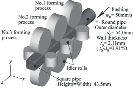
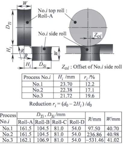
Figure 1 presents a schematic view of the forming process used for this study. The ram of an oil pressure cylinder pushes the circular pipe into the almost square-shaped roll holes of the center of each roll set of Nos. 1, 2, and 3, and a square steel pipe is discharged from the last roll set. No rolls are driven in this process. Names of rolls and their dimensions are listed in the insets of Fig. 2. The top and bottom rolls are Roll A at all times. Roll A, Roll B, Roll C, and Roll D are examined as side rolls. The respective ratios of diameters of top and bottom rollsDTito that of side rollsDSiof these four
configurations areDTi=DSi¼1:0, 1.5, 2.0, and 3.0. Here, we
define the geometric contact length, shown in Fig. 3, as a parameter to represent the roll diameter and configuration.
Fig. 1 Schematic illustration of forming processes.
*This Paper was Originally Published in Japanese in J. JSTP52-603 (2011) 495–499.
[image:1.595.311.540.617.769.2]These values of the i-th process, LTi and LSi, might be
calculated using the following equations, respectively, for top and bottom rolls and side rolls.
LTi ¼
ffiffiffiffiffiffiffiffiffiffiffiffiffiffiffiffiffiffiffiffiffiffiffiffiffiffiffiffiffiffiffiffiffiffiffiffiffiffiffiffiffiffiffiffiffiffiffiffiffiffiffiffiffiffiffiffiffiffiffiffiffiffiffi DTi
2
2
DTi
2 Hi1þHi
2
s
ð1Þ
LSi¼
ffiffiffiffiffiffiffiffiffiffiffiffiffiffiffiffiffiffiffiffiffiffiffiffiffiffiffiffiffiffiffiffiffiffiffiffiffiffiffiffiffiffiffiffiffiffiffiffiffiffiffiffiffiffiffiffiffiffiffiffiffiffiffi DSi
2
2
DSi
2 Hi1þHi
2
s
ð2Þ
Nomenclature is presented in Fig. 2 and for the No. 1 process (i¼1)Hi1¼H0¼d0=2 (circular pipe radius). The ratios
of the geometric contact length of top and bottom rolls LTi
and to that of side rolls LSi of these four configurations LTi=LSi are depicted in Fig. 3. As might be expected, the
greaterDTi=DSiis, the greaterLTi=LSiis.
Table 1 presents the result of tensile test of test piece cut from the circular tube we used, which is STK400 galvanized steel tube.
Our calculation procedure is depicted in Fig. 4. The simulation was conducted using a static implicit scheme applied to transient elasto-plastic analysis. Before analysis, we conducted forming experiments of each stand (Nos. 1, 2, and 3) independently to confirm that sectional profiles of rolled works from each stand were almost identical to those of tandem roll forming. Analysis was done for each stand in two steps to save machine time. In the first step, the work is placed in the square roll hole, which is opened wider than2Hi
in both x and ydirections with the constraint of the fixed work head. Then the upper roll is lowered to attain work height =Hi and the side roll is moved to attain work
width =Hi(press process). In the second step, the tail of the work moves in thezdirection with the removed constraint of the fixed work head (pass process). Although the rotational speed of rolls is unknown in advance, it is adjusted by the constraint of zero torque force on the roll axes. The longitudinal lengths of the analysis domains of Nos. 1, 2, and 3 are, respectively, 150 mm, 120 mm and 100 mm. The forming lengths of the pass process in each stand are, respectively, 100 mm, 85 mm and 80 mm.
We regarded the cross-sections at 50 mm, 42.5 mm, and 40 mm from the head of work as those of steady pass process in each stand. The analysis domain for FE is cut by hexahedral elements with eight nodes. Three elements are
Fig. 2 Notations and dimensions of rolls.
Fig. 3 Definition of geometrical contact length (LTi;LSi).
[image:2.595.68.276.71.311.2] [image:2.595.319.526.92.436.2] [image:2.595.59.283.349.533.2] [image:2.595.77.293.613.677.2]allocated in the thickness direction. The total number of elements was 15,000–20,000. Here, 0.12 was assumed as the coefficient of coulomb friction. A general-purpose code of DEFORM-3D Ver. 6.0 was used for calculations for 12 hr to 24 hr on a PC with a Core 2 3.0 GHz processor (Intel Corp.).
3. Results and Discussion
3.1 Influence of roll diameter on cross-section dimen-sions
Although dimensions of the cross-section that had passed three stands are important, we examined the pipe that had passed just the No. 1 stand and that which had passed No. 1 and No. 2 stands to evaluate the effects of upstream deformations on cross-sectional dimensions of the final product. The nomenclature for cross-sectional dimensions of the formed pipe is shown in Fig. 5. In that figure,hxandhy
respectively denote the pipe width and pipe height both from the center O; andhais the average of these two. We designate
the part of periphery that made contact with the roll as the side, that which made no contact as the corner and the
boundary of these two parts as the shoulder. The width and height of the corner (part between two shoulders) are designated respectively assxandsy;sais the average of these
two.
First, the influence of roll diameter on pipe widthhxand
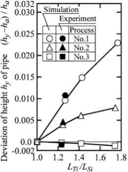
heighthyis discussed. Figure 6 depicts the relation between
deviation ofhyfromha,ðhyhaÞ=ha, and the ratioLTi=LSiof
the geometric contact length of top and bottom roll pairs to the side roll pairs.ðhyhaÞ=haof the No. 1 stand marked by
grows with LTi=LSi, which indicates a vertically longer
rectangular cross-section of product. It might be explained by bending of sides longitudinally as follows. For the No. 1 side roll, thex-zsectional view aty¼0(center of side) around the contact zone is portrayed in Fig. 7(a), and the distribution of the longitudinal curvature at the center of thickness in Fig. 7(b). As portrayed in Fig. 7(a),x-zsection aroundy¼0
(center of side) is bent outward first and is then bent back in the opposite direction on contact with the roll. For large roll diameter like that of Roll A, that curvaturel1at the contact
zone (16mmz0mm) attains a value that is approx-imately equal to the geometrical configuration of roll and
Fig. 5 Notation representing cross-sectional shape of formed pipe.
Fig. 6 Effect of roll diameter on cross-sectional shape of formed pipe.
[image:3.595.362.492.72.246.2] [image:3.595.117.220.75.233.2] [image:3.595.135.461.294.484.2]work (t0thick)2=ðDS1þt0Þ. In a small roll diameter such
as Roll D, that curvature at the contact zone (8mm z0mm) attains a value that differs greatly from 2=
ðDS1þt0Þ. In this configuration, the side sinks inwardly and
the product cross-section becomes a vertically long rectangle. In the No. 3 stand, in contrast, the distortionðhyhaÞ=hais
approximately 0 (almost a truly square cross-section) for every setting ofLTi=LSi, as depicted in Fig. 6 by a mark.
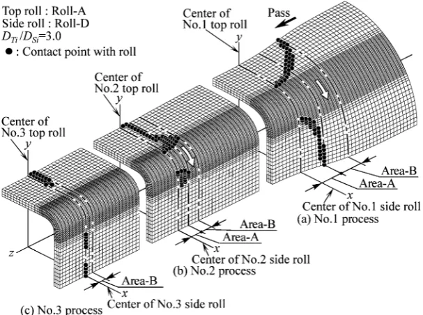
This apparent lack of distortion might be explained by the difference in contact between the pipe and roll as follows. Figure 8 shows the calculated deformed pipe shape and pattern of contact domain forDTi=DSi¼3:0. The increment
of reduction (r3r2presented in Fig. 2) of No. 3 stand is as
small as 2.5%. Consequently, at this stand, elements making contact with top and bottom rolls and side rolls ( ) are limited and localized around the z position of roll axes. Therefore, the roll diameter at No. 3 stand only slightly influences the width and height of the product. In other words, it is advisable to perform forming with a small increment of reduction at the last stand to obtain an almost square pipe.
We next discuss the influence of the roll diameter on corner width sx and heightsy (cf. Fig. 5). Figures 9(a) and
9(b) respectively depict the average of sx and sy, sa, and
deviation ofsyfromsa,ðsysaÞ=sa. Both are shown against
the ratio of contact lengthLTi=LSi. In fact,sain Fig. 9(a) does
not change much withLTi=LSiand the influence ofLTi=LSion sais apparently slight. Nevertheless,ðsysaÞ=sain Fig. 9(b)
decreases with LTi=LSi and is negative for LTi=LSi>1:0, sx>sy. We designated this distortion as ‘‘corner droop’’. The absolute value ofðsysaÞ=saof the product formed by No. 3
stand marked as mark greatest for every value ofLTi=LSi,
and the droop is the greatest as well. The droop occurrence might be explained by contact between the pipe and roll as follows. Because of the difference in roll diameters between the top and bottom pair and side pair, lengths of longitudinal contact differ between two roll pairs and work. Both pairs of
rolls make contact with work in Area A of Fig. 8. In Area B of the same figure, only the top and bottom pair maintain contact with the work and hold it. Therefore, the corner is displaced in the direction indicated by white arrows in Fig. 8. This displacement in that direction was confirmed earlier as the node movement in FE simulation.3) Consequently, the
shoulder region of the top side goes away from the corner center by this displacement, and that of the side approaches it. Therefore,sx>sy.
3.2 Forming by longitudinally offset roll pairs
Kondoet al.4)described four-roll forming of wire and rods, whereby the longitudinal offset of axes of side roll pairs in the upstream direction (z direction) made the product wider horizontally. If we compare width expansion in Area B of Fig. 8 to that described above, then we might suppress the width expansion in Area B by offset of axes of side roll pairs in the upstream direction and thereby reduce corner droop.
Fig. 8 3-dimensional shapes and contact areas (simulation results).
[image:4.595.146.450.72.298.2] [image:4.595.307.545.345.533.2]Figure 10 demonstrates the effect of forming with side rolls offset described above on the droop of corner for No. 1 stand. The quantity of offsetZoiis presented in Fig. 2. It is the
difference ofzpositions between two pairs of rolls axes. In Fig. 10, it is normalized by the average geometrical length of the roll-work contact (defined in the same figure) asZoi=Lai.
For each value of LT1=LS1, ðsysaÞ=sa decreases and
approaches zero. Corner droop is removed, as expected. Large DT1=DS1 and therefore large LT1=LS1 require large
offsetZo1to remove corner droop. However, formation with
an overly large offset brings about opposite droop with
ðsysaÞ=sa>0, generating reverse droop with sx<sy.
Corner droop reduction by offset might be explained by roll-work contact as follows. Figure 11 depicts the deforma-tion of work and roll contact at stand No. 1 forDT1=DS1¼ 2:0andZo1 ¼9:0mm obtained through FE analysis. A new
type of domain of Area C appears in which only side rolls come in contact with the work. Top and bottom rolls do not
touch the work in Area C, as shown in the figure. There, the work is held solely by side rolls and the corner is pushed up. Thereby, the corner droop is reduced.
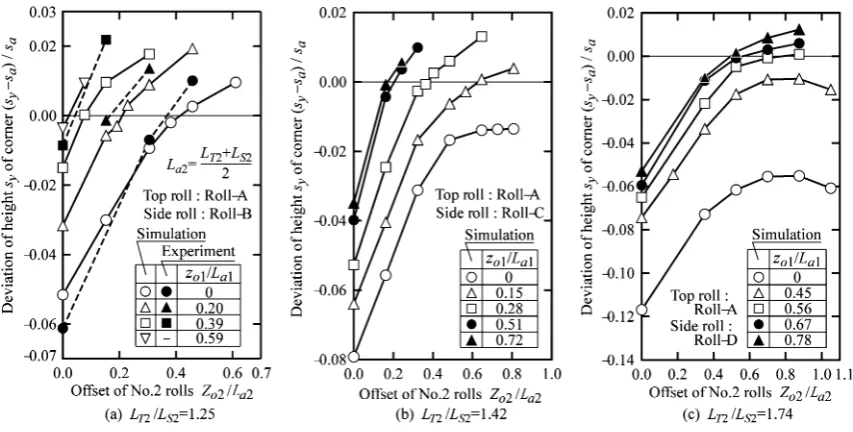
Figure 12 demonstrates ðsysaÞ=sa after repeated offset
forming by stands No. 1 and No. 2.Zo2in this figure is again
normalized by the average geometric contact length ofLa2.
At points marked by in Fig. 12, offset at No. 1 stand is zero, Zo1=La1¼0, meaning that the offset is done only at
stand No. 2. In Fig. 12(a) forLT2=LS2¼1:25points marked
by and mark for the case ofZo1=La1¼0 might attain ðsysaÞ=sa¼0 by setting Zo2=La2¼0:4. Therefore, for LT2=LS2 close to unity, droop is removed by offset only at
the No. 2 stand. However, for the cases of Fig. 12(b) with
LT2=LS2¼1:42 and Fig. 12(c) with LT2=LS2¼1:74, ðsy saÞ=sa¼0 is never attained merely by increasing Zo2 if Zo1=La1¼0(mark ). Therefore, for large value ofLT2=LS2,
[image:5.595.78.261.71.271.2]corner droop is removed only by combined offset at both stands Nos. 1 and 2.
[image:5.595.311.540.75.226.2]Fig. 10 Effect of offset on deviation of corner shape of pipe formed by No. 1 rolls.
[image:5.595.84.511.317.533.2]Fig. 11 3-dimensional shapes and contact areas of pipe formed by offset method in No. 1 process (simulation results).
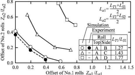
Because the increment of reduction at No. 3 stand is very small, the additional change in corner shape is small as well, as shown in Fig. 9(b). This fact suggests that forming work with small droop only by stands Nos. 1 and 2 is advisable to get eminent product of small droop. We can find the combinations of offsets at Nos. 1 and 2 stands to obtain products without corner droop by two stands from simula-tions and experiments presented in Fig. 12. They are demonstrated in Fig. 13. It is likely that formation of products without corner droop can be accomplished by applying the combinations of offsets on the curves in Fig. 13. In future studies, we shall examine the influence of the reductionriat each roll and the initial thicknesst0of circular
pipe on offset forming.
(3) Offset forming in which roll pairs with smaller diameter are offset in the upstream direction is effective to produce tubes with equal width and height of the corner part.
REFERENCES
1) M. Kiuchi, K. Shintani and M. Tozawa: J. JSTP21-231 (1980) 339–346 (in Japanese).
2) Y. Onoda, T. Nagamachi and T. Sugiyama: J. JSTP36-409 (1995) 149– 154 (in Japanese).
3) T. Nagamachi, T. Nakako and D. Nakamura: Proc. 2007 Japanese Spring Conf. for the Technology of Plasticity, (2007) pp. 131–132 (in Japanese).
4) H. Kondo, R. Takeda, K. Ohmori and N. Kunita: Kawasaki Steel GIHO, 28-2 (1996) pp. 69–75 (in Japanese).
[image:6.595.54.285.73.201.2]