Abstract— The shock absorber, which is part of the
suspension structure, represents a rather complex element from the constructive point of view as well as for the role it plays in the car structure.
On the one hand, from constructive point of view, this contains between 40 and 150 component parts. On the other hand, because they are precision parts the technical conditions of component parts are exigent.
The shock absorber can be classified according to different criteria, but this is not the aim of our paper. Taking into account the various types of shock absorbers, this paper proposes solutions for the improvement of their design process in order to improve the quality of the product during the designing, manufacturing and exploitation phases.
This paper makes an analysis of the parametrized design possibilities of the single components from the shock absorber assembly in order to standardize all processes involved and to make them more efficient.
The parameters design procedure of the shock absorber implies the use in the absorbers assembly of the single components previously designed with parameters.
By using the single components previously designed with parameters in the final assembly structure, there is the possibility to use these parameters even into the final assembly. These parameters modify the geometries of the single components in order to create new components, based on the existing ones.
Index Terms—Shock Absorber, CATIA and Parameter
I. INTRODUCTION
HE shock absorber is part of the vehicle suspension
whose aim is to reduce the shocks generated by the road surface on which the vehicle runs. The shock absorber connects the unsprung mass (which is represented by the
Manuscript received January 08, 2016; revised February 17, 2016. This work was supported in part by Alexandru-Marcel MOLDOVAN, Romania, Mihail Aurel ȚÎȚU from Lucian Blaga University of Sibiu and Niculae Ion MARINESCU from Politehnica University of Bucharest.
Alexandru-Marcel MOLDOVAN is Ec. Sc.D. Student at “Lucian Blaga” University of Sibiu and is the manager of the Technical Department from ThyssenKrupp Bilsten Compa S.A. from Sibiu (e-mail:
[email protected] / [email protected]). Mihail Aurel ȚÎȚU is Professor at “Lucian Blaga” University of Sibiu (Faculty of Engineering) and is Director of the Intellectual Property Department of the University and Director of the European PATLIB Centre (corresponding author to provide phone: +40269430110, e-mail:
Niculae Ion MARINESCU is Professor at “Politehnica” University of Bucharest.
vehicle chassis) and sprung mass (which is represented by its body).
The shock absorber has to generate enough force to be able to ensure the control of the unsprung mass and that of the movements of the sprung mass while the vehicle runs on the road surface.
Also, the shock absorber should be able to ensure the outer geometrical interface which has to allow the proper fitting with the:
- vehicle body, - steering knuckle, - helical spring,
- stabilizing bar supports,
- cable supports (break and sensors), - mounting bolts,
- etc.
Analyzing the role the shock absorbers have in the entire suspension structure, we see that:
- on the one hand, the shock absorber has to ensure the stability of the vehicle while being operated, at the same time ensuring the comfort of the passengers and the goods carried by the vehicle;
- on the other hand, the shock absorber may need to ensure additional functionalities such as: carry the suspensions spring; be an active element in steering mechanism, (McPherson), be an element that could ensure the link with the stabilizing bar, etc.
These functions that were identified for a shock absorber to perform, represent the input data in the design process.
These identified functions which a shock absorber has to perform, represent the input data in the design process. Thus, during the designing phase, one will measure the damping characteristic and then design the outer geometrical interface. The damping characteristic is generated by the piston road assembly together with the bottom valve assembly.
In order to make a proper design of the new types of telescopic shock absorbers, be it original equipment or after-market equipment, it is necessary to have deep knowledge of the elements which influence quality and sustainability during their entire lifetime. Furthermore, it is necessary to know how to choose the damping characteristic and level for a certain type of suspension, according to [1].
Out of the several types of telescopic shock absorbers which are going to be mentioned in the next chapter, this
Redesigning Car Shock Absorbers Using
Parameterized Components for Improving
Functioning Quality
Moldovan Alexandru-Marcel, Țîțu Aurel Mihail and Marinescu Niculae Ion
paper analyzes only the design of a bi-tubular, passive, telescopic shock absorber with gas for the rear axis which is schematically represented in figure 2. In figure 2 are also named the main component parts of the above mentioned shock absorber.
Since we are particularly going to talk about the design process used in the CATIA software (Computer Aided Three dimensional Interactive Applications) we must mention the fact that the advantages of the design with parameters can be identified both in the bi-dimensional design (2D) and in the tri-dimensional design (3D).
Parametric design applies when creating families of parts with the same shape but which differ in size. Parametric design is also called Parametric Aided Design.
This approach facilitates technical decision making, reduces errors, it increases productivity and it automates the concept,as in [2].
[image:2.595.321.508.58.677.2]II. CLASSIFICATION OF THE TELESCOPIC SHOCK ABSORBERS
Fig. 1. Classification of the telescopic shock absorbers, according to [1]
As it can be noticed in figure 1, there are various types of shock absorbers. A classification of the shock absorbers can be made depending on the aim and function they have to perform. Another classification can also be made taking into account the type of the design system used. Depending on the scope of the designed and manufactured shock absorbers, two types of markets have been identified, namely: the original equipment and after-market equipment. This classification tries to emphasize the fact that it is highly necessary to have an approach to standardize the working processes, even in the designing phase. This can also be applied to the absorber which is, from a constructive point of view, the most simple but complex none the less.
The shock absorber which is from a constructive point of view the simplest is made out of about 40 component parts.
The most complex shock absorbers are made out of about 150 component parts. Because they are precision parts the technical conditions for these component parts are exigent.
[image:2.595.47.289.286.442.2]III. APPROACH
From a constructive point of view, according to the frequency of using the component parts in the final assembly, two categories can be identified:
Parts which are permanently used in the shock absorber assembly and without which a shock absorber cannot function;
Parts which are not permanently used in the shock absorber assembly and without which a shock absorber can function, but these parts fulfill additional roles besides its shock absorption function.
In the category of component parts without which a shock absorber cannot function, the following parts are included:
- Sleeve; - Guiding; - Piston rod;
- Piston rod assembly; - Inner tube;
- Outer tube;
- Bottom valve assembly; - Lower cap.
In the category of component parts which can be found in the final assembly and have additional functions besides the shock absorption function, the following parts are included:
- Bonded bush; - Bracket; - Spring seat; - Bracket stabilizer; - Dust cover; - Cable holders; - Bump stop; - Etc.
In the parameterized design, an approach to standardize the component parts is represented by analyzing the frequency of their usage in order to analyze their impact on the design time and on the improvement of their quality.
In most cases, when creating a new component, the user begins by building a sketch which gives the model (part), on which different parametric data can be added, as in [2].
The design with parameters does not refer only to the improvement of the design process. This also represents an approach to standardize the single components and to create groups of components based on a pattern-model. By means of the pattern-model the design process and working standards can be practically defined.
The design with parameters method has a direct influence on the production processes because starting from them the equipment and production devices can be standardized. Thus, much more efficient modular devices can be developed that could be used for the entire range of products.
Another advantage is represented by the fact that the parts are developed as groups of parts and represent a support for the purchasing and logistics processes. As the purchasing process is concerned, the purchase is made easier due the fact that one can negotiate the entire group of parts. One might want to change the supplier of an entire category of parts, the outer tube for example. In this case, it is very easy for the Purchasing Department to handle the entire group of the above mentioned part than to handle each part individually.
Likewise, for the Department of Logistics, the process of handling the individual parts compared to the process of handling the group of parts becomes much efficient.
The management of the technical documentation and its codification represents a key factor for the standardization of the designing and production process. The codification of the technical documentation can significantly be simplified after applying a standardized working style.
Although these topics are sensitive enough and would deserve an additional research, this paper focuses on the process of component parts standardization.
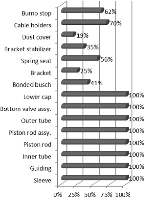
The below chart in figure 3 represents the frequency in using the single components in the final assembly even if they are or are not indispensable in the functioning process of the shock absorber.
Following this analysis, it results that more than half of the component parts of a shock absorber can be found in all the shock absorbers because they are indispensable in the oscillation reducing process performed by a shock absorber. Knowing this, the design with parameters can play a very important role in improving the quality during the design, manufacturing and exploitation phases.
[image:3.595.316.549.359.679.2]This paper analyzes in detail this aspect by identifying the parameters which have to be programmed for each single component.
Below, the geometries of the dimensions of each single part are listed:
Sleeve:
Outer diameter;
Inner diameter.
Guiding:
Contact outer diameter of the guiding with inner of the outer tube;
Contact outer diameter of the guiding with inner diameter of the inner tube;
Contact inner diameter of the guiding with outer diameter of piston rod;
Height. Piston rod:
Outer diameter;
Length;
The geometry of top area which connects with vehicle body;
The geometry of lower area which connects
with piston.
Piston rod assembly:
Outer diameter;
Inner diameter;
Height;
Number of shims;
Outer diameter of shims;
Thickness of shims. Inner tube:
Outer diameter;
Inner diameter;
Length; Outer tube, as in [3]:
Length;
Outer diameter;
Inner diameter;
The geometry from the guiding area;
The geometry from the lower cap area;
The geometry between guiding and lower cap, named tube geometry;
Crimping.
Bottom valve assembly:
Contact outer dimeter of the bottom valve with inner diameter of inner tube;
Contact diameter with lower cap;
Number of shims;
Outer diameter of the shims;
Thickness of shims.
Lower cap:
Contact diameter with bottom valve;
Outer diameter;
Thickness.
Bonded bush:
Length;
Inner diameter;
Outer diameter; Bracket:
Contact inner diameter of bracket with outer diameter of outer tube;
Bolts diameter. Spring seat:
Contact diameter with outer tube;
Thickness. Bracket stabilizer:
Contact diameter with outer tube;
Thickness;
Contact diameter with stabilizer bar. Dust cover:
Outer diameter;
Thickness;
Length. Cable holders:
Contact diameter with outer tube;
Thickness.
Bump stop:
Outer diameter;
Inner diamater;
Length.
After identifying these parameters, a pattern-model can be designed for each single part. Thus, each pattern-model will contain the parameters necessary for completely defining each part. Whenever a new part is needed to be designed, a pattern-model of each part will be used. Then, the geometries of the part under discussion will be changed through the existing parameters previously created and linked to the geometries.
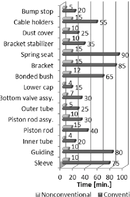
After analyzing figure 3, it results that, if the most frequently used parts from the shock absorber assembly are designed with parameters, the impact on the design time is maximum and thus, the design time of the final assembly is significantly reduced.Consequently, maximum benefits are obtained with a minimum of effort.
As an observation, when talking about the design time, the design activity must only be taken into account, namely the drawing of the part under discussion. This paper does not treat the research activity which should be carried out in order to develop/test the parts under discussion.
Depending on its complexity, according to the conventional procedure, a shock absorber is designed in about 500 minutes. This happens in the case when all parts have to be designed from the beginning.
However, a shock absorber does not have to be designed from the very beginning in each case, but there are parts which can be taken over from other projects, thus promoting the standardization concept.
When designing a project, other new parts might have to be developed, too. This happens either because the exterior geometry is identical with that of another existing project but the damping forces differ, or because both the exterior geometry and the damping forces must be designed from the very beginning.
According to the conventional procedure, shown in figure 4, the shock absorber assembly – depending on its complexity – is designed in 8 hours on average, compared to the unconventional procedure, the time of designing decreases depending on each used part designed with parameters.
Figure 4. Required design time for different type of parts
From the designing quality point of view the 3D models designed with parameters have the following advantages: - they contain all the geometries necessary to use them in any other new project;
- they allow the possibility to change the dimensions, geometries and characteristics (for instance: material proprieties, etc.) of a part in order to use it easily in any other new project.
From the designing quality point of view the 2D drawings designed with parameters have the following advantages: - they contain all the technical conditions specific to a certain part; thus, there is no need to design a drawing from the very beginning;
- the parametric dimensions are literary noted on the drawing with the table containing the literary dimensions specific to each (new) part.
The drawings and models designed with parameters are created according to the mandatory quality requirements. Any other new part that automatically derives from them has the required quality.
IV. CONCLUSION AND NEXT RESEARCHES
Parametric aided design does not only increase design quality and design productivity, it also influences manufacturing process and its standardization, acquisitions and logistics departments.
This redesign approach (minimal effort with maximum benefits) can also have influence on improving functioning quality, the present approach being but the first step to this end. The next steps to fulfill this efficiency are represented by the research topics described below:
Tabular input data, recorded into a data base such as Microsoft Excel or ASCII, to be linked with the parameters from a 3D model. So that, by changing the data from the data base, the 3D could automatically update its geometry;
Standardization of technical documentation and of drawing codification to be in direct correlation with parameterized design.
REFERENCES
[1] I. Drăghici, “Suspensions and shock absorbers (Suspensii si
amortizoare),” Technical Publisher Bucharest, 1970, pp. 25-31.
[2] I. G. Ghionea, “CATIA v5 – Collection of applications for laboratory activities (CATIA v5 – Culegere de aplicatii pentru activitati de laborator),”, Politechnical University of Bucarest, v.1.5, 2015, pp.92. [1] Moldovan Alexandru-Marcel, Țîțu Aurel Mihail and Marinescu
Niculae Ion, Improved Process on Development Phase of Outer Tube
Component from a Shock Absorber Structure, Lecture Notes in