Abstract— The permanent magnet synchronous motor (PMSM) has emerged as an alternative to the induction motor because of the reduced size, high torque to current ratio, higher efficiency and power factor in many applications. Space Vector Pulse Width Modulation (SVPWM) technique is applied to the PMSM to obtain speed and current responses with the variation in load. This paper analysis the structure and equations of PMSM, SVPWM and voltage space vector process. The Model Reference Adaptive System (MRAS) is also studied. The PI controller uses from estimated speed feedback for the speed senseless control of PMSM based on SVPWM with MRAS. The control scheme is simulated in the MATLAB/Simulink software environment. The simulation result shows that the speed of rotor is estimated with high precision and response is considerable fast. The whole control system is effective, feasible and simple.
Index Terms— PMSM, Space vector pulse width modulation, model reference adaptive system.
I. INTRODUCTION
HE demand for variable speed drives in both low and
high power applications has resulted in a great variety of products from different manufacturers, each offering a great variety of features. In this respect, the control strategy plays a great role in fulfilling the demands of each application. Modeling and simulation is usually used in designing permanent magnet drives compared to building system prototypes because of the cost. Having selected all components, the simulation process can start to calculate steady state and dynamic performance and losses that would have been obtained if the drive were actually constructed. This practice reduces time, cost of building prototypes and ensures that requirements are achieved.
The PMSM drive requires two current sensors and an absolute rotor position for the implementation of any control strategy. The rotor position is sensed with an optical encoder or a resolver for high performance applications.
Manuscript received April 09, 2014; revised April 17, 2014.
Pradeep Kumar is with the Department of Electrical Engineering, International group of Institutions, Sonepat, Haryana, India. e-mail:[email protected]
Mandeep Kumar is with the Department of Electrical Engineering, Hindu College of Engineering, Sonepat, Haryana, 131001, India. e-mail:[email protected]
Surender Dahiya is with the Department of Electrical Engineering, Deenbandhu Chhotu Ram University of science & Technology, Murthal, Sonepat, Haryana, 131039, India. e-mail: [email protected], phone 91-941-629-4032.
The position sensors compares to the cost of the low power motor and also reduce the motor efficiency. Thus making the total system cost very noncompetitive compared to other types of motor drives we are using sensor less speed control of PMSM. Position sensor could be bulky and may malfunction in harsh environment.
A speed controller has been designed for closed loop operation of the drive. A MRAS based sensor less control system is designed using the space vector pulse width modulation (SVPWM) of the PMSM motor in the MATLAB/Simulink [1-3, 6-8]. The MRAS adaptive speed estimator is easy to implement that we are using in this paper. The goal of this paper is to design and implement a normal drive system of a permanent magnet synchronous motor (PMSM).
II. SVPWM OFPMSM
The objective of space vector pulse width modulation (SVPWM) of PMSM is to control the torque variation demand, rotor speed and to regulate phase currents. The goal of SVPWM in synchronous machine is to separately control the torque and magnetizing flux producing components. SVPWM promotes us to decouple the torque and magnetizing components of stator current [4]. With this decoupling, the torque producing components of the stator flux now can be thought of as an independent torque control. It is necessary to engage several mathematical transforms for decoupling these components.
In general the SVPWM consist of controlling the stator current represented by a vector. This control is based on several mathematical transforms in which a three phase time and speed dependent system is converted into a two co-ordinate time variant system. SVPWM makes the control accurate in every walking operations (steady state or transient) and independent of the limited band with mathematical model [5].
Equations of Permanent Magnet Synchronous Motor
The stator current equations of the PMSM is in the rotating d-q reference frame are as follows-
d
1
d d q.
qd d d
s
r
d
R
L
i
u
i
i
dt
L
L
L
(1)q
1
q q d d fq q q q
s
r r
d
R
L
i
u
i
i
dt
L
L
L
L
(2)
Sensor Less Speed Control of PMSM using
SVPWM Technique Based on MRAS Method
for Various Speed and Load Variations
Pradeep Kumar, Mandeep Kumar, and Surender Dahiya
T
e
1.5
P
f qi
L
q
L i i
d
d q
(3)m
1
e m L
d
T
B
T
dt
J
(4)
r
p
m (5)Equations (1-3) are electrical equation, while equation (4) is mechanical equation. Where f
rotor magnetic flux dL
d-axis stator inductance qL
q-axis stator inductance sR
stator resistance eT
electromagnetic torque LT
load torque m
mechanical speed r
angular speedJ
moment of inertiaB
coefficient of frictionp
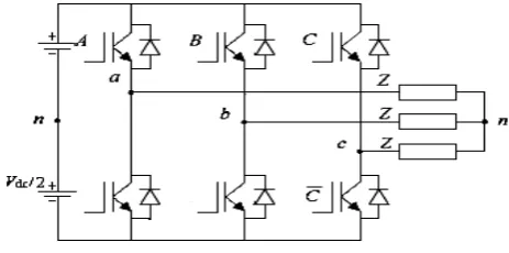
no. of poles III. PRINCIPLEOFSVPWM Space vector control is the process to generate a pulse-width modulation signal for PMSM voltage signal. In this technique the inverse Clarke transform has been folded into the space vector modulation routine which simplifies the equation . Each of the three output of inverter can be in one of the two states which allows for 23 =8 possible states of output as shown in Table I SVPWM subjects to generate a voltage vector which is close to a reference circle through different switching modes of inverter [6]. Fig. (1) shows the basic diagram of three phase voltage source inverter (VSI) model. Fig. 1. Basic Voltage Source Inverter The space vector of output voltage of inverter can be given as [9-10]: VA(SA,SB,SC) = 2Vdc(SA+αSB+α2SC)/3 (6)Where Vdc is DC bus voltage of inverter and α is ej/20. If the state of upper and lower arm switches is considered 1 and 0 respectively, then the on-off state will have eight possible Combination voltage space vectors as shown in Fig. 3. T-refers to the operation time of two non-zero voltage vectors in the same zone. V0(000) and V7(111) are called zero voltage space vector, while remaining six vectors are known as effective vectors with magnitude of 2Vdc/3 [11]. TABLE I Inverter states SA SB SC A dc
V
V
B dcV
V
C dcV
V
01
2
3
4
5
6
7
0 0 0
0 0 1
0 1 0
0 1 1
1 0 0
1 0 1
1 1 0
1 1 1
0 -1/3 -1/3 -2/3 2/3 1/3 1/3 0
0 -1/3 2/3 1/3 -1/3 -2/3 1/3 0
0 2/3 -1/3 1/3 -1/3 1/3 -2/3 0
[image:2.595.56.288.555.670.2]
Fig. 2.Voltage Space Vector Diagram
IV. SIMULINK SIMULATION OF SVPWM
Based on the principle of SVPWM, the simulation models for generating SVPWM waveforms mainly include the sector judgment model, calculation model of operation, time for fundamental vectors, calculation model of switching time, and generation model of SVPWM waveforms.
(i). Sector judgment
To apply the technology of SVPWM, firstly it is requested to determine the sector which the voltage vector is within. Considering that the expression of vector in the α-β
coordinate is suitable for controlling implementation, the following procedure is used for determining the sector [6]. When
V
when3
V
V
when3
V
V
C
. Then the sector containing the voltage vector can be decided according to N=A+2B+4C, listed in table II. Fig.3 shows the corresponding model.TABLE II
THE SECTOR CONTAINING THE VOLTAGE VECTOR VERSUS N
Fig. 3. Model of sector judgment
(ii).Calculation of operation time of fundamental vectors Table III listed the operation times of fundamental vectors against N, where T1 and Tm refer to the operation times of
two adjacent non zero voltage space vectors in the same zone. Fig. 4 shows the calculation model, where
( 3
)/( 2 ),
dc( 3
)/( 2 ),
dc2 [ /( 2 )]
dcZ T
V V
V Y T V V
V X TV
V
.
The sum of T1 and Tm must be smaller than or equal to T
(PWM modulation period). The over saturation state must be judged: if
1 m
,
T
T
T
take1 1
[ / (
1 m)],
m m[ / (
1 m)]
T
T T
T
T
T
T T
T
T
Fig. 5. illustrates the SIMULINK-based model.TABLE III
OPERATION TIME OF FUNDAMENTAL VECTOR
N 1 2 3 4 5 6
T1 Z Y -Z -X X -Y
Tm Y -X X Z -Y -Z
Fig. 4. Model for counting X,Y,Z.
Fig. 5. Calculation model of operation times of fundamental vectors
(iii). Generation of SVPWM Waveform
The relation between N and switch operation times is realized in Fig. 6, where
T
a
(
T
T
1T
m) / 4
,1
/ 2
b a
T
T
T
,andT
c
T
b
T
m/ 2
,T
cm1,T
cm2 and 3cm
T
are the operation times of three phases respectively.Fig. 6. Model of switch operation time
Fig. 7. Model of relation between N, Tcm, Ta, Tb and TC and generation of
SVPWM waveform.
(iv). Calculation model of switch operation time
By comparing the computed Tcm1, Tcm2, and Tcm3 with the
[image:4.595.52.279.264.411.2]equilateral triangle diagram, a symmetrical space vector PWM wave form can be generated and its model shown in Fig. 7. The PMSM is controlled by switching on or off the power electronics parts. Fig. 8 illustrates the overall model of SVPWM.
V. PRINCIPLEOFMODELREFERENCEADAPTIVE SYSTEM
The MRAS is an important adaptive controller. In this controller the performance is expressed in terms of reference model (which is PMSM itself) which gives the desired response to a command signal. Block diagram of MRAS is shown in Fig. 9.
Fig. 9. Schematic Block of MRAS scheme
As the speed of rotor ω is included in these equations we can use the current model of PMSM as the adjustable model and PMSM itself as a reference model. Both of these models have output Id and Iq .Through a certain adaptive
mechanism, we can obtain the estimated value of speed and position of rotor [7].
The eqn. (1) and (2) can be written in the matrix form.
1
s
d s d d
q s q q
s
R
i
i
u
d
L
i
R
i
u
dt
L
L
(7)For the convenience of analysis of stability ωm has been compared to system matrix
R
L
A
R
L
(8)
Let
i
di
d rL
;i
qi
q (9)
u
du
dR
rL
;u
qu
q (10)The process of speed estimator can be described as follows:
ˆ
ˆ
ˆ
1
ˆ
ˆ
ˆ
d
d d
q
q q
R
u
i
i
d
L
R
u
dt
i
i
L
L
(11)
The error of the static variable is e=
i
i
ˆ
Above eqn. can be written as
d
i
ˆ
Ai
ˆ
ˆ
Bu
dt
(12)From the above mention eqn.
ˆ
can be obtained as[1-2]1
ˆ
ˆ
2ˆ
ˆ
ˆ
k i i
(
d qi i d
q d)
k i i
(
d qi i
q d)
ˆ
(0)
(13) When k1 and k20
Replace
i
d,i
q withi
d,i
q we get1
ˆ
ˆ
ˆ
ˆ
k i i
[
d qi i
q d r(
i
qi
q)]
d
L
k i i
2[
d qˆ
q d
ˆ
r(
qˆ
q)]
ˆ
(0)
si i
i
i
L
(14)In above equation
i
ˆ
d andi
ˆ
q are of adjustable model while di
,i
qcan be obtained from the stator currenttransformation.
The position of rotor can be is estimated by integrating the estimated speed. A complete sensor less control scheme based on MRAS is shown in Fig. 10.
Fig. 10. Sensor less control block diagram with MRAS system
VI. SIMULATIONANDRESULTS
Simulation is performed in the MATLAB Simulink. Simulation time is kept 0.4sec. Results are verified under different varying conditions.
1) When speed and load both are constant. 2) When speed is constant and load is varied. 3) When speed is varied and load is constant. 4) When speed and load both are varied.
[image:4.595.319.543.447.576.2]0 0.05 0.1 0.15 0.2 0.25 0.3 0.35 0.4 -1000
-500 0 500 1000 1500
time(S)
s
pee
d(
rpm
[image:5.595.51.556.56.181.2])
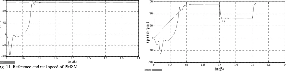
Fig. 11. Reference and real speed of PMSM
0 0.05 0.1 0.15 0.2 0.25 0.3 0.35 0.4 -20
-15 -10 -5 0 5 10 15 20
time(S)
to
rque
(N
M
)
Fig. 12. Electromagnetic torque of PMSM
For condition 2- When speed is constant and load is varied [speed is 1400rpm and load torque is 0-0.1sec(3NM), 0.1-0.2sec(1NM), 0.2-0.3sec(2NM), 0.3-0.4sec(3NM)].
0 0.05 0.1 0.15 0.2 0.25 0.3 0.35 0.4 -1000
-500 0 500 1000 1500
time(S)
spee
d(
rp
m
[image:5.595.48.561.214.337.2])
Fig. 13. Reference and real speed of PMS
0 0.05 0.1 0.15 0.2 0.25 0.3 0.35 0.4 -15
-10 -5 0 5 10 15 20
time(S)
to
rq
ue(
NM
[image:5.595.55.558.426.545.2])
Fig. 14. Electromagnetic torque of PMSM
For condition 3- When speed is varied and load is constant [speed is 0-0.1sec(0-1400rpm), 0.1-0.2sec(1400rpm), 0.2-0.3sec(800rpm), 0.3-0.4sec(1400rpm) and load torque is 3NM].
0 0.05 0.1 0.15 0.2 0.25 0.3 0.35 0.4
-1000 -500 0 500 1000 1500
time(S)
s
pe
ed(
rpm
)
Fig. 15. Reference and real speed of PMSM
0 0.05 0.1 0.15 0.2 0.25 0.3 0.35 0.4
-15 -10 -5 0 5 10 15 20
time(S)
to
rq
u
e
(N
M
)
Fig. 16. Electromagnetic torque of PMSM
For condition 4- When speed and load both are varied [speed is 0-0.1sec(0-1400rpm), 0.1-0.2sec(1400rpm), 0.2-0.3sec(800rpm), 0.3-0.4sec(1400rpm) and load torque is 0-0.1sec(3NM), 0.1-0.2sec(1NM), 0.2-0.4sec(3NM)].
0 0.05 0.1 0.15 0.2 0.25 0.3 0.35 0.4
-1000 -500 0 500 1000 1500
time(S)
speed(
rp
m
[image:5.595.51.559.443.695.2])
Fig. 17. Reference and real speed of PMSM
0 0.05 0.1 0.15 0.2 0.25 0.3 0.35 0.4
-15 -10 -5 0 5 10 15 20
time(S)
tor
que(
N
M
)
Fig. 18. Electromagnetic torque of PMSM
[image:5.595.46.557.568.699.2]VII. CONCLUSION
A detailed Simulink model for a PMSM drive system with SVPWM based on model reference adaptive system has being developed. Mathematical model can be easily incorporated in the simulation and the presence of numerous toll boxes and support guides simplifies the simulation. The space vector pulse width modulation technique (SVPWM) control technique is used in PMSM drive which has its potential advantages, such as lower current waveform distortion, high utilization of DC voltage, low switching and noise losses, constant switching frequency and reduced torque pulsations provides a fast response and superior dynamic performance.
Matlab/Simulink based computer simulation results shows that the adaptive algorithm improve dynamic response, reduces torque ripple, and extended speed range. Although this control algorithm does not require any integration of sensed variables.
REFRENCES
[1] Young Sam Kim, Sang Kyoon Kim, Young Ahn Kwon, “MRAS Based Sensorless vontrol of permanent magnet synchronous motor”,
SICE Annual conference in Fukui, August 4-6,2003.
[2] Xiao Xi, LI Yongdong, Zhang Meng, Liang Yan, “A Sensorless Control Based on MRAS Method in Interior Pernanent-Magnet Machine Drive”, pp734-738, PEDS 2005.
[3] Zhang Bingy, Cen Xiangjun et al. “A pposition sensor less vector control system based on MRAS for low speeds and high torque PMSM drive”, Railway technology avalanche, vol.1, no.1, pp.6, 2003.
[4] P. Vas, “Sensorless Vector and Direct Torque Control”, Oxford University Press, 1988.
[5] A. K. Gupta and A. M. Khambadkone, “A Space Vector PWM Scheme for Multilevel Inverters Based on Two-Level Space Vector PWM,” IEEE Transactions on Industrial Electronics, vol. 53, no 5, pp. 1631-1639, Oct. 2006.
[6] Zheng-Guang Wang, Jian-Xun Jin, You-Guang Guo, and Jian-Guo Zhu, “SVPWM Techniques and Applications in HTS PMSM Machines Control”, Journal of Electronic Science and Technology of China, vol. 6, no. 2, June 2008.
[7] J. Hole, "State of the Art of Controlled AC Drives without Speed Sensors”, Int.J.of Electronics, vol. 80, no.2, pp.249-263, 1996. [8] M.Aydin. “Axial flux mounted permanent magnet disk motors for
mooth torque traction drive applications”, Electrical and Computer Engineering, vol. PHD: University of Wisconsin, pp.453, 2004.
[9] K.Zhou and D.Wang, “Relationship between space-vector modulation and three phase carries based PWM: A Comprehensive Analysis”,
IEEE Transactions on Industrial Electronics, vol.49, no.1,
pp.186-196, Feb. 2002.
[10] E.Hendawi, F.Khater and A.Shaltout, “Analysis, simulation and implementation of space vector pulse width modulation inverter”,
International Conference on Application of Electrical Engineering, pp.124-131, 2010.