Cite this:Phys. Chem. Chem. Phys., 2018,20, 10460
Simultaneous neutron powder diffraction and
microwave dielectric studies of ammonia
absorption in metal–organic framework systems
†
Michael Barter, *aJon Hartley,aFrançois-Joseph Yazigi,bRoss J. Marshall, b Ross S. Forgan, b Adrian Porch aand Martin Owen Jonescd
Ammonia absorption has been investigated in metal–organic frameworks (UiO-67, HKUST-1 and CPO-27-Co) using custom-built apparatus that allows simultaneous neutron powder diffraction (NPD), microwave dielectric characterisation and out-gas mass spectroscopy of solid-state materials during ammonia adsorption. Deuterated ammonia was flowed through the sample and absorption monitored using mass flow meters and mass spectroscopy. Argon gas was then flowed through the ammoniated sample to cause ammonia desorption. Changes in structure found from NPD measurements were compared to changes in dielectric characteristics to differentiate physisorbed and metal-coordinated ammonia, as well as determine decomposition of sample materials. The results of these studies allow the identification of materials with useful ammonia storage properties and provides a new metric for the measurement of gas absorption within mesoporous solids.
Introduction
The use of ammonia as a potential hydrogen storage material has been widely suggested,1–4largely due to its high gravimetric (17.8 wt% H2) and volumetric (121 kg H2 m3 in the liquid
form) H2 density.5 Its usefulness as a potential energy vector
is emphasised by the current network for production and distribution, supplying 120 M tonnes worldwide annually, predominantly for the industrial and agricultural industries. However, the wider application of ammonia has major challenges associated with its toxicity and corrosive nature. While ammonia may be stored easily and safely under pressure,2,6 leaks from such systems can cause widespread environmental problems, especially in aquatic environments. Consequently, there has been much interest recently in the development of ammine materials – solid-state ammonia storage media7–9– that demonstrate high gravimetric ammonia densities and low partial pressures of ammonia at room temperature. Furthermore, ammines have applications as ammonia filters and ammonia detectors for associated energy-vector technologies. Current studies of solid-state ammonia storage materials have predominantly
focussed on ionic salts systems1,9 or complex hydrides10,11 due to their low cost and high gravimetric density, respectively. Here we consider metal–organic frameworks (MOFs) as ammonia hosts. MOFs are network materials comprised of metal ions or clusters connected by organic linker units to form multi-dimensional structures, which often display permanent porosity.12–14The high internal surface areas, pore
volumes and inherent flexibility of design of MOFs have made them attractive candidates for storage of a number of gases, in particular in carbon dioxide capture,15,16storage of hydrogen17,18 and methane fuels.19 The use of MOFs as ammonia hosts is much less studied, most likely because of ammonia’s corrosive and highly coordinative properties, which leads to the degrada-tion of the materials through breaking of metal–ligand bonds. An initial study20suggested that open metal sites and nucleophilic substituents improve NH3uptake in Zn MOFs, but subsequent
work on Zn carboxylate MOFs described their decomposition during NH3 uptake measurements.21–23Similarly, the copper
benzenetricarboxylate MOF HKUST-1 was found by a number of groups to be somewhat stable to NH3 uptake but likely to
decompose if water was also present.24,25Composites have been
prepared with graphene,26–31 silica32 and acids33 to improve
stability and NH3uptake.
A more comprehensive study on stability34found a number of viable candidates, including the zinc imidazolate ZIF-8, the zirconium terephthalate UiO-66, and members of the CPO-27 series (also known as the MOF-74 series), where transition metals are linked by dioxybenzenedicarboxylate. Members of
aCentre for High Frequency Engineering, School of Engineering, Cardiff University, Wales, UK. E-mail: BarterM@cardiff.ac.uk
bWestCHEM School of Chemistry, University of Glasgow, University Avenue, Glasgow, G12 8QQ, UK
cSTFC Rutherford Appleton Laboratory, Harwell Oxford, Didcot, UK dSt. Andrews University, St Andrews, Fife, UK
†Electronic supplementary information (ESI) available. See DOI: 10.1039/c8cp00259b Received 12th January 2018,
Accepted 7th March 2018
DOI: 10.1039/c8cp00259b
rsc.li/pccp
PAPER
Open Access Article. Published on 04 April 2018. Downloaded on 15/05/2018 12:13:31.
This article is licensed under a
Creative Commons Attribution 3.0 Unported Licence.
View Article Online
the CPO-27 series showed attractive uptake properties,35,36likely due to their open metal sites, while UiO-66 and substituted analogues also showed reversible adsorption, although it has been suggested that their pore size was too small to be useful in the removal of atmospheric NH3.37Scaled-up samples of CPO-27(Ni)
and the iron 1,3,5-benzenetricarboxylate MIL-100(Fe) were found to offer recyclable ammonia storage, even after pelletisation and granulation, but HKUST-1 was again found to degrade.38 Transition metal triazolate frameworks and aluminium carboxylates, including MIL-53(Al) and MIL-101(Al),39have both also been found to have the requisite porosities and stabilities to reversibly adsorb large quantities of NH3.40
A significant drawback of solid-state ammonia storage is the inability to easily determine the stoichiometry of ammonia contained within the solid matrix. High resolution diffraction, Raman spectroscopy or thermal gravimetric analysis (which removes the contained ammonia) are the current techniques of choice to determine ammonia stoichiometry but are not widely or facilely applicable to the range of potential applications for solid-state ammonia storage. It has been shown that the microwave cavity perturbation technique can be used to effec-tively characterise solid-state ammine materials, including the determination of ammonia stoichiometry when appropriately calibrated.9,41–43This technique provides a invasive, non-destructive method of measuring the intrinsic dielectric proper-ties of solid-state materials as they absorb ammonia gas, and is effective as ammonia is a highly polar molecule with an electric dipole moment of 1.47 D.44The absorption of ammonia within the solid matrix causes a change in the polarisation (quantified bye1) of
the sample, which can be seen as a shift in the resonant frequency (Df0) of the microwave cavity resonator (MCR) from when it is
empty (f0), with chemisorbed (strongly bound to metal centres)
ammonia causing the greatest perturbation in polarisation.9 Changes in dielectric loss (quantified by e2), are most closely associated with physisorbed (weakly bound to surfaces) ammonia9 and cause a change in the resonant bandwidth of
the system (DfB). A combination of these effects show the complex
relative permittivity of the sample (e = e1 je2) and may be calculated using the approximate formulae (eqn (1) and (2)) derived from the cavity perturbation equations.45,46
Df0
f0
ðe11ÞVs
2Veff
(1)
DfB
f0
D 1
Q
e2Vs
Veff
(2)
whereVs is the sample volume, Veff is the effective volume of
electric field energy within the cavity andQis the quality factor of the cavity, calculated asQ=f0/fB.
Here, we have utilised a modified microwave cavity resonator (MCR)9operating at a nominal frequency of 2.5 GHz to measure the dielectric properties of MOF samples under ammonia flow while simultaneously performing powder neutron diffraction and mass spectrometry. The cavity is constructed from aluminium, a highly conductive material resulting in a highQfactor of the empty cavity. In order to minimise the neutron scattering from
the cavity walls, a 2 cm annulus at the neutron beam height was thinned to 1 mm. The ammonia used in these experiments is fully deuterated (ND3) due to the highly coherent scattering of
neutrons by deuterium. These factors allow a high diffraction contrast between the ammine saturated material and the remainder of the sample environment. Combining dielectric, diffraction and mass spectrometry techniques allows us to collect simultaneous information on the dielectric properties of the host MOF on ammonia absorption and the structural changes within the MOF.
Experimental
Experiments were performed using the POLARIS time-of-flight neutron powder diffraction (NPD) instrument at the ISIS pulsed neutron and muon spallation source in the Rutherford Appleton Laboratory.47,48The MCR was fitted into a custom-built
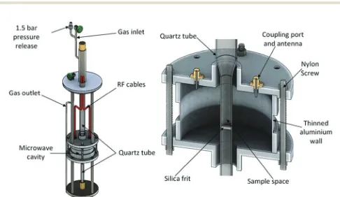
sample environment rig, shown in Fig. 1, which was placed in the vacuum chamber of POLARIS. The powdered sample was supported by a gas-permeable silica frit within a quartz tube which passed through the centre of the MCR such that the powder sample filled the quartz tube within the cavity where it intersected with the incident neutron beam. Argon and ammonia gasses are passed through the quartz tube and sample. The quartz tube was thin walled, with an outer radius of 6 mm, had very low dielectric loss and provided only a small contribu-tion to neutron diffraccontribu-tion background. The cylindrical MCR was milled out of aluminium with internal cavity dimensions of 46 mm radius with 65 mm height, with 10.5 mm radius holes in the top and bottom to allow access for the quartz sample tube and with microwave chokes surrounding these holes to mini-mise radiative losses. A 20 mm high section of the cavity wall was milled down to a thickness of 1 mm to allow the neutron beam to pass through with minimal scattering from the cavity. Nylon bolts were used in the construction of the cavity to reduce coherent neutron scattering from the cavity structure along the path of the neutron beam. The cavity was excited using panel mounted SMA connector jacks with extended centre conductor providing capacitive coupling to the electric field.
Fig. 1 Schematic diagram of the experimental housing for the MCR in the POLARIS neutron diffractometer (left) and the MCR alone, showing internal position of components (right).9
Open Access Article. Published on 04 April 2018. Downloaded on 15/05/2018 12:13:31.
This article is licensed under a
[image:2.595.306.549.539.680.2]The internal dimensions of the cavity were selected so the cavity could be excited in the TM010mode at 2.5 GHz. These
dimensions also prevent interference from other modes and ensure a highQ. The TM010mode was chosen as it provides a
high electric field along the axis of the cavity and very low magnetic field at the same point, which sensitises the measure-ments to the electric properties of the material. The sample tube was aligned parallel with the electric field to minimise depolarisation effects. The use of the TM010mode ensured an
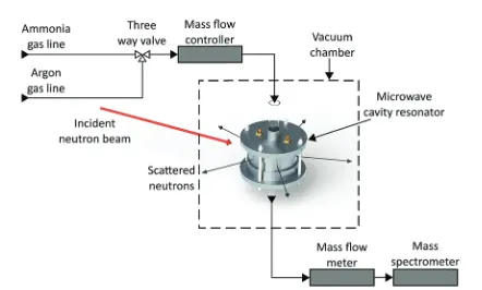
almost uniform electric field throughout the sample area. The gas supply was regulated by a custom-built gas panel. Outgasses were measured by a mass flow meter (Chell CCD100) before passing into a mass spectrometer (HPR-20 QIC R&D Plus from Hiden Analytical). This mass spectrometer was used to monitor deuterated ammonia (ND3), hydrogen, deuterium, argon,
nitrogen, oxygen and water (Fig. 2). All measurements were taken at room temperature and pressure.
The MCR was connectedviathe SMA connectors and radio frequency (RF) cables to a FieldFox N9912A vector network analyser (VNA). The power transmission coefficient |S21|2was
measured in the frequency domain and non-linear, least-squares curve fitting to a Lorentzian response was used to determine resonant frequencies,Qfactors and resonant bandwidths. Micro-wave data were recorded every 6 seconds. Neutron diffraction data were collected at the fastest possible rate (2 minute intervals) in order to capture reaction dynamics. Due to the relatively slow rate of neutron diffraction data collection, the flow rate of gasses was set to be very low (5 cm3min1) so that all the structural changes induced by gas absorption could be captured.
Synthesis
[Zr6O4(OH)4(4,40-biphenyldicarboxylate)6] (UiO-67). ZrCl4
(1.049 g, 4.5 mmol, 1 eq.), biphenyl-4,40-dicarboxylic acid (1.090 g, 4.5 mmol, 1 eq.) andL-proline (2.590 g, 22.5 mmol, 5 eq.) were added
to a 250 ml glass jar. 100 ml ofN,N-dimethylformamide (DMF) was added, followed by concentrated HCl (0.4 ml, 1 eq.). The reaction mixture was sonicated for several minutes until a homogeneous white suspension remained then placed in the oven at 1201C
for 24 hours. After this period the jar was removed and allowed to cool to room temperature. The product was collected by
centrifugation, washing once with fresh DMF (30 ml) and three times with methanol (3 30 ml). After drying in a vacuum desiccator, the product was added to a 250 ml glass jar and immersed in tetrahydrofuran (THF, 100 ml). The product was dispersed by stirring then placed in the oven at 501C overnight.
After this period the THF was replaced with fresh THF and the process was repeated three times then the product was dried under vacuum. The powder X-ray diffraction pattern matched that of the literature,49 indicating phase purity. An N2 adsorption
isotherm collected at 77 K gave a BET surface area of 2465 m2g1.
[Cu3(1,3,5-benzenetricarboxylate)2] (HKUST-1).
1,3,5-Benzene-tricarboxylic acid (6.657 g, 31.7 mmol, 1 eq.) and Cu(NO3)2
2.5H2O (11.136 g, 47.90 mmol, 1.5 eq.) were each dissolved in
a 1 : 1 : 1 mixture of DMF, ethanol and water (750 ml) by sonica-tion. A portion of each reagent solution (50 ml) was then added to 250 ml glass jars (total reaction volume = 100 ml). The resulting solutions were briefly mixed by stirring and then placed in an oven at 701C for 24 hours. After this period the
jars were removed and allowed to cool to room temperature. The contents of the jars were collected by filtration, added to a 250 ml glass jar and immersed in ethanol (100 ml). The product was dispersed by stirring and once settled the ethanol was replaced with DMF. This process was repeated a further three times, the DMF replaced by acetone which was subsequently replaced with fresh acetone then the product was collected by filtration. The product was dried in a vacuum desiccator. The powder X-ray diffraction pattern matched that of the literature,50 indicating phase purity. An N2adsorption isotherm collected at 77 K gave a
BET surface area of 1825 m2g1.
[Co(2,5-dioxybenzenedicarboxylate)] (CPO-27-Co).
2,5-Dihydroxy-terephthalic acid (2.675 g, 13.5 mmol, 1 eq.) and Co(NO3)26H2O
(13.359 g, 45.9 mmol, 3.4 eq.) were each dissolved in a 1 : 1 : 1 mixture of DMF, ethanol and water (562.5 ml) by sonication. A portion of each reagent solution (62.5 ml) was then added to 250 ml glass jars (total reaction volume = 125 ml). The resulting solutions were briefly mixed by stirring and then placed in an oven at 100 1C for 24 hours. After this period the jars were
removed and allowed to cool to room temperature. The con-tents of the jars were collected by filtration, added to a 250 ml glass jar and immersed in methanol (100 ml). The product was dispersed by stirring and once settled the methanol was replaced with fresh methanol and this process was repeated three times before the product was collected by filtration. The MOF was placed under vacuum overnight in a vacuum desiccator then activated by heating at 1201C under vacuum.
The powder X-ray diffraction pattern matched that of the literature,51indicating phase purity. An N2adsorption isotherm
collected at 77 K gave a BET surface area of 1300 m2g1.
Results
As ammonia is absorbed by a sample there is expected to be a considerable change in both resonant frequency and bandwidth. Absorption of ammonia by the host material, both physisorbed to the surface and coordinated within the material,
Fig. 2 Schematic diagram of the simultaneous neutron diffraction and microwave measurement setup, showing neutron beam, gas lines and measurement apparatus.
Open Access Article. Published on 04 April 2018. Downloaded on 15/05/2018 12:13:31.
This article is licensed under a
[image:3.595.57.278.550.683.2]causes a drop in the resonant frequency due to the polar nature of ammonia. The bandwidth of the system increases during the absorption of ammonia due to its associated dielectric loss. This response is consistent with absorption of a polar sample with associated dielectric loss into a solid-state sample.52
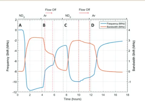
Dielectric properties of UiO-67
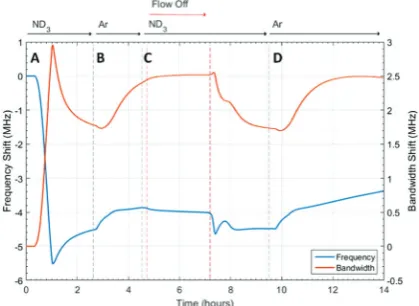
The microwave dielectric properties of UiO-67 are shown in Fig. 3. As with all samples, we plot changes in resonant frequency and bandwidth, as these are proportional to changes in the real and imaginary parts, respectively, of the complex permittivity (from eqn (1) and (2)). No change in microwave dielectric properties were initially observed as there is a con-siderable time-lag between initiating ammonia flow and the gas reaching the sample. As the ammonia gas reaches UiO-67 an increase in resonant bandwidth and concomitant decrease in resonant frequency was observed. These changes in dielectric properties continued until the sample had been exposed to ammonia for about 2.2 h (section A, Fig. 3) at which point both the increase in bandwidth and decrease in frequency were observed to saturate, suggesting both strong (potentially chemi-sorptive) binding of ammonia alongside weaker physisorption. The presence of defects in UiO-67, which is well established for Zr MOFs,53,54 could account for any chemisorption through coordination of NH3 to unsaturated Zr4+ units. Alternatively,
ordered binding of water within UiO-67 has been observed crystallographically through hydrogen bonding with m4-OH
groups at the Zr6 secondary building units,55 and this strong
binding site would also be available to ammonia.
This behaviour was consistent with the saturation of the sample with ammonia, as was observed for previous studies.9,41 After dielectric saturation, ammonia flow was maintained and during this period the bandwidth remained approximately con-stant and the resonant frequency increased slightly. As changes in bandwidth are most closely associated with physisorbed ammonia9 and resonant frequency with chemisorbed (metal
bound) ammonia, these observations suggest a saturation of
the host surfaces with ammonia but a small amount of loss of ammonia from tightly bound sites. After about 4 h, the system was flushed with argon and then the gas flow interrupted to collect high resolution diffraction data (section B, Fig. 3). An immediate decrease in bandwidth and increase in frequency were observed under argon flow, which were consistent with the loss of ammonia with a low isostatic binding energy. After approximately 5.5 h (section B, Fig. 3) argon flow was reintro-duced to the sample and a change in dielectric properties consistent with the further loss of ammonia from the sample were observed. After this second ammonia desorption both the frequency and bandwidth largely returned their original values, although a significant frequency shift was still observed. This suggests that some tightly bound ammonia (influencing the sample polarization to a greater degree than its dielectric loss) was retained within the UiO-67 sample. While the data presented may be considered to be indicative of a two-step ammonia desorption, the plateau in dielectric properties formed after the first ammonia loss arises solely due to the isolation of the sample from gas flow. Consequently, all the changes in dielectric properties observed in section B of Fig. 3 arose as a result of a single ammonia desorption process. It is interesting to note that the rate of change of frequency was approximately twice that of bandwidth which again is indica-tive of a loss of weakly bound, physisorbed, ammonia as observed in previous studies.9,41 The ammonia absorption process was repeated in section C with similar results, except that when the sample was held under static ammonia (around 10.5 h to 12.5 h) the changes in dielectric properties (decrease in bandwidth, increase in frequency) were smaller than when the sample was held under static argon, which is consistent with the dielectric properties arising from the natural loss of ammonia due to equilibrium processes. In the final stage (section D) ammonia is lost under argon flow and it is apparent that the bandwidth recovers to only very slightly less than its original value. The resonant frequency, however, still demon-strates a significant negative shift, consistent with the produc-tion of a more polar material as described above.
Structural properties of UiO-67
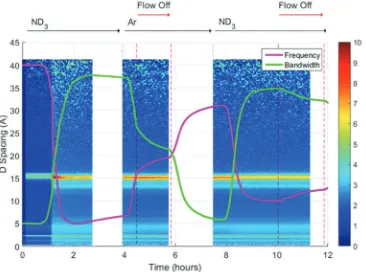
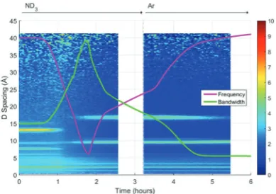
A surface plot of the Bragg diffraction from bank 1 for the absorption and desorption of ammonia (ND3) by UiO-67 is
shown in Fig. 4. The gaps in the Bragg information correspond to interruptions in time resolved data collection. These data may be used to help us understand the ammonia absorption and desorption processes observed in UiO-67. As the ammonia flow reaches the sample (around 1 h) new Bragg peaks corres-ponding to a structural modification induced by ordered ammonia binding were observed. In section B, the sample has been flushed with argon gas and the sample isolated from the flow. Here, the Bragg peaks corresponding to the new ammonia-containing superstructure remain at approximately constant intensity, indicating that ammonia molecules remained tightly bound within the structure, which was consistent with the dielectric data discussed above. Once the ammonia flow is resumed, the Bragg peaks for the ammonia coordinated
Fig. 3 Frequency shift (MHz) and bandwidth shift (MHz) for ammonia absorption and desorption in UiO-67 under ammonia (ND3) and argon (Ar)
flows. Where A is the first ammonia flow, B is the system flushed with argon, C is the second ammonia flow and D is the second flush with argon.
Open Access Article. Published on 04 April 2018. Downloaded on 15/05/2018 12:13:31.
This article is licensed under a
[image:4.595.50.290.505.672.2]UiO-67 material decrease in intensity, suggesting that the ammonia flow degraded the ammonia-coordinated UiO-67 sample somewhat, although a significant portion of the mate-rial remained crystalline. The strengthening and weakening of the intensity of the Bragg peaks on exposure to ammonia or flushing with argon suggests that further structural changes are being induced in the MOF host beyond the superstructure observed on first exposure to ammonia, although further detailed structural analyses would have to be performed to fully identify these. The final sample polarisation, as indicated by the change in resonance frequency, was lower than that of the original sample, whereas a final bandwidth shift of approximately zero was recorded. These observations are consistent with both the presence of a strongly ammonia-coordinated material or more polar decomposition product. Analysis of neutron diffraction and
ex situX-ray diffraction studies performed on the material after this experiment (see Fig. S1, ESI†) failed to identify any impurity phases. While the lack of crystalline impurities is reassuring, decomposition products may not be crystalline and therefore not appear in these investigations. However, where amorphous materials are produced through the action of ammonia we might expect to see an increase in the background for these data sets, which was not observed for both the neutron and X-ray diffraction. Consequently, we conclude that UiO-67 is able to reversibly bind and release ammonia at room temperature and pressure without significant degradation and that some tightly bound ammonia remains within the MOF even after flushing with argon gas.
If we overlay the dielectric properties on the Bragg surface plot (Fig. 5) we note a high degree of correlation between the Bragg diffraction intensity of the ammonia bound phase and the dielectric properties. In particular between 4 and 6 h when the sample was not under gas flow, the frequency and bandwidth both tend to fixed values with the intensity of the main Bragg peak (15 Å) remaining at constant intensity.
When ammonia is passed over the sample again (8–11 h) the Bragg intensity of the new phase decreases noticeably as the frequency shift decreases and bandwidth increases, all of which are consistent with the uptake of ammonia as seen previously.
Dielectric properties of HKUST-1
The changes in dielectric properties of HKUST-1 on exposure to ammonia are shown in Fig. 6. Again, a decrease in frequency and increase in bandwidth were observed on ammonia absorp-tion. The initial dielectric behaviour for HKUST-1 was similar to that observed for UiO-67 and was consistent with the absorp-tion of ammonia. After approximately 1.8 h this behaviour reversed, with a decrease in bandwidth and increase in frequency observed at approximately the same rate, but opposite sign, as the original behaviour and consistent with the loss of ammonia. A further change to a slower rate of change was then observed at approximately 2.2 h. At 3.5 h, the ammonia flow was replaced with argon and the rate of decrease in bandwidth and increase in frequency were observed to increase, approaching saturation after approximately 5 h at a frequency approximately equal to the starting value, but at a much lower bandwidth. The point of inflection and fundamental changes in dielectric properties
Fig. 4 A surface plot of Bragg diffraction collected from bank 1 of POLARIS during ammonia absorption and desorption within UiO-67 under ammonia (ND3) and argon (Ar) flows. The intensity of the Bragg lines is
represented by the colour scale on the right. The white spaces represent the periods when time resolved data collection was stopped to collect high resolution diffraction data. Where A is the first ammonia flow, B is the system flushed with argon and C is the second ammonia flow.
Fig. 5 Superimposition of the surface plot of Bragg diffraction and dielectric data during ammonia absorption and desorption within UiO-67 under ammonia (ND3) and argon (Ar) flows.
Fig. 6 Frequency shift (MHz) and bandwidth shift (MHz) for ammonia absorption and desorption in HKUST-1 under ammonia (ND3) and argon
(Ar) flows. Where A is the first ammonia flow and B is the system flushed with argon.
Open Access Article. Published on 04 April 2018. Downloaded on 15/05/2018 12:13:31.
This article is licensed under a
[image:5.595.67.269.49.198.2] [image:5.595.338.521.50.186.2] [image:5.595.308.544.515.671.2]observed after 1.8 h was consistent with a structural change in the host MOF material, potentially mirroring the decomposition observed by other groups.24,25
Structural properties of HKUST-1
A surface plot of the Bragg diffraction from the absorption and desorption of ammonia (ND3) by HKUST-1 is shown in Fig. 7.
The Bragg peaks observed at the beginning of the experiment were consistent with the structure of HKUST-1. A clear struc-tural transformation from the original HKUST-1 structure to a new phase or phases was observed as the ammonia reaches the sample (1 h). It is interesting to note that there are two small points of inflection in the bandwidth shift at approximately 1.4 and 1.6 h that hint at complex behaviour within this structural transformation. After 1.8 h the new phase had become the dominant phase and it is therefore likely that this transforma-tion was the origin of the change in dielectric properties observed in Fig. 6. On exposure to argon gas, some of the Bragg peaks of this new phase or phases weaken in intensity and broaden in resolution where others remain strong. As argon flow is thought to remove weakly bound ammonia molecules, the change in intensity of these Bragg peaks is strongly indica-tive of the presence of multiple phases, some associated with ammonia and others not. While we were not able to identify the composition of these impurity materials from these neutron diffraction and ex situ X-ray diffraction (see Fig. S2, ESI†) studies we conclude that exposure to ammonia causes the degradation of HKUST-1 during the experiment.
Initially ammonia is absorbed by HKUST-1, resulting in the expected increase in bandwidth and decrease in frequency shift. At some ammonia coverage of the surface of HKUST-1, decomposition occurs, perhaps due to dissolution of cations within a coordinated network of ammonia molecules, resulting in the production of materials with vastly differing dielectric properties. This is clearly seen within the diffraction data, where a clear phase transformation to a poorly crystalline
(as evidenced by broad Bragg peaks) new phase or phases was observed. If we superimpose the dielectric and structural data (Fig. 8) we can clearly see the first inflection point in the bandwidth data (around 1.4 h) occurs at or close to the onset of phase change, with the decrease in bandwidth occurring as this phase becomes dominant. The subsequent decrease in gradient for the rate of change of dielectric properties at approximately 2.2 h is less easily explained. However, close inspection of the diffraction data identifies a number of Bragg peaks that appear and disappear throughout the duration of the experiment, and this change in gradient appears to be coincidental with the appearance of a Bragg peak at approxi-mately 10 Å, suggestive of complex phase change behaviour. On exposure to argon flow, the poorly crystalline phase with its principle peaks at approximately 18 Å begins to disappear (from 2.5 to 5.5 h) with a concomitant decrease in bandwidth and increase in frequency shift.
Dielectric properties of CPO-27-Co
The changes in dielectric properties of CPO-27-Co on exposure to ammonia are shown in Fig. 9. A sudden decrease in frequency and increase in bandwidth were observed on ammonia absorp-tion. The initial dielectric behaviour for CPO-27-Co was similar to that observed for UiO-67 and HKUST-1, and again was consistent with the absorption of ammonia. After approximately 1.5 h this behaviour was reversed, with a slower decrease in bandwidth and increase in frequency observed, consistent with the loss of ammonia. A trend towards saturated dielectric properties was observed after approximately 2 h. It was interesting to note that the saturated value of the frequency and bandwidth were signifi-cantly different from the original values recorded for CPO-27-Co. After approximately 3 h the ammonia flow was replaced with argon. On removal of the ammonia flow, the frequency and bandwidth values were observed to increase, again saturating at approximately 5 h. Due to experimental difficulties the argon flow was replaced at this time with ammonia and then the flow arrested (between 5 h and 7 h), with no noticeable change in dielectric properties observed. When the ammonia flow was restarted (at around 7 h) an immediate decrease in frequency and bandwidth were observed, with a general decrease in
Fig. 7 A surface plot of Bragg diffraction collected from bank 1 of POLARIS during ammonia absorption and desorption within HKUST-1 under ammonia (ND3) and argon (Ar) flows. The intensity of the Bragg
lines is represented by the colour scale on the right. The white spaces represent the periods when time resolved data collection was stopped to collect high resolution diffraction data. Where A is the first ammonia flow and B is the system flushed with argon.
Fig. 8 Superimposition of the surface plot of Bragg diffraction and dielectric data during ammonia absorption and desorption within HKUST-1 under ammonia (ND3) and argon (Ar) flows.
Open Access Article. Published on 04 April 2018. Downloaded on 15/05/2018 12:13:31.
This article is licensed under a
[image:6.595.331.526.49.186.2] [image:6.595.68.268.49.188.2]bandwidth and approximately stable frequency subsequently observed during exposure to ammonia, although the behaviour was not monotonic. On replacing the ammonia flow with argon (at around 9.5 h) the bandwidth was observed to return to its original value whereas the frequency rose linearly until the completion of the experiment.
Examination of the dielectric properties of CPO-27-Co initi-ally suggested the presence of a structural transition or decom-position reaction. However, inspection of the diffraction data indicates no new Bragg peaks and therefore no change in the CPO-27-Co structure. The observed initial rise and then relaxa-tion of frequency and bandwidth shift is therefore anomalous and not easily explained. The subsequent behaviour of material under argon and ammonia flow was inconsistent with our understanding of how ammonia interacts with solids, with the addition of ammonia causing a decrease in bandwidth and relatively small, but complex, changes in frequency. We have previously observed9,41 that when ammonia binds to a solid it produces a decrease in the resonant frequency, due to increased polarisation of the sample, and an increase in the bandwidth due to greater dielectric loss. Here, the behaviour seems to be the opposite and indicates that, after its initial exposure to ammonia and flushing with argon, exposure to ammonia causes CPO-27-Co to reduce the amount of weakly bound ammonia (associated with increases in bandwidth) whilst very slightly increasing the amount of more strongly bound ammonia (associated with decreases in frequency).
Structural properties of CPO-27-Co
A surface plot of the Bragg diffraction from the absorption and desorption of ammonia (ND3) by CPO-27-Co is shown in Fig. 10.
The Bragg peaks observed at the beginning of the experiment were consistent with the structure of CPO-27-Co. It is interesting to note that there appears to be no clear structural transformation in the sample during ammonia absorption and desorption, which may be unexpected given the variety of dielectric properties observed, but likely corresponds to retention of the framework
structure upon binding of ammonia. Binding of gases by CPO-27 derivatives usually occurs through chemisorption at open metal sites followed by physisorption within the pores. While all the Bragg peaks are relatively weak (the Bragg peak at 2.5 Å is due to diffraction from the sample environment) there does appear to be a change in the intensity of the Bragg peaks arising from CPO-27-Co, although there is a general variation in scattering intensity across all the data (as evidenced by the variation in background intensity) and therefore it is difficult to derive much useful information from these data. Similar results were obtained fromex situX-ray diffrac-tion studies (see Fig. S3, ESI†).
Conclusions
HKUST-1 was observed to decompose after only 1 h exposure to ammonia, although it was not possible to identify the decom-position products of this interaction. This decomdecom-position may explain the unusual dielectric properties demonstrated by the HKUST-1 material. It can be seen from Fig. 6 and 7 that HKUST-1 undergoes a complex interaction with ammonia, producing a number of new phases as a function of exposure time and that, due to the dynamic decomposition process evidenced here, the displayed dielectric properties must be considered as composites of many phases and therefore does not warrant further description.
For CPO-27-Co, the dielectric properties presented in Fig. 9 initially suggested the presence of a structural transition or decomposition reaction whereas the diffraction data (Fig. 10) indicated no new Bragg peaks and therefore no change in the CPO-27-Co structure. The observed initial rise and then relaxation of frequency and bandwidth shift is therefore anomalous with our understanding of how ammonia interacts with solid materials.
Such behaviour is difficult to interpret, but it may be that on exposure to additional ammonia, the weakly bound ammonia
Fig. 9 Frequency shift (MHz) and bandwidth shift (MHz) for ammonia absorption and desorption in CPO-27-Co under ammonia (ND3) and argon
[image:7.595.62.272.51.204.2](Ar) flows. Where A is the first ammonia flow, B is the system flushed with argon, C is the second ammonia flow and D is the second flush with argon.
Fig. 10 A surface plot of Bragg diffraction collected from bank 1 of POLARIS during ammonia absorption and desorption within CPO-27-Co under ammonia (ND3) and argon (Ar) flows. The intensity of the Bragg lines
is represented by the colour scale on the right. The white spaces represent the periods when time resolved data collection was stopped to collect high resolution diffraction data. Where A is the first ammonia flow, B is the system flushed with argon, C is the second ammonia flow and D is the second flush with argon.
Open Access Article. Published on 04 April 2018. Downloaded on 15/05/2018 12:13:31.
This article is licensed under a
[image:7.595.328.530.53.197.2]begins to form coordinated (hydrogen bonded) networks, which have been seen in other MOFs,56 where the hydrogen-bonded ammonia molecules have fewer degrees of freedom than weakly absorbed individual molecules and therefore con-tribute less to dielectric loss. Analogous ordered arrays of water can be observed crystallographically in hydrated CPO-27-Co, with specific water molecules hard to remove presumably as a consequence of hydrogen bonding, although the MOF can be evacuated without structural change.57 Indeed, this may well explain the sharp rise and then relaxation of dielectric proper-ties observed on first exposure to ammonia. Consequently, when the ammonia flow is replaced with argon, ammonia is removed, disrupting the coordination networks, restoring their ability to contribute to increased bandwidth. Such networks might also affect the polarisation of the system, with multiple hydrogen bonded layers of ammonia acting to dampen polar-isation effects through charge delocalpolar-isation. In this case we would expect smaller overall changes to sample polarisation with respect to dielectric loss, and this is indeed what we observe. On final exposure to argon, the polarisation is seen to increase linearly, which again is consistent with the removal of charge delocalising networks within CPO-27-Co. While further studies are required to confirm the presence of coordi-nated ammonia networks and to validate this hypothesis, these conclusions are consistent with the observed data and, if confirmed, highlight the ability of CPO-27-Co to stably store considerable quantities of ammonia.
For UiO-67, formation of a superstructure is observed on ammonia absorption, with dielectric properties that follow those expected for the absorption and desorption of ammonia without decomposition. It should also be noted that the band-width shift returns to zero whereas the frequency shift does not regain its full value, which is indicative of the retention of ammonia within the material and therefore of a more stably bound ammonia species, hypothesised to be either coordinated to metals at defect sites or strongly hydrogen bonded at the metal cluster.
The combined methodology of diffraction and dielectric spectroscopy provides a valuable tool to interpret complex ammonia absorption and desorption behaviour, providing insights not available from the use of these techniques indivi-dually. Having previously demonstrated its utility in examining simple molecular species such as metal salts,9,41we have now shown that it is equally applicable to study much more complex materials such as MOFs, and that the methodology provides information on subtle adsorption processes and structural features that may be missed by other techniques applied individually. The MOF materials investigated show a variety of properties, ranging from decomposition, through structural modification to structural inviolability, with the potential for ammonia filtering and/or storage highlighted for the UiO-67 and CPO-27-Co materials, which show strong binding and significant uptake. Furthermore, an understanding of the interaction of these materials with ammonia provides signifi-cant insight that may be used to design a new generation of materials with enhanced resistance to and greater binding enthalpies for ammonia.
Conflicts of interest
There are no conflicts to declare.
Acknowledgements
Thanks to EPSRC for funding Michael Barter and to STFC ISIS Neutron and Muon Spallation facility for funding Michael Barter and for funding this research. RSF thanks the Royal Society for receipt of a University Research Fellowship, and the University of Glasgow for funding. Information on the data underpinning the results presented here, including how to access them, can be found in the Cardiff University data catalogue at http://doi.org/10.17035/d.2018.0046822874.
References
1 A. Klerke, C. H. Christensen, J. K. Nørskov and T. Vegge, Ammonia for hydrogen storage: challenges and opportu-nities,J. Mater. Chem., 2008,18, 2304.
2 R. Lan, J. T. S. Irvine and S. Tao, Ammonia and related chemicals as potential indirect hydrogen storage materials,
Int. J. Hydrogen Energy, 2012,37, 1482–1494.
3 C. H. Christensen, T. Johannessen, R. Z. Sørensen and J. K. Nørskov, Towards an ammonia-mediated hydrogen economy?,Catal. Today, 2006,111, 140–144.
4 S. Niaz, T. Manzoor and A. H. Pandith, Hydrogen storage: Materials, methods and perspectives,Renewable Sustainable Energy Rev., 2015,50, 457–469.
5 W. I. F. David, J. W. Makepeace, S. K. Callear, H. M. A. Hunter, J. D. Taylor and T. J. Wood,et al., Hydrogen Production from Ammonia Using Sodium Amide,J. Am. Chem. Soc., 2014,136, 13082–13085.
6 G. Thomas and G. Parks, Potential Roles of Ammonia in a Hydrogen Economy,Energy, 2006, 1–23.
7 C. H. Christensen, R. Z. Sørensen, T. Johannessen, U. J. Quaade, K. Honkala and T. D. Elmøe,et al., Metal ammine complexes for hydrogen storage, J. Mater. Chem., 2005,15, 4106–4108.
8 R. Z. Sørensen, J. S. Hummelshøj, A. Klerke, J. B. Reves, T. Vegge and J. K. Nørskov,et al., Indirect, reversible high-density hydrogen storage in compact metal ammine salts,
J. Am. Chem. Soc., 2008,130, 8660–8668.
9 M. O. Jones, J. Hartley and A. Porch, Simultaneous neutron diffraction and microwave dielectric characterisation of ammine materials – a non-destructive, non-contact charac-terisation tool for determining ammonia content in solids,
Phys. Chem. Chem. Phys., 2016,18, 23340–23347.
10 A. Zu¨ttel, P. Wenger, S. Rentsch, P. Sudan, P. Mauron and C. Emmenegger, LiBH4 a new hydrogen storage material, J. Power Sources, 2003,118, 1–7.
11 F. Schu¨th, B. Bogdanovic´ and M. Felderhoff, Light metal hydrides and complex hydrides for hydrogen storage,Chem. Commun., 2004, 2249–2258.
12 J. R. Long and O. M. Yaghi, The pervasive chemistry of metal-organic frameworks,Chem. Soc. Rev., 2009,38, 1213–1214.
Open Access Article. Published on 04 April 2018. Downloaded on 15/05/2018 12:13:31.
This article is licensed under a
13 H. C. Zhou, J. R. Long and O. M. Yaghi, Introduction to metal-organic frameworks,Chem. Rev., 2012,112, 673–674. 14 H. Furukawa, K. E. Cordova, M. O’Keeffe and O. M. Yaghi, The chemistry and applications of metal-organic frame-works,Science, 2013,341, 1230444.
15 K. Sumida, D. L. Rogow, J. A. Mason, T. M. McDonald, E. D. Bloch and Z. R. Herm,et al., Carbon dioxide capture in metal-organic frameworks, Chem. Rev., 2012, 112, 724–781.
16 Y. S. Bae and R. Q. Snurr, Development and evaluation of porous materials for carbon dioxide separation and capture,
Angew. Chem., Int. Ed., 2011,50, 11586–11596.
17 M. P. Suh, H. J. Park, T. K. Prasad and D.-W. Lim, Hydrogen storage in metal-organic frameworks,Chem. Rev., 2011,112, 782–835.
18 J. Sculley, D. Yuan and H.-C. Zhou, The current status of hydrogen storage in metal-organic frameworks-updated,
Energy Environ. Sci., 2011,4, 2721.
19 Y. He, W. Zhou, G. Qian and B. Chen, Methane storage in metal-organic frameworks,Chem. Soc. Rev., 2014,43, 5657–5678. 20 D. Britt, D. Tranchemontagne and O. M. Yaghi,
Metal-organic frameworks with high capacity and selectivity for harmful gases, Proc. Natl. Acad. Sci. U. S. A., 2008, 105, 11623–11627.
21 D. Saha and S. Deng, Ammonia adsorption and its effects on framework stability of MOF-5 and MOF-177,J. Colloid Interface Sci., 2010,348, 615–620.
22 I. Spanopoulos, P. Xydias, C. D. Malliakas and P. N. Trikalitis, A Straight Forward Route for the Development of Metal– Organic Frameworks Functionalized with Aromatic OH Groups: Synthesis, Characterization, and Gas (N2, Ar, H2,
CO2, CH4, NH3) Sorption Properties, Inorg. Chem., 2013, 52,
855–862.
23 N. B. Shustova, A. F. Cozzolino, S. Reineke, M. Baldo and M. Dinca, Selective Turn-On Ammonia Sensing Enabled by High-Temperature Fluorescence in Metal–Organic Frame-works with Open Metal Sites,J. Am. Chem. Soc., 2013,135, 13326–13329.
24 G. W. Peterson, G. W. Wagner, A. Balboa, J. Mahle, T. Sewell and C. J. Karwacki, Ammonia Vapor Removal by Cu3(BTC)2
and Its Characterization by MAS NMR, J. Phys. Chem. C, 2009,113, 13906–13917.
25 E. Borfecchia, S. Maurelli, D. Gianolio, E. Groppo, M. Chiesa and F. Bonino,et al., Insights into adsorption of NH3 on
HKUST-1 metal-organic framework: A multitechnique approach,J. Phys. Chem. C, 2012,116, 19839–19850. 26 C. Petit and T. J. Bandosz, MOF-graphite oxide composites:
Combining the uniqueness of graphene layers and metal-organic frameworks,Adv. Mater., 2009,21, 4753–4757. 27 C. Petit and T. J. Bandosz, Graphite Oxide/Polyoxometalate
nanocomposites as adsorbents of ammonia, J. Phys. Chem. C, 2009,113, 3800–3809.
28 C. Petit and T. J. Bandosz, Enhanced adsorption of ammo-nia on metal-organic framework/graphite oxide composites: Analysis of surface interactions,Adv. Funct. Mater., 2010,20, 111–118.
29 C. Petit, B. Mendoza and T. J. Bandosz, Reactive adsorption of ammonia on Cu-based MOF/graphene composites,Langmuir, 2010,26, 15302–15309.
30 C. Petit and T. J. Bandosz, Synthesis, characterization, and ammonia adsorption properties of mesoporous metal-organic framework (MIL(Fe))-graphite oxide composites: Exploring the limits of materials fabrication, Adv. Funct. Mater., 2011,21, 2108–2117.
31 C. Petit, L. Huang, J. Jagiello, J. Kenvin, K. E. Gubbins and T. J. Bandosz, Toward understanding reactive adsorption of ammonia on Cu-MOF/graphite oxide nanocomposites,
Langmuir, 2011,27, 13043–13051.
32 A. M. B. Furtado, J. Liu, Y. Wang and M. D. LeVan, Meso-porous silica–metal organic composite: synthesis, charac-terization, and ammonia adsorption,J. Mater. Chem., 2011,
21, 6698.
33 O. T. Wilcox, A. Fateeva, A. P. Katsoulidis, M. W. Smith, C. A. Stone and M. J. Rosseinsky, Acid loaded porphyrin-based metal–organic framework for ammonia uptake,
Chem. Commun., 2015,51, 14989–14991.
34 T. Kajiwara, M. Higuchi, D. Watanabe, H. Higashimura, T. Yamada and H. Kitagawa, A systematic study on the stability of porous coordination polymers against ammonia,
Chem. – Eur. J., 2014,20, 15611–15617.
35 T. Grant Glover, G. W. Peterson, B. J. Schindler, D. Britt and O. Yaghi, MOF-74 building unit has a direct impact on toxic gas adsorption,Chem. Eng. Sci., 2011,66, 163–170. 36 M. J. Katz, A. J. Howarth, P. Z. Moghadam, J. B. DeCoste,
R. Q. Snurr and J. T. Hupp,et al., High volumetric uptake of ammonia using Cu-MOF-74/Cu-CPO-27, Dalton Trans., 2016,45, 4150–4153.
37 H. Jasuja, G. W. Peterson, J. B. Decoste, M. A. Browe and K. S. Walton, Evaluation of MOFs for air purification and air quality control applications: Ammonia removal from air,
Chem. Eng. Sci., 2015,124, 118–124.
38 S. Hindocha and S. Poulston, Study of the scale-up, formu-lation, ageing and ammonia adsorption capacity of MIL-100(Fe), Cu-BTC and CPO-27(Ni) for use in respiratory protection filters,Faraday Discuss., 2017,201, 113–125. 39 Y. Chen, F. Zhang, Y. Wang, C. Yang, J. Yang and J. Li,
Recyclable ammonia uptake of a MIL series of metal-organic frameworks with high structural stability,Microporous Meso-porous Mater., 2018,258, 170–177.
40 A. J. Rieth, Y. Tulchinsky and M. Dinc, High and Reversible Ammonia Uptake in Mesoporous Azolate Metal-Organic Frameworks with Open Mn, Co, and Ni Sites,J. Am. Chem. Soc., 2016,138, 9401–9404.
41 J. Hartley, A. Porch and M. Jones, A non-invasive microwave method for assessing solid-state ammonia storage, Sens. Actuators, B, 2015,210, 726–730.
42 M. Dietrich, D. Rauch, U. Simon, A. Porch and R. Moos, Ammonia storage studies on H-ZSM-5 zeolites by microwave cavity perturbation: correlation of dielectric properties with ammonia storage,J. Sens. Sens. Syst., 2015,4, 263–269. 43 M. Dietrich, D. Rauch, A. Porch and R. Moos, A Laboratory
Test Setup for in situ Measurements of the Dielectric
Open Access Article. Published on 04 April 2018. Downloaded on 15/05/2018 12:13:31.
This article is licensed under a
Properties of Catalyst Powder Samples under Reaction Conditions by Microwave Cavity Perturbation: Set up and Initial Tests,Sensors, 2014,14, 16856–16868.
44 W. D. Kumler, The Dipole Moment of Ammonia in Solution,
J. Am. Chem. Soc., 1936,58, 1049–1050.
45 D. M. Pozar,Microwave Engineering, Wiley, 4th edn, 2011. 46 R. A. Waldron, Perturbation theory of resonant cavities,
Proc. IEE Part C Monogr., 1960,107, 272.
47 S. Hull, R. I. Smith, W. I. F. David, A. C. Hannon, J. Mayers and R. Cywinski, The Polaris powder diffractometer at ISIS,
Phys. B, 1992,180–181, 1000–1002.
48 R. I. Smith, S. Hull and A. R. Armstrong, The Polaris Powder Diffractometer at ISIS,Mater. Sci. Forum, 1994,166–169, 251–256. 49 R. J. Marshall, C. L. Hobday, C. F. Murphie, S. L. Griffin, C. A. Morrison and S. A. Moggach,et al., Amino acids as highly efficient modulators for single crystals of zirconium and hafnium metal–organic frameworks,J. Mater. Chem. A, 2016,4, 6955–6963.
50 X. Song, S. Jeong, D. Kim and M. S. Lah, Transmetalations in two metal–organic frameworks with different framework flexibilities: Kinetics and core–shell heterostructure,
CrystEngComm, 2012,14, 5753.
51 S. R. Caskey, A. G. Wong-Foy and A. J. Matzger, Dramatic Tuning of Carbon Dioxide UptakeviaMetal Substitution in
a Coordination Polymer with Cylindrical Pores,J. Am. Chem. Soc., 2008,130, 10870–10871.
52 D. Kim, A High Performance IBC-Hub Transceiver for Intra-Body Communication System, Microw. Opt. Technol. Lett., 2012,54, 2781–2784.
53 Z. Fang, B. Bueken, D. E. De Vos and R. A. Fischer, Defect-Engineered Metal-Organic Frameworks,Angew. Chem., Int. Ed., 2015,54, 7234–7254.
54 M. Taddei, When defects turn into virtues: The curious case of zirconium-based metal-organic frameworks, Coord. Chem. Rev., 2017,343, 1–24.
55 N. Ko, J. Hong, S. Sung, K. E. Cordova, H. J. Park and J. K. Yang,et al., A significant enhancement of water vapour uptake at low pressure by amine-functionalization of UiO-67,Dalton Trans., 2015,44, 2047–2051.
56 N. Nijem, K. Fu¨rsich, H. Bluhm, S. R. Leone and M. K. Gilles, Ammonia Adsorption and Co-adsorption with Water in HKUST-1: Spectroscopic Evidence for Cooperative Interactions,
J. Phys. Chem. C, 2015,119, 24781–24788.
57 P. D. C. Dietzel, R. E. Johnsen, R. Blom and H. Fjellvåg, Structural changes and coordinatively unsaturated metal atoms on dehydration of honeycomb analogous micro-porous metal-organic frameworks, Chem. – Eur. J., 2008,
14, 2389–2397.
Open Access Article. Published on 04 April 2018. Downloaded on 15/05/2018 12:13:31.
This article is licensed under a