1 DOI: 10.1002/((please add manuscript number)) Article type: Communication
Metal-organic framework-derived hybrid carbon nanocages as bifunctional electrocatalyst for oxygen reduction and evolution
Shaohong Liu,a, † Zhiyu Wang,a, † Si Zhou,b, † Fengjiao Yu,c Mengzhou Yu,a Chang-Yang
Chiang,c Wuzong Zhou,c Jijun Zhaob,* and Jieshan Qiua,*
Dr. S. H. Liu, Prof. Z. Y. Wang, Dr. S. Zhou, F. J. Yu, M. Z. Yu, C. Chiang, Prof. W. Z. Zhou, Prof. J. J. Zhao, Prof. J. S. Qiu
a State Key Lab of Fine Chemicals, Carbon Research Laboratory, Liaoning Key Lab for Energy Materials and Chemical Engineering, School of Chemical Engineering, Dalian University of Technology, Dalian 116024, China.
b Education Ministry Key Lab of Materials Modification by Laser, Ion and Electron Beams, Dalian University of Technology, Dalian 116024, China
c School of Chemistry, University of St Andrews, St Andrews, KY16 9ST, United Kingdom
†These authors contribute equally to this work.
E-mail: [email protected], [email protected]
Keywords: oxygen electrocatalysis, bifunctional electrocatalyst, metal-organic frameworks, hollow nanostructure, first-principles calculation
Abstract Oxygen reduction reaction (ORR) and oxygen evolution reaction (OER) is cornerstone reactions of many renewable energy technologies. Developing cheap yet durable
substitutes of precious metal catalysts, especially the bifunctional electrocatalysts with high
activity for both reactions and their streamlined coupling process, are highly desirable to reduce
the processing cost and complexity of renewable energy systems. Herein we report a facile
strategy for synthesizing double-shelled hybrid nanocages with outer shells of Co-N-doped
graphitic carbon (Co-NGC) and inner shells of N-doped microporous carbon (NC) by
templating against core-shelled metal-organic frameworks. The double-shelled NC@Co-NGC
nanocages well integrate the high activity of Co-NGC shells into robust NC hollow framework
with enhanced diffusion kinetics, exhibiting superior electrocatalytic properties to Pt and RuO2
as bifunctional electrocatalyst for ORR and OER and holding the promise as efficient air
electrode catalysts in Zn-air batteries. First-principles calculations revealed that high catalytic
2
between Co nanoparticles, the graphitic carbon and the doped N species. Strong yet favorable
adsorption of OOH* intermediate on high density of uncoordinated hollow-site C atoms with
respect to Co lattice in Co-NGC structure is a vital rate-determining step to achieve excellent
bifunctional electrocatalytic activity.
Oxygen reduction reaction (ORR) and oxygen evolution reaction (OER) are the cornerstone of many renewable energy storage and conversion technologies such as metal-air batteries, fuel cells and water electrolysis.[1-3] Both reactions, however, need highly active catalysts to achieve high efficiency since the oxygen electrode is a strongly irreversible system associated with high activation overpotential and sluggish kinetics. Noble metals (e.g., Pt) and their oxides (e.g., RuO2, IrO2) have been found to be the most active catalysts for electrocatalytic reduction and evolution of molecular oxygen. However, their large-scale application is greatly prohibited by high cost, supply scarcity and inferior durability.[4, 5] On the other hand, as the universal choice of ORR catalyst, the OER activity of Pt is limited by the in situ formation of insulating platinum oxides in the process. IrO2 and RuO2 are unstable at high potentials due to the in situ transformation to higher-valent oxides, in spite of the highest activity towards OER.[6] To fulfill the demands in practical use, the development of low-cost yet durable bifunctional electrocatalysts with high activity towards both ORR and OER process is highly desired to reduce the cost and complexity of the renewable energy storage and conversion systems.
3
sufficient localized reactive sites by modifying the charge distribution on carbon surface via the promoted electron transfer effect, which changes the local work function for O2 adsorption and consequently facilitate the ORR or OER.[12, 13] Very recently, the synergistic effect of metal@C nanoparticles and neighboring metal-Nx coordination sites has been demonstrated to promote the O2 adsorption by overlapping the highest occupied molecular orbital (HOMO) and lowest unoccupied molecular orbital (LUMO) of triplet O2 molecule during ORR.[14] Because of these combined effects, some exciting performance that is comparable or even superior to noble metal catalysts, has been achieved due to the enhanced reaction kinetics and structural stability in M-N-C electrocatalyst. Among available strategies, direct pyrolysis of metal-organic frameworks (MOFs) composed of atomically dispersed metal-containing clusters between organic linkers, represents one of the most efficient approaches for producing nanostructured M-N-C catalysts with uniformly distributed active sites, highly controlled dimensions and porosity.[15-19] However, only a handful of them show the capability of catalyzing more than one electrochemical reactions under appropriate conditions, especially for the reverse ORR/OER pair reactions.[20-24] To tackle these issues, one need to know how to design and fabricate high-performance ORR/OER electrocatalysts with multifunctional electrocatalytic activities, meanwhile, to understand the origin of their intrinsic activity and the catalytic reaction pathways involved in the process.
Since the electrocatalytic reduction and evolution of oxygen occurs at the
electrode-electrolyte-O2 triple-phase interface, engineering the nanoarchitecture of the M-N-C
electrocatalysts is critical to generate highly exposed active surface for fast exchange and
reaction of the reactants (e.g., O2, H+, OH- or H2O). Hollow nanostructures with low density,
very thin shells with a thickness below tens of nanometers and high permeability provide an
ideal framework for better controlling the local chemical micro-environment of the
electrocatalysts upon reaction. The formation of hollow cavity inside catalyst nanoparticle not
4
ensures fast diffusion of the reactant across the catalyst even if the aggregation occurs.[25, 26]
Macroscopically, it manifests as effective utilization of active mass due to high accessibility of
the inner pores to surrounding reactants. In the present work, we report the fabrication of
carbon-based hybrid double-shelled nanocages (DSNCs) derived from core-shelled zeolite
imidazole frameworks (ZIFs), a well-known subfamily of MOFs, as an active and stable
bifunctional electrocatalyst for both ORR and OER.[27] The hybrid nanocages feature with
closely packed double shells: a ZIF-8 derived inner shell of N-doped microporous carbon (NC)
and a ZIF-67 derived outer shell of Co-decorated N-doped mesoporous graphitic carbon
(Co-NGC), denoted as NC@Co-NGC DSNCs. In this kind of novel structure, the ZIF-67 derived
Co-NGC shells with stable structure and good conductivity is highly active to catalyze the
ORR/OER while the ZIF-8 derived NC act as the nanostructured hollow framework to facilitate
the diffusion kinetics.[28, 29] Their heterogeneous hybridization renders superior bifunctional
catalytic properties and durability to noble metal catalysts (e.g., Pt and RuO2) towards
ORR/OER and their coupled process, which are hardly attainable by the catalysts from single
MOF precursor. First-principles calculations have revealed that the Co-NGC shells owe their
highly catalytic activity to the charge transfer and redistribution between Co nanoparticles, the
graphitic carbon and the N dopants. This facilitates the favorable chemisorption of OOH*, the
rate-determining intermediate for ORR and OER, on uncoordinated C atoms on Co-NGC
surface, enabling the bifunctional electrocatalytic activity of NC@Co-NGC DSNC catalyst.
The potential and superior performance of NC@Co-NGC DSNC electrocatalyst are also
demonstrated in primary and rechargeable Zn-air batteries operated in air.
The synthetic strategy of NC@Co-NGC DSNCs is schematically illustrated in Figure 1.
Uniform polyhedral nanocrystals of ZIF-8 were first fabricated by the coordination of Zn2+ and
2-MeIm in methanol.[30] They function as the crystal seeds for subsequent epitaxial growth of
ZIF-67 with similar isoreticular structure ([M(MeIm)2] (M = Zn for ZIF-8 or Co for ZIF-67))
5
2-MeIm in methanol at room temperature. XRD analysis shows that the resultant
ZIF-8@ZIF-67 sample reasonably share similar feature with ZIF-8 and ZIF-ZIF-8@ZIF-67 crystals in peak intensity and
position (Figure S1a). The successful growth of ZIF-67 on ZIF-8 crystals can be visualized by
distinct color change from white to violet in the suspension after the seed-mediated growth (see
inset of Figure S1a). A panoramic view by filed-emission scanning electron microscopy
(FESEM) reveals that the sample consists of entirely uniform rhombic dodecahedrons with a
smooth surface and an average edge length of ca. 550 nm. The precisely controlled epitaxial
growth enables the ZIF-8@ZIF-67 crystals to inherit the polyhedral shape of ZIF-8 seeds that
are enclosed by twelve <110> facets (Figure S1b and Figure S2a). No aggregates or free
ZIF-67 particles are observed in the samples due to efficient deposition of ZIF-ZIF-67 on ZIF-8 crystals.
Transmission electron microscopy (TEM) characterization further confirms the formation of
polyhedral particles with high uniformity (Figure S1c). It should be noted that it is hard to
distinguish the interface between 67 shell and 8 core, as well as the thickness of
ZIF-67 shell due to their similar lattice structure. However, the formation of ZIF-8@ZIF-ZIF-67
core-shelled structure can be clearly visualized by elemental mapping, where the region of Zn
element is closely surrounded by that of Co element (Figure S1d). The presence of C and N
element is also detected in ZIF-8@ZIF-67 nanocrystals. The molar ratio of Zn to Co is 2.63 and
the N content can be as high as 29 at.%, confirmed by energy-dispersive X-ray (EDX) analysis
(FigureS3).
The core-shelled ZIF-8@ZIF-67 particles are then subjected to thermal annealing in flowing
N2 at 800 oC at a ramp rate of 2 oC min-1, followed by etching away the unstable Co
nanoparticles with H2SO4. Surprisingly, well-defined hollow nanocages instead of solid
nanoparticles commonly reported in literature up to now are created by the decomposition and
carbonization of ZIF-8@ZIF-67 crystals.[31] The FESEM analysis shows that the as-synthesized
samples have inherited the polyhedral shape of the parent ZIF-8@ZIF-67 crystals without
6
500-520 nm due to the shrinkage to denser carbon-based composites. The particles have a rough
surface anchored with numerous short carbon nanotubes (CNTs), as shown in Figure 2c. The
formation of CNTs is the result of the catalytic effect of Co nanoparticles on particle surface.[11]
FESEM image of a broken particle clearly indicates the presence of inner cavities underneath
the carbon shells (Figure 2c). The structure of closely packed double shells with uniform
thickness is visualized by TEM characterization (Figure 2d and e). The ZIF-8 derived inner
shells are composed of dense amorphous carbon with an average thickness of ca. 60 nm, which
are formed by the decomposition of ZIF-8 to ZnO/carbon composite and subsequent
carbothermal reduction to Zn/carbon composite, followed by the vaporization of Zn with the
temperature rise.[31] The ZIF-67-derived outer shells consist of relatively loose carbon with an
average thickness of ca. 40 nm, from which many short carbon nanotubes with a length of tens
of nanometers are extruded (Figure 2e and Figure S4). HRTEM analysis reveals the formation
of graphitic carbon structures decorated with Co nanoparticles enclosed in several graphitic
carbon layers, as a result of the catalytic graphitization of amorphous carbon by Co
nanoparticles of several nanometers at high temperature (Figure 2f).[16, 28, 32] The Co
nanoparticles in graphitic carbon sheath are very stable against acidic etching, which is desired
to enhance the electrocatalytic stability. By varying the size of ZIF-8 seeds employed, both the
size and interior volume of the nanocages could be rationally tailored. This is evidenced by the
fact that uniform NC@Co-NGC DSNCs with various edge lengths of ca. 150, 300 to 750 nm
can be fabricated by a similar approach except using ZIF-8 nanocrystals with different sizes as
the seeds ( Figure2g-i).
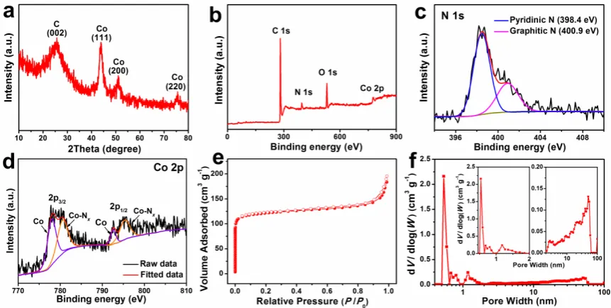
The structural characteristics of NC@Co-NGC DSNCs are identified by XRD analysis
(Figure 3a). The relatively sharp peak at 26° corresponds to (002) plane of graphitic carbon
while the others at around 44°, 51° and 76° is attributed to the diffraction from (111), (200) and
(220) planes of metallic Co (a = 3.545 Å, JCPDS No. 15-0806). FigureS5 shows the Raman
7
NC@Co-NGC and Co-NGC, the G bands at around 1589 cm-1 corresponds to the in-plane
vibration of sp2 carbon while the D band at around 1338 cm-1 mainly reflects the structural
defects in graphitic structure. The intensity ratio between them (ID/IG) is around 0.96, revealing
the domination of short-range order graphitic structure. Compared to NC, the G band of
NC@Co-NGC and Co-NGC is upshifted by 12 cm-1 in wavelength, suggesting strong electronic
interaction in them, possibly between carbon and metal atoms. Thermogravimetric analysis
(TGA) reveals that the content of metallic Co in NC@Co-NGC DSNCs is 16.8 wt.% (Figure
S6). The chemical composition and the effect of N doping are investigated by X-ray
photoelectron spectroscopy (XPS), revealing the presence of C, N, O and Co elements in
NC@Co-NGC DSNCs, where the N content is calculated to be 5.28 at.% (Figure 3b). The
high-resolution N 1s spectrum reveals the presence of two types of N species, namely, the
pyridinic N (ca. 398.4 eV) and graphitic N (ca. 400.9 eV) in the nanocages (Figure 3c). The
Co 2p XPS spectrum is resolved into two pairs of 2p3/2/2p1/2 doublets for metallic Co
(778.0/792.6 eV) and N-coordinated Co2+ (Co-N
x) (780.7/795.3 eV) with an energy separation
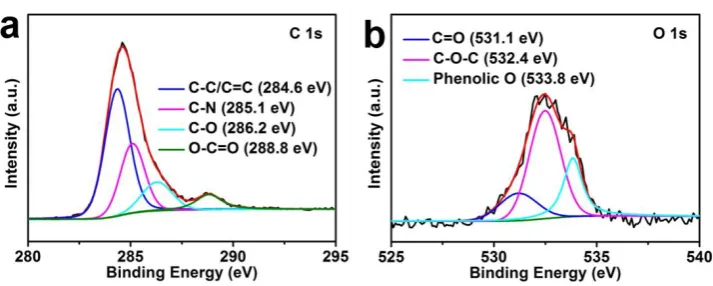
of 14.6 eV (Figure3d).[33, 34]The C1s XPS spectrum can be deconvoluted into the peaks for
sp2-hydridized carbon (284.6 eV), C-O bonds (286.5 eV) and O-C=O group (288.8 eV), as
shown in FigureS7a.[35] The identification of C-N bonds at 285.1 eV confirms the N doping in
NC@Co-NGC DSNCs.[35] The presence of O signal can be attributed to residual oxygen in
ZIF-derived carbon and the adsorbed oxygen from environmental atmosphere (Figure S7b). The N2
adsorption/desorption isotherms of NC@Co-NGC DSNCs are type-I isotherms (Figure 3e), in
which the isotherms with sharp increase in volume at low relative pressure indicate the presence
of micropores, mainly from ZIF-8 derived NC shells. The hysteresis loop at relative pressure
between 0.5-0.9 suggests the co-existence of mesopores from Co-decorated graphitic carbon
shell derived from ZIF-67. The pore size distribution indicates that the micropores are smaller
8
NC@Co-NGC DSNCs with unique hollow structure and hierarchical porosity has a
Brunauer-Emmett-Teller (BET) surface area of ca. 476 m2 g−1 and total pore volume of 0.303 m3 g−1.
The formation of double-shelled NC@Co-NGC nanocages is believed to be governed by a
surface-stabilized contraction process originated from the thermal stability difference of
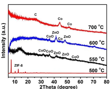
ZIF-67 and ZIF-8. TGA analysis reveals that ZIF-ZIF-67 is less stable than ZIF-8 (Figure S8), and would
decompose first to form rigid shells of CoO/carbon composite around ZIF-8 cores at above 500
oC (Figure S9a, e and Figure S10). Then, the rigid CoO/carbon shells could generate an
outward adhesive force at the interface between them and ZIF-8 cores, which suppress the
inward contraction of ZIF-8 due to the thermal-induced polycondensation. As a result, hollow
cavities are formed inside ZIF-8 cores as a balance of the mass loss (mainly the small molecules
such as NH3 and (CN)2) from ZIF-8 decomposition at evaluated temperature (e.g., 550 oC)
(Figure S9b and f).[36] At higher temperature (e.g., 600-700 oC), the CoO in outer shells is
reduced to metallic Co by surrounding carbonaceous species formed in situ to catalyze the
formation of graphitic carbon (Figure S9c, g and Figure S10). Eventually, double-shelled
NC@Co-NGC nanocages are obtained after the evaporation of nanosized Zn at 700-800 oC
(Figure 3a, FigureS9d and h, Figure S10). Without stabilization by ZIF-67 shells, only solid
carbon particles with shrunken volume would be formed due to the inward contraction of
ZIF-8 under identical conditions. In this case, the vacancies generated by mass loss are largely
squeezed out of the particles by contraction-induced stress (Figure S11). To confirm the
surface-stabilized contraction mechanism proposed, core-shelled ZIF-67@ZIF-8 polyhedrons
are fabricated and annealed at 800 oC. As expected, only solid Co-NGC@NC nanoparticles
instead of hollow structure are yielded in this case because of the lower stability of ZIF-67 cores
than that of ZIF-8 shells (Figure S12). It should be noted that the reported non-equilibrium
heterogeneous contraction is not applied for the formation of NC@Co-NGC nanocages because
a slow ramp rate of 2 oC min−1 is unlikely to reach a sharp temperature gradient within the
9
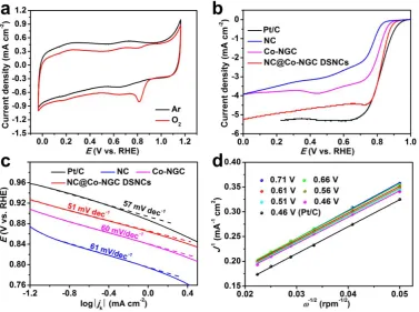
The electrocatalytic activity of NC@Co-NGC DSNCs towards ORR was first identified by
cyclic voltammograms (CV) tests conducted in Ar or O2- saturated 0.1 M KOH electrolyte at a
scan rate of 10 mV s−1 (Figure 4a). A substantial reduction process is found to occur at ca. 0.81
V versus reversible hydrogen electrode (RHE) in O2-saturated 0.1 M KOH solution, whereas
featureless quasi-rectangular voltammogram is observed within the same voltage window in
Ar-saturated electrolyte. To gain deeper insight into electrocatalytic activity and kinetics of
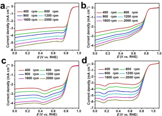
NC@Co-NGC DSNCs towards ORR, linear sweep voltammograms (LSVs) are recorded on a
rotating disk electrode (RDE) a rotation rate of 1600 rpm in O2-saturated 0.1 M KOH electrolyte
at a scan rate of 10 mV s-1 (Figure 4b). The curves of NC@Co-NGC DSNC electrodes show
obvious plateau with an onset potential of ca. 0.92 V and a half-wave potential (E1/2) of 0.82 V,
which is comparable to those of Pt/C (0.96 V, E1/2 = 0.82 V), and outperform most previously
reported carbon-based ORR catalysts (Table S1). Moreover, the unique and wide current plateau
from 0.7 to 0 V observed in the case of the NC@Co-NGC DSNC electrode represents a
diffusion-controlled process corresponding to the efficient four-electron-dominated ORR
pathway.[38] To demonstrate the advantage of NC@Co-NGC DSNCs in oxygen electrocatalysis,
the ORR performance of solid NC, Co-NGC and Co-NGC@NC particles is also investigated
under identical conditions (Figure S13 and FigureS14a). In comparison with NC@Co-NGC
DSNCs, they exhibit higher onset overpotential (0.33 V for Co-NGC, 0.36 V for NC, 0.34 V
for NGC@NC) and half-wave potential (0.8 V for NGC, 0.73 V for NC, 0.79 V for
Co-NGC@NC), as can be seen in Figure 4b and Figure S14a. The superior catalytic activity of
NC@Co-NGC DSNCs towards ORR is further verified by the Tafel plots obtained from the
polarization curves. The NC@Co-NGC DSNC has a Tafel slope of 51 mV dec−1, much lower
than that of NC (61 mV dec−1), Co-NGC (60 mV dec−1) and even Pt/C (57 mV dec−1),
suggesting the favourable ORR kinetics in the NC@Co-NGC DSNCs electrocatalyst with a
unique hollow nanostructure (Figure 4c). The apparent electrochemical surface area (ECSA)
10
(Cdl), which is typically used to represent the ECSA (Figure S15).[39-41] The NC@Co-NGC
possesses over 60 % higher Cdl than that of Co-NGC, revealing the positive effect of hollow
nanostructure on electrocatalytic activity.
The electron transfer number per oxygen molecule (n) and kinetic limiting current density (Jk)
for ORR is determined from the LSV curves (Figure S16) according to the Koutechy-Levich
(K-L) equation. The K-L plots of NC@Co-NGC DSNCs manifest good parallel linearity over
the potential ranging from 0.71 to 0.46 V, suggesting first-order reaction kinetics for ORR
(Figure4d).[42] It is noted that the NC@Co-NGC DSNCs exhibit a similar slope with that of
Pt/C electrodes. The n is determined to be ∼4.0, indicating that the ORR proceeds via a
four-electron-transfer scheme involving the in situ OH- formation in alkaline medium, which are
further confirmed by the rotating ring-disk electrode (RRDE) measurements (FigureS16).
[43-45] The NC@Co-NGC DSNC catalyst still shows an equal Jk of 12.8 mA cm−2 to that of Pt/C,
which is much higher than that of NC (3.2 mA cm−2) and Co-NGC (7.9 mA cm−2) catalyst.
(Figure S17). In comparison with Pt/C catalyst, the NC@Co-NGC DSNC catalyst exhibits
superior durability and higher resistance to the methanol cross-over effect in oxygen-saturated
0.1 M KOH (FigureS18). Furthermore, the NC@Co-NGC DSNC catalyst also shows excellent
ORR activity in acidic medium. They exhibit much lower onset overpotential (0.5 V) than that
of Co-NGC (0.57 V) and NC (0.63 V) electrodes, as well as superior stability to commercial
Pt/C catalysts (FigureS19).
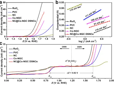
The oxygen evolution activities of NC@Co-NGC DSNC catalysts are also evaluated in O2
-saturated 0.1 M KOH solution with iR-correction. The NC@Co-NGC DSNC catalyst reaches
a current density of 10 mA cm−2 (a value expected for a 10% efficient solar water-splitting
device) at a potential (Ej=10) of 1.64 V, which is compares favorably to that of RuO2 (1.60 V), but much lower than those of Co-NGC (1.70 V), Co-NGC@NC (1.68 V), Pt/C (1.82 V) and
other reported catalysts (Figure 5a, Figure S14b and Table S1). Also, NC@Co-NGC DSNC
11
Co-NGC (100 mV dec−1), RuO
2 (110 mV dec−1) and Pt/C (171 mV dec−1) (Figure 5b),
suggesting the favorable OER kinetics in hollow nanostructured electrocatalyst. Much
enhanced electrocatalytic activities are also observed for NC@Co-NGC DSNC electrodes in 1
M KOH electrolyte, where the onset potential is close to that of RuO2 catalyst (FigureS20a).
The stability test results demonstrate that the NC@Co-NGC DSNC catalyst is very stable for
the OER, whereas RuO2 exhibits a rapid voltage increase at the constant current of 10 mA cm
-2 in short time in 0.1 M KOH (FigureS20b).
The pyrolysis temperature is a critical factor in terms of tuning the activity of NC@Co-NGC
DSNC electrocatalysts due to its significant effect on the chemical composition and structure
of the ZIF-derived products. As discussed above, the NC@Co-NGC DSNC made at 800 °C due
to the formation of Co-NGC shells exhibits the highest current density and the lowest
overpotential for ORR and OER (FigureS21). Lower annealing temperature (e.g., 600-700 oC),
however, yields the poor conductive composites made of carbon and Co nanoparticles of several
nanometers as a result of inadequate graphitization process and carbonthermal reduction of
metal oxides, accompanied with lower specific surface area (359 m2 g-1) (Figure S8, Figure
S22a-c and Figure S23). While annealing at higher temperature (e.g., 900 oC) is not favorable
for retaining high N-doping level in whole architecture and high specific surface area as a result
of the destruction of micropores (FigureS22d, e and FigureS23). In this case, the Co particles
with much larger size of tens to a hundred nanometer are yielded due to strong mobility and
severe fusion of metal particles, which are less stable and can be easily removed by acidic
etching (FigureS22f). Meanwhile, the N content is also reduced to 4 at.% by increasing the
annealing temperature from 800 to 900 oC, and the atomic ratio of pyridinic N in total N is
decreased from 70 to 45 % (Figure S24d). The loss of N and stable Co in the hybrids
significantly reduces the charge transfer and delocalization on carbon lattice and more
importantly, weakens the interaction and electron transfer between carbon and metal atoms (to
12
reactive intermediates on large ECSA that help to accelerate the ORR and OER.[12, 45]. In the
sample annealed at 800 oC, the ratio of Co-NGC in NC@Co-NGC DSNCs also affects their
electrocatalytic performance. The NC@Co-NGC DSNCs with 16.8 wt.% Co shows the lowest
overpotential to the benchmark nanocage catalysts with lower (e.g., 9.6 wt.%) or higher (e.g.,
28.2 wt.%) Co content towards ORR/OER because of more electrochemical active phase than
the former but higher specific surface area than that of the latter (FigureS25-27).
The application potential of the NC@Co-NGC DSNC materials as bifunctional oxygen
electrocatalysts has been explored, and the overall oxygen electrode activity is evaluated by the
difference of OER and ORR metrics (ΔE = Ej=10 − E1/2). Remarkably, the NC@Co-NGC DSNCs exhibit a ΔE of 0.82 V, much lower than that of Pt/C (0.94 V), RuO2 (1.0 V) and
Co-NGC (0.95 V), as well as most of the bifunctional catalysts reported to date such as metal-free
carbon hybrids (e.g., N, S-carbon nanosheet, ΔE = 0.88 V) and transition metal oxides (e.g.,
MnCo2O4/N-CNT, ΔE = 1.02 V) (Figure 5c and Table S1).[38],[46] Motivated by the superior
catalytic activity of the NC@Co-NGC DSNCs for both ORR and OER, the proof-to-concept
tests were conducted to demonstrate the feasibility of NC@Co-NGC DSNCs as the air cathode
catalyst in primary Zn-air batteries (FigureS28a). The open-circuit voltage of the Zn-air battery
with NC@Co-NGC DSNC electrode is 1.45 V, which is comparable to the batteries with Pt/C
electrode (1.46 V) but higher than that of RuO2 electrode (1.31 V) (FigureS28b). Three
coin-type Zn-air batteries with NC@Co-NGC DSNC catalysts can be connected in series to light a
light-emitting diode (LED) array panel (11×44, 3.7 V) (Figure S28c). The batteries with
NC@Co-NGC DSNCs as cathode catalyst exhibit high capacities of ca. 617, 602, 565, and 537
mA h gZn−1 at the current densities of 2, 5, 10 and 20 mA cm−2, respectively (FigureS28d).
These values are higher than that of the primary batteries with Pt/C catalyst, which deliver lower
capacities of ca. 580, 535, 510 and 495 mA h gZn−1 at identical current densities (Figure S28e).
The peak power density of the Zn-air battery with NC@Co-NGC DSNC electrode is 109 mW
13
batteries is evaluated using identical cell configuration except add Zn(Ac)2 (0.2 M) into 6 M
KOH electrolyte (Figure S30a). The charging and discharging polarization curves of
rechargeable Zn-air batteries with NC@Co-NGC DSNC, Pt/C or RuO2 as cathode catalysts are
shown in Figure S30b. The NC@Co-NGC DSNC catalyst exhibits comparable discharging
performance to Pt/C catalyst at both low (e.g., 20 mA cm-2) and high current densities (e.g., 80
mA cm-2), but significantly outperforms RuO
2 catalysts in rechargeable Zn-air batteries. Upon
charging, the NC@Co-NGC DSNC catalyst shows substantially lower overpotential for driving
OER than that of Pt/C and RuO2 catalysts at the current densities of up to 40 mA cm-2, showing
reliable bifunctionally electrocatalytic properties. The rechargeable Zn-air batteries with
NC@Co-NGC DSNC catalyst exhibit superior lifetime (56 h) and discharging voltage retention
(77.5%) to that with Pt/C (14 h, 50 %) or RuO2 (33 h, 59 %) catalyst upon discharging-charging
at a current density of 10 mA cm−2, showing good reversibility and durability (FigureS30c-e).
This performance may be further enhanced by further optimizing the cell configuration, e.g.,
the three-electrode cells that OER and ORR electrocatalysts are loaded onto two separate
electrodes for charge and discharge,[45, 47] which can prevent the bifunctional catalyst from
coming into contact with the oxidative (or reductive) potential during ORR (or OER).
Apparently, the Co-NGC shells in NC@Co-NGC DSNCs contribute largely to the catalytic
activities for both ORR and OER while the hollow nanostructure accelerates the reaction
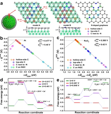
kinetics. To gain atomistic insight into the origin of bifunctional electrochemical activity,
first-principles calculation in terms of density function theory (DFT) methods is performed to
determine the active sites and catalytic reactions over Co-NGC shells. As the radius of realistic
Co-embedded N-doped graphitic carbon structures in Co-NGC shells attains several
nanometers, a slab model instead of cluster model is used to represent the Co-NGC surface
where ORR and OER are predominant. It consists of N-doped graphene monolayer adsorbed
on (111) surface of the face-centered cubic(fcc) Co crystal (Figure 6a). The (111) plane of fcc
14
cell parameters are very close with lattice mismatch below 1%. Consequently, Co-NGC
comprises of two types of C sites: on right top or hollow sites with respect to the Co lattice
(denoted as the top-site C and hollow-site C, respectively), and the former is coordinated with
underlying Co atoms. According to the experimental results, pyridinic and graphitic-type N
atoms are uniformly substituted into graphene at a doping level of ca. 6 at.%. Two models of
Co-NGC structure are thus considered in terms of the location of N dopants: on the right top or
hollow sites with respect to the Co lattice (denoted as model A and B, respectively). Mulliken
charge analysis indicates little difference between the two models, which both present electron
transfer of 0.26 e from each Co atom to the graphitic layer, giving 0.15 and 0.1 e to the top-site
C and hollow-site C atoms, respectively. The N dopants in the graphitic sheets further induce
charge redistribution to the C atoms nearby, which directly affect their electrocatalytic
performance to be discussed below.
The key to high activity of a bifunctional ORR/OER electrocatalyst is the favorable strength
of the interaction with the reaction intermediates involved in both reactions. The weak
adsorption of the intermediates on active sites results in low efficiency of the reaction, while
too strong binding between them starves one of or even all the reactions by blocking the
catalytic surface. To work out the ORR and OER activities of the Co-NGC catalysts, the
adsorption free energy of the oxygenated intermediate species, including the OOH*, OH* and
O*, involved in ORR and OER at different C sites in two Co-NGC models is calculated. The
overpotentials of ORR (ηORR) and OER (ηOER) are then determined by the standard hydrogen
electrode (SHE) method.[48] For comparison, the model of an isolated N-doped graphitic carbon
sheet (NGC) with the same scale is also constructed to calculate the ORR/OER overpotentials
(Figure 6a). In alkaline solution, ORR and OER occur via the four electron reaction paths,
listed as equations (S5) to (S12) in Supporting Information. The ηORR versus the adsorption free
energy of OOH* (ΔGOOH*) for various reactive sites on Co-NGC surface of both models
15
adsorption of OOH* on carbon surface of Co-NGC structure is greatly enhanced, as indicated
by the much lower adsorption free energy (ΔGOOH*) at different C sites (3.9 - 4.9 eV) than that
of the NGC without Co involved (4.9 - 5.8 eV). Specifically, the hollow-site C atoms with
strong bonding with OOH* exhibit much lower ηORR of 0.477 - 0.68 V than that of the top-site
C atoms (ηORR = 0.87 - 1.23 V) coordinated to underlying Co. For the C sites in close proximity
to doped N atoms, the bonding with oxygenated species is too strong (Mulliken charge of +0.06
e) to suppress the further reaction, thus leading to high ηORR of 0.81 - 0.98 V. Among the
hollow-site C atoms, those para to graphitic N in model A (Mulliken charge of −0.-09 e) exhibit the
lowest ηORR of 0.477 V, approaching the value of Pt identified theoretically (0.45 V).[49] In
contrast, the NGC model shows very high ηORR of above 1.24 V due to the weak bonding of
OOH* species over the carbon surface. For the OER process, the hollow-site C atoms exhibit
the strongest adsorption of OOH* relative to O* species and high catalytic activity with ηOER
of 0.388 - 0.74 V, which is superior to that of top-site C atoms (ηOER = 0.82 - 1.48 V) and the C
atoms in close proximity to doped N atoms (ηOER = 1.56 - 1.65 V) on Co-NGC surface (Figure
6c). A lowest ηOER of 0.388 V can be achieved at the hollow-site C atoms para to pyridinic N in
model A (Mulliken charge of −0.1 e), which is even lower than the theoretical value RuO2 (0.42
V)[50]. In the case of NGC, the C atoms in close proximity to doped N atoms have the lowest
ηOER of 0.5 V and ηORR of 1.2 V, and the rest shows high overpotentials of over 1.1 - 1.67 V for
both reactions.[51, 52] The highly active hollow-site C atoms towards ORR/OER (ηORR/OER < 0.65
V) account for 47% of the total C atoms in the Co-NGC structure, which endows the catalyst
with high efficiency towards oxygen electrocatalysis.
The elementary reactions of ORR and OER over the identified active sites of Co-NGC
structure are further investigated at various electrode potential (U). At U = 0, the overall reaction
for the four electron transfer steps is exothermic by 1.844 eV in alkaline media with pH = 13
for ORR (Figure 6d). The equilibrium potential is 1.844/4 = 0.461 V, at which the overall
16
has to be overcome for the formation of OOH*. By applying a negative voltage U = −0.017 V
to the electrodes, all the reaction steps become downhill and can occur spontaneously, which
corresponds to a ORR overpotential of 0.478 V. For the OER, the opposite process of ORR
applies. At equilibrium potential U = 0.461 V, the formation of OOH* from O* and OH− species
are associated with the highest energy barrier of 0.387 eV (Figure 6e). This energy barrier
disappears at U = 0.848 V, determining an OER overpotential of 0.387 V. Apparently, this leads
one to conclude that the formation of OOH* could be identified as the rate-limiting step for
ORR and OER over Co-NGC structure in alkaline media. The strong but favorable adsorption
of the OOH* intermediates on uncoordinated hollow-site C atoms in Co-NGC structure is an
essential rate-determining step to achieve high bifunctional electrocatalytic activity for both the
ORR and OER reactions.
In summary, we have developed a facile approach to prepare hybrid carbon nanocages with
N-doped carbon (NC) as inner shells and Co-N-doped graphitic carbon (Co-NGC) as outer
shells by the controlled pyrolysis of core-shelled ZIF-8@ZIF-67 crystals. The unusual
formation of hollow nanostructures is attributed to surface-stabilized contraction of
core-shelled ZIF crystals at high temperature. The integration of Co-NGC shells into robust hollow
NC structure renders the double-shelled NC@Co-NGC nanocages with high activity and
enhanced diffusion kinetics for electrochemical oxygen reduction and evolution. As the
electrocatalyst, NC@Co-NGC nanocages exhibit superior electrocatalytic activity and
durability in comparison to Pt and RuO2 catalysts towards ORR and OER, respectively, and
hold potential as the bifunctional air electrode catalysts in rechargeable Zn-air batteries with a
high peak power density of 109 mW cm-2, high capacities at the current density of 2-20 mA
cm−2 and long lifetime. The first-principles calculation reveals that the strong yet favorable
adsorption of the rate-determining intermediate (OOH*) on high density of uncoordinated
hollow-site C atoms with respect to Co lattice may account for the bifunctional electrocatalytic
17
active C sites at the para-position of doped graphitic-type and pyridinic-type N atoms exhibit
the highest activity towards ORR and OER, respectively. The present work may shed a new
insight into the design and fabrication of highly active M-N-C electrocatalysts with tuned
chemical nature, morphology and electrocatalytic bifunctions for both ORR and OER.
Supporting Information
Supporting Information is available from the Wiley Online Library or from the author. Acknowledgements
This study is partly supported by the National Natural Science Foundation of China (Nos. 51522203, 21336001 and 21361162004). ZW acknowledges the support from the Recruitment Program of Global Youth Experts, Fok Ying Tung Education Foundation (No. 151047) and Xinghai Scholarship of Dalian University of Technology. WZ thanks EPSRC for financial support to the electron microscopy facility (EP/F019580/1).
Received: ((will be filled in by the editorial staff)) Revised: ((will be filled in by the editorial staff)) Published online: ((will be filled in by the editorial staff))
[1] P. G. Bruce, S. A. Freunberger, L. J. Hardwick, J.-M. Tarascon, Nat. Mater. 2012, 11, 19. [2] M. K. Debe, Nature 2012, 486, 43.
[3] J. Suntivich, K. J. May, H. A. Gasteiger, J. B. Goodenough, Y. Shao-Horn, Science 2011,
334, 1383.
[4] G. Wu, P. Zelenay, Acc. Chem. Res. 2013, 46, 1878.
[5] J.-I. Jung, H. Y. Jeong, J.-S. Lee, M. G. Kim, J. Cho, Angew. Chem. Int. Ed. 2014, 53, 4582.
[6] T. Maiyalagan, K. A. Jarvis, S. Therese, P. J. Ferreira, A. Manthiram, Nat. Commun. 2014,
5, 3949.
[7] J. Masa, W. Xia, M. Muhler, W. Schuhmann, Angew. Chem. Int. Ed. 2015, 54, 10102. [8] M. Zeng, Y. Liu, F. Zhao, K. Nie, N. Han, X. Wang, W. Huang, X. Song, J. Zhong, Y. Li,
Adv. Funct. Mater. 2016, 26, 4397.
[9] G. Wu, K. L. More, C. M. Johnston, P. Zelenay, Science 2011, 332, 443.
[10] N. L. Torad, R. R. Salunkhe, Y. Li, H. Hamoudi, M. Imura, Y. Sakka, C.-C. Hu, Y. Yamauchi, Chem. Eur. J. 2014, 20, 7895.
[11] Y. Liu, H. Jiang, Y. Zhu, X. Yang, C. Li, J. Mater. Chem. A 2016, 4, 1694.
[12] D. Guo, R. Shibuya, C. Akiba, S. Saji, T. Kondo, J. Nakamura, Science 2016, 351, 361. [13] D. Deng, L. Yu, X. Chen, G. Wang, L. Jin, X. Pan, J. Deng, G. Sun, X. Bao, Angew. Chem.
Int. Ed. 2013, 52, 371.
[14] W.-J. Jiang, L. Gu, L. Li, Y. Zhang, X. Zhang, L.-J. Zhang, J.-Q. Wang, J.-S. Hu, Z. Wei, L.-J. Wan, J. Am. Chem. Soc. 2016, 138, 3570.
[15] K. S. Park, Z. Ni, A. P. Cote, J. Y. Choi, R. Huang, F. J. Uribe-Romo, H. K. Chae, M. O'Keeffe, O. M. Yaghi, Proc. Natl. Acad. Sci. U. S. A. 2006, 103, 10186.
[16] B. Y. Xia, Y. Yan, N. Li, H. B. Wu, X. W. Lou, X. Wang, Nat. Energy 2016, 1, 15006. [17] W. Xia, A. Mahmood, R. Zou, Q. Xu, Energy Environ. Sci. 2015, 8, 1837.
18
[19] Y. Zhao, Z. Song, X. Li, Q. Sun, N. Cheng, S. Lawes, X. Sun, Energy Storage Mater.2016,
2, 35.
[20] R. Wu, X. Qian, X. Rui, H. Liu, B. Yadian, K. Zhou, J. Wei, Q. Yan, X.-Q. Feng, Y. Long, L. Wang, Y. Huang, Small 2014, 10, 1932.
[21] L. Hou, L. Lian, L. Zhang, G. Pang, C. Yuan, X. Zhang, Adv. Funct. Mater. 2015, 25, 238. [22] F. Wu, J. T. Lee, F. Fan, N. Nitta, H. Kim, T. Zhu, G. Yushin, Adv. Mater. 2015, 27, 5579. [23] X.-Y. Yu, L. Yu, H. B. Wu, X. W. Lou, Angew. Chem. Int. Ed. 2015, 54, 5331.
[24] Z. Song, N. Cheng, A. Lushington, X. Sun, Catalysts 2016, 6, 116.
[25] J. Liu, S. Z. Qiao, J. S. Chen, X. W. Lou, X. R. Xing, G. Q. Lu, Chem. Commun. 2011, 47, 12578.
[26] P. M. Arnal, M. Comotti, F. Schuth, Angew. Chem. Int. Ed. 2006, 45, 8224.
[27] J. S. Qiu, Z. Y. Wang, S. H. Liu, Chinese Patent, State Intellectual Property Office of the P.R. China 28.07.2015, application No. 201510448674.2.
[28] J. Tang, R. R. Salunkhe, J. Liu, N. L. Torad, M. Imura, S. Furukawa, Y. Yamauchi, J. Am. Chem. Soc. 2015, 137, 1572.
[29] Y.-Z. Chen, C. Wang, Z.-Y. Wu, Y. Xiong, Q. Xu, S.-H. Yu, H.-L. Jiang, Adv. Mater.
2015, 27, 5010.
[30] R. Wu, X. Qian, K. Zhou, J. Wei, J. Lou, P. M. Ajayan, ACS Nano 2014, 22, 6297. [31] H. B. Wu, S. Wei, L. Zhang, R. Xu, H. H. Hng, X. W. Lou, Chem. Eur. J. 2013, 19, 10804. [32] R. Wu, D. P. Wang, X. Rui, B. Liu, K. Zhou, A. W. K. Law, Q. Yan, J. Wei, Z. Chen, Adv.
Mater. 2015, 27, 3038.
[33] W.-B. Luo, X.-W. Gao, S.-L. Chou, J.-Z. Wang, H.-K. Liu, Adv. Mater. 2015, 27, 6862. [34] Q. Lin, X. Bu, A. Kong, C. Mao, F. Bu, P. Feng, Adv. Mater. 2015, 27, 3431.
[35] Z. Wang, Y. Dong, H. Li, Z. Zhao, H. Bin Wu, C. Hao, S. Liu, J. Qiu, X. W. Lou, Nat. Commun. 2014, 5, 5002.
[36] F. Zheng, Y. Yang, Q. Chen, Nat. Commun. 2014, 5, 5261.
[37] J. G. Guan, F. Z. Mou, Z. G. Sun, W. D. Shi, Chem. Commun. 2010, 46, 6605. [38] K. Qu, Y. Zheng, S. Dai, S. Z. Qiao, Nano Energy 2016, 19, 373.
[39] C. C. L. McCrory, S. Jung, J. C. Peters, T. F. Jaramillo, J. Am. Chem. Soc. 2013, 135, 16977.
[40] Z.-Q. Liu, H. Cheng, N. Li, T. Y. Ma, Y.-Z. Su, Adv. Mater. 2016, 28, 3777. [41] H. B. Wu, B. Y. Xia, L. Yu, X.-Y. Yu, X. W. Lou, Nat. Commun. 2015, 6, 6512.
[42] Y. Hou, T. Huang, Z. Wen, S. Mao, S. Cui, J. Chen, Adv. Energy Mater. 2014, 4, 1400337. [43] S. Guo, S. Zhang, L. Wu, S. Sun, Angew. Chem. Int. Ed. 2012, 51, 11770.
[44] Y. Liang, Y. Li, H. Wang, J. Zhou, J. Wang, T. Regier, H. Dai, Nat. Mater. 2011, 10, 780. [45] J. Zhang, Z. Zhao, Z. Xia, L. Dai, Nat. Nanotechnol. 2015, 10, 444.
[46] A. Zhao, J. Masa, W. Xia, A. Maljusch, M.-G. Willinger, G. Clavel, K. Xie, R. Schlögl, W. Schuhmann, M. Muhler, J. Am. Chem. Soc. 2014, 136, 7551.
[47] Y. Li, M. Gong, Y. Liang, J. Feng, J. E. Kim, H. Wang, G. Hong, B. Zhang, H. Dai, Nat. Commun. 2013, 4, 1805.
[48] J. Rossmeisl, Z. W. Qu, H. Zhu, G. J. Kroes, J. K. Nørskov, J. Electroanal. Chem. 2007,
607, 83.
[49] J. K. Nørskov, J. Rossmeisl, A. Logadottir, L. Lindqvist, J. R. Kitchin, T. Bligaard, H. Jónsson, J. Phys. Chem. B 2004, 108, 17886.
[50] I. C. Man, H.-Y. Su, F. Calle-Vallejo, H. A. Hansen, J. I. Martínez, N. G. Inoglu, J. Kitchin, T. F. Jaramillo, J. K. Nørskov, J. Rossmeisl, ChemCatChem 2011, 3, 1159.
[51] H. B. Yang, J. Miao, S. F. Hung, J. Chen, H. B. Tao, X. Wang, L. Zhang, R. Chen, J. Gao, H. M. Chen, L. Dai, B. Liu, Sci. Adv. 2016, 2, e1501122.
19 Figures and captions
20
21
[image:21.595.82.513.70.287.2]22
[image:22.595.108.486.104.385.2]23
[image:23.595.115.482.105.378.2]24
[image:24.595.102.492.67.469.2]25 The table of contents
A new strategy is developed for constructing hollow nanostructured bifunctional ORR/OER electrocatalyst with integrated high activity and fast kinetics by surface-stabilized heterogeneous contraction of core-shelled metal-organic frameworks. The resultant double-shelled hybrid nanocages with outer shell of mesoporous Co-N-doped graphitic carbon and inner shell of microporous N-doped carbon exhibit superior electrocatalytic performance to noble metals for oxygen reduction and evolution reactions.
Keyword: oxygen electrocatalysis, bifunctional electrocatalyst, metal-organic frameworks, hollow nanostructure, first-principles calculation
Shaohong Liu, Zhiyu Wang, Si Zhou, Fengjiao Yu, Mengzhou Yu, Chang-Yang Chiang, Wuzong Zhou, Jijun Zhao* and Jieshan Qiua,*
26
Copyright WILEY-VCH Verlag GmbH & Co. KGaA, 69469 Weinheim, Germany, 2016.
Supporting Information
Metal-organic framework-derived hybrid carbon nanocages as bifunctional electrocatalyst for oxygen reduction and evolution
Shaohong Liu,a, † Zhiyu Wang,a, † Si Zhou,b, † Fengjiao Yu,c Mengzhou Yu,a Chang-Yang
Chiang,c Wuzong Zhou,c Jijun Zhaob,* and Jieshan Qiua,*
Dr. S. H. Liu, Prof. Z. Y. Wang, Dr. S. Zhou, F. J. Yu, M. Z. Yu, C. Chiang, Prof. W. Z. Zhou, Prof. J. J. Zhao, Prof. J. S. Qiu
a State Key Lab of Fine Chemicals, Carbon Research Laboratory, Liaoning Key Lab for Energy Materials and Chemical Engineering, School of Chemical Engineering, Dalian University of Technology, Dalian 116024, China.
b Education Ministry Key Lab of Materials Modification by Laser, Ion and Electron Beams, Dalian University of Technology, Dalian 116024, China
c School of Chemistry, University of St Andrews, St Andrews, KY16 9ST, United Kingdom
†These authors contribute equally to this work.
E-mail: [email protected], [email protected]
Experimental section
Synthesis of ZIF-8 and ZIF-67 particles. For the synthesis of ZIF-8, two solutions were first prepared by dissolving 3 mmol of Zn(NO3)2·6H2O in 30 mL of methanol and 12 mmol of 2-methylimidazole (2-MeIm) in 10 mL of methanol, respectively. Then, the solution of 2-MeIm was quickly poured into the solution of Zn(NO3)2·6H2O, leading to a mixed solution that was aged for 24 h at room temperature. The ZIF-8 crystals with an average edge size of around 800, 500, 300 and 150 nm could be yielded by using 5, 10, 20 and 30 mL of methanol for dissolving 2-MeIm. The as-obtained precipitates were collected by centrifugation and dried at 60 °C. ZIF-67 was synthesized with the same procedure of ZIF-8 except for the use of Co(NO3)2·6H2O as metal precursor.
Synthesis of ZIF-8@ZIF-67 core-shell structures. In a typical run, 100 mg of ZIF-8 polyhedrons with various sizes were dispersed in 30 mL of methanol. Then 150 mg of Co(NO3)2·6H2O and a methanol solution of 2-MeIm (10 mL, 32.8 mg mL−1) were added into the suspension of ZIF-8 polyhedrons under stirring. After stirring for 24 h, the ZIF-8@ZIF-67 core-shell particles were harvested by several centrifugation-rinsing cycles with methanol, followed by drying at 60 oC. For comparison, core-shelled ZIF-67@ZIF-8 particles could be
also yielded by similar approach except using ZIF-67 as the seeds and Zn(NO3)2·6H2O for the growth of ZIF-8 shell with different thickness.
Synthesis of NC@Co-NGC DSNCs. The as-prepared ZIF-8@ZIF-67 particles were annealed at 800 oC for 5 h at a ramp rate of 2 oC min−1 in flowing N
27
Material characterization. Field-emission SEM (FESEM) analysis was conducted on a JEOL JSM-6700F microscopy operated at 5 kV. Transmission electron microscopy (TEM) observation was conducted on a JEOL JEM-2011 microscopy operated at 200 kV, equipped with an Oxford Link ISIS system for elemental mapping. Powder X-ray diffraction (XRD) was performed on a PANalytical Empyrean diffractometer with Cu-Kα radiation. The surface characteristics of the samples were investigated using a Thermo ESCALAB 250 X-ray photoelectron spectrometer (XPS). The textural properties of the samples were measured by Micrometrics ASAP 2020 Surface Area and Porosity Analyzer at 77 K. TGA was carried out by a NETZSCH scientific instrument in N2, heating from room temperature to 800 °C at a ramp rate of 10 °C min−1.
Electrochemical measurement. All electrocatalytic measurements were performed using a CHI 760D electrochemical workstation with a three-electrode system at room temperature. A 0.1 M KOH aqueous solution saturated with O2 was used as the electrolyte unless otherwise stated. A glassy-carbon rotating disk electrode (RDE) or a rotating ring-disk electrode (PINE) was used as working electrode while a Pt foil and an Ag/AgCl electrode saturated with KCl solution was employed as counter and reference electrode, respectively. All potentials measured against an Ag/AgCl electrode in this study, was converted to potential versus RHE according to Evs RHE = Evs Ag/AgCl + 0.059 pH + 0.197. To prepare the working electrode, 4 mg of the sample was ultrasonically dispersed in a mixture of ethanol (0.5 mL), deionized water (0.485 mL) and Nafion (0.015 mL, 5 wt.%) to form a uniform suspension. A part of the catalyst ink was then loaded onto a glassy-carbon electrode by microsyringe with a mass loading of 0.4 mg cm−2 for all samples including commercial Pt/C (20 wt%, Johnson Matthey) and RuO2 (Sigma-Aldrich). The polarization curves for ORR were recorded at different rotating rate from 400 to 2000 rpm with a scan rate of 10 mV s-1. Methanol tolerance of the catalysts was tested by conducting the ORR in the presence of methanol (14 mL, 3 M) in O2-saturated KOH solution (100 mL, 0.1 M) by the similar procedure. For the OER test, the polarization curves were obtained at a rotating rate of 1600 rpm with a scan rate of 10 mV s−1, corrected by iR-compensation. The electrical double layer capacitance (Cdl) of the samples was measured from double-layer charging curves using cyclic voltammograms (CVs) in a small potential range of 1.10-1.15 V in 0.1 M KOH at the scan rate of 5, 10, 20, 30 and 40 mV s-1. The plot of the current density (at 1.14 V) against the scan rate has a linear relationship and its slope is the Cdl of the tested catalyst.
The overall electron transfer numbers per oxygen molecule involved in a typical ORR process can be calculated from the slopes of Koutecky-Levich (K-L) plots using the following equation:
1/j = 1/jk + 1/Bω1/2 (S1) where jk is the kinetic current at a constant potential and ω represents the electrode rotating speed. B can be determined from the slope of the K-L plots based on Levich equation:
B = 0.2nF(Do2)2/3υ 1/6Co2 (S2) where n represents the transferred electron number per oxygen molecule, F is Faraday constant (96485 C mol 1), Do
2 is the diffusion coefficient of O2 (1.9×10 5 cm2 s 1), υ is the kinetic viscosity (υ = 0.01 cm2 s 1) and Co2 is the bulk concentration of O2 (1.2×10 6 mol cm 3). When expressing the rotation speed in rpm, the constant 0.2 is applied.
In Tafel plot, the kinetic current was calculated from the mass-transport correction of RDE data by the followed equation:
28
where j is the current density and jL is the limiting current density.
RRDE technique was also employed to determine the reaction pathway (electron transfer number) for ORR by detecting the HO2- formation, in which the ring potential was held constantly at 1.50 V vs. RHE. The disk electrode was scanned at a rate of 10 mV s−1 with a rotation rate of 1600 rpm. The electron transfer number (n) was determined by the followed equation:
n = 4Id/(Id + Ir/N) (S4) where Id is disk current, Ir is ring current, and N is the current collection efficiency.
Zn-air battery test. The primary Zn-air batteries were tested in CR2032 coin-type cells with a polished Zn plate as the anode, a cellulose film as the separator and 6 M KOH solution as the electrolyte. The air cathodes were prepared by casting a mixture of catalyst (NC@Co-NGC DSNC, Pt/C or RuO2), Nafion (5 wt.%) and ethanol onto a gas diffusion layer (TGP-H-060, Torray), followed by vacuum drying at 80 oC for 12 h. The rechargeable Zn-air batteries were tested using identical cell configuration except add Zn(Ac)2 (0.2 M) into 6 M KOH electrolyte. The average catalyst loading was 0.5 mg cm−2. Battery tests were performed on a LAND CT2001A tester in air. Galvanostatic discharge and charge cycling was conducted by a recurrent galvanic pulse method at a constant current density of 10 mA cm−2 with each cycle for 10 min. Polarization curves were collected at a scan rate of 10 mV s−1.
Computational method. Density functional theory (DFT) calculations are performed by Vienna ab initio simulation package (VASP)1 using the plane wave basis set with an energy cut-off of 500 eV, the projector augmented wave (PAW) potentials2, and the generalized gradient
approximation (GGA) parameterized by Perdew, Burke and Ernzerhof (PBE) for the exchange-correlation functional3. As the radius of realistic Co-embedded N-doped graphitic carbon structures in Co-NGC shells attains several nanometers, a slab model consisting of single layer N-doped graphene adsorbed on (111) surface of fcc Co is used to represent the Co-NGC surface. A three-layer slab model is adopted for the Co crystal, with a vacuum region of 14 Å in the out-of-plane direction. The in-plane lattice parameters of graphene (2.46 Å) and Co (2.51 Å) are very close4, 5, and thus we expand and compress their in-plane lattice by 1%, and use a lattice parameter of 2.48 Å for both materials. Consequently, Co-NGC comprise of two types of C sites: on right top or hollow sites with respect to the Co lattice (denoted as the top-site C and hollow-site C, respectively). To accommodate the N dopants in graphene, a periodic supercell with the in-plane dimension consisting of 6×6 unit cells is used for both graphene and Co. The Brillouin zones of the supercell are sampled by 2×2×1 uniform k-point meshes. The model structures are optimized by only ionic and electronic degrees of freedom using thresholds for the total energy of 10−4 eV and force of 0.02 eV/Å. During the structural relaxation, the bottom layer of Co atoms is fixed to mimic a semi-infinite metal solid. The semi-empirical dispersion-corrected DFT-D3 scheme proposed by Grimme6 is used to describe the van der Waals interactions between graphene and the Co surface.
29
To evaluate the ORR and OER activities, we calculate the adsorption free energy of the oxygenated intermediate species, including OOH*, OH* and O*, involved in ORR and OER on different C sites of both models. The overpotentials of ORR and OER are then determined by the standard hydrogen electrode (SHE) method developed by Norskov et al.7, 8, 9.
In alkaline medium, the ORR could occur in the following 4-electron reaction pathway10, 11: * + O2 (g) + H2O (l) + e−→ OOH* + OH− (S5)
OOH* + e−→ O* + OH− (S6)
O* + H2O (l) + e−→ OH* + OH− (S7)
OH* + e−→ * + OH− (S8)
where * represents an active site on the graphene surface.
In alkaline medium, the OER could occur via a 4-electron reaction pathway:
* + OH−→ OH* + e− (S9)
OH* + OH−→ O* + H2O (l) + e− (S10)
O* + OH−→ OOH* + e− (S11)
OOH* + OH−→ * + O2 (g) + H2O (l) + e− (S12)
The adsorption energies (ΔEads) of OOH*, OH* and O* are calculated by referring their DFT total energy to that of a clean Co-NGC surface, and H2O and H2 in the gas phase. The adsorption free energy (ΔGads) is obtained by
ΔGads = ΔEads + ΔZPE - TΔS (S13) where ΔZPE and ΔS are the contributions to the free energy from the zero-point vibration energy and entropy, respectively12. Only the vibration entropy contribution is considered here. The calculation of vibrational frequencies of the OOH*, OH* and O* on the Co-NGC surface gives ΔZPE - TΔS = 0.32, 0.30 and 0.05 eV, respectively (T = 298 K). It is in good agreement with the previous theoretical results7, 8. Entropy contributions of -0.14 eV and -0.11 eV are used for gaseous H2 at the standard condition and for gaseous H2O at the equilibrium pressure of 0.035 bars in contact with liquid water at 298 K, respectively7, 13. Supplementary Fig. 19 shows the ΔGads of the oxygenated species on different C sites in the model A and B, compared with that of an isolated NGC layer. The adsorption free energy of OOH*, OH* and O* are linearly correlated, and in good accordance with the previous studies8, 14.
For each reaction step in ORR/OER, the Gibbs free energy of formation is given by
ΔG = ΔEDFT + ΔZPE - TΔS - eU (S14) where ΔEDFT, ΔZPE and ΔS are the change of DFT total energy, zero-point energy, and entropy from the initial to the final state; U is the electrode potential and e is the charge transferred. The reference potential is set to be that of the standard hydrogen electrode7, 9. The overpotential of ORR is then determined by7
ηORR = ΔGmax/e + 0.461 V (S15) where ΔGmax is the maximum Gibbs free energy of formation among the four reaction steps; 0.461 V is the equilibrium potential at the standard condition and in an alkaline environment with pH = 138, 14. At the equilibrium potential, the overall reaction O2(g) + H2O(l) + 4e− →
4OH− has a zero Gibbs free energy of formation. For OER, the overpotential is then determined
30
31
Figure S1. (a) XRD patterns of ZIF-8, ZIF-67 and core-shelled ZIF-8@ZIF-67 polyhedrons. Inset is the digital photo of the samples. (b) FESEM image and (c) TEM image of 8@67 polyhedrons. (d) Elemental mapping showing the distribution of C, N, Zn, and Co in ZIF-8@ZIF-67 polyhedrons.
Figure S2. FESEM images of (a) ZIF-8 and (b) ZIF-67 particles.
32
Figure S4. HRTEM image of a Co nanoparticle encapsulated in several graphitic carbon layers in Co-NGC shell.
Figure S5. Raman spectra of NC@Co-NGC DSNCs, ZIF-67 derived Co-NGC and ZIF-8 derived NC.
33
Figure S7. (a) C 1s and (b) O 1s XPS spectra of NC@Co-NGC DSNCs.
Figure S8. TGA curves of ZIF-8, ZIF-67 and ZIF-8@ZIF-67 samples in flowing N2 at a ramp rate of 10 oC min−1.
[image:33.595.121.478.68.211.2] [image:33.595.134.462.505.720.2]34
[image:34.595.201.392.65.219.2]Figure S10. XRD patterns of the samples obtained by annealing core-shell ZIF-8@ZIF-67 particles at different temperatures.
Figure S11. (a) FESEM and (b) TEM images of ZIF-8 derived NC particles. (c) FESEM and (d) TEM images of ZIF-67 derived Co-NGC particles. Both of them are obtained by annealing the parent ZIF at 800 oC. (e) Schematic of the formation mechanism of ZIF-derived solid particles.
[image:34.595.139.459.277.436.2] [image:34.595.162.433.519.700.2]35
Figure S13. LSVs of (a) NC@Co-NGC DSNC, (b) NC, (c) Co-NGC and (d) Pt/C catalysts at different rotation rates in O2-saturated 0.1 M KOH solution at a scan rate of 10 mV s−1.
Figure S14. (a) ORR and (b) OER polarization curves of Co-NGC@NC and NC@Co-NGC DSNC catalysts, measured at a rotation rate of 1600 rpm in O2-saturated 0.1 M KOH solution at a scan rate of 10 mV s−1.
[image:35.595.128.469.565.697.2]36
[image:36.595.133.467.72.204.2]Figure S16. (a) RRDE measurements of NC, Co-NGC, NC@Co-NGC DSNC and Pt/C catalysts at a rotation rate of 1600 rpm in O2-saturated 0.1 M KOH solution at a scan rate of 10 mV s−1. (b) The electron transfer number for ORR on NC, Co-NGC, NC@Co-NGC DSNC and Pt/C catalysts, obtained based on the disk and ring currents in RRDE measurements (ring potential: 1.50 V).
Figure S17. Kinetic currents of various samples for ORR at 0.71 V vs. RHE.
[image:36.595.186.412.316.488.2] [image:36.595.127.465.547.666.2]37
Figure S19. (a) ORR polarization curves of NC@Co-NGC DSNCs, Pt/C, Co-NGC and NC catalyst at a rotation rate of 1600 rpm at a scan rate of 10 mV s−1. (b) LSVs of NC@Co-NGC DSNCs at different rotation rates at a scan rate of 10 mV s−1. (c) Koutecky-Levich plots of NGC DSNCs at various potentials. (d) Chronoamperometric responses of NC@Co-NGC DSNCs and Pt/C catalyst at 0.50 V. All the catalysts are tested in O2-saturated 0.5 M H2SO4 solution, except for Pt/C that is tested in 0.1 M HClO4 to avoid the catalyst poisoning caused by bisulfate.
[image:37.595.130.469.485.606.2]38
[image:38.595.130.468.74.205.2]Figure S21. (a) ORR and (b) OER polarization curves of NC@Co-NGC DSNC catalysts obtained at different annealing temperatures, measured at a rotation rate of 1600 rpm in O2-saturated 0.1 M KOH solution at a scan rate of 10 mV s−1.
Figure S22. (a) FESEM and (b, c) TEM images of NC@Co-NGC DSNCs obtained at 700 oC. (d) FESEM and (e) TEM images of NC@Co-NGC DSNCs obtained at 900 oC. (f) The large Co particles in this sample can be easily removed by acidic etching.
[image:38.595.156.440.288.478.2] [image:38.595.100.503.562.713.2]39
Figure S24. (a) XPS full scans of NC@Co-NGC DSNCs annealed at various temperatures. (b, c) N 1s XPS spectra of NC@Co-NGC DSNCs annealed at (b) 700 oC and (c) 900 oC, respectively. (d) The content variation of pyridinic-type N, pyrrolic-type N and graphitic-type N in NC@Co-NGC DSNCs annealed at different temperatures.
[image:39.595.111.484.398.538.2]40
Figure S26 (a, b) FESEM and (c) TEM images of NC@Co-NGC DSNCs with Co content of 9.6 wt.%. (d, e) FESEM and (f) TEM images of NC@Co-NGC DSNCs with Co content of 28.2 wt.%.
[image:40.595.169.428.70.244.2] [image:40.595.124.470.315.450.2]41
Figure S28. (a) Schematic of the primary Zn-air battery with a carbon paper casted with catalysts as air cathode, a Zn plate as anode and a glassy fiber membrane soaked with aqueous KOH electrolyte as the separator. (b) Open-circuit voltages of primary Zn-air batteries with NC@Co-NGC DSNC, RuO2 and Pt/C catalysts, respectively. (c) Optical image of a LED panel lighted by three Zn-air batteries in series. (d, e) Discharge curves of primary Zn-air batteries with NC@Co-NGC DSNCs and Pt/C as cathode catalyst at various current densities of 2-20 mA cm−2, respectively.
[image:41.595.130.468.69.400.2] [image:41.595.170.426.539.711.2]42
Figure S30. (a) Schematic of the rechargeable Zn-air battery. (b) Discharge-charge polarization curves of rechargeable Zn-air batteries with NC@Co-NGC DSNCs, Pt/C or RuO2 as cathode catalysts. (c-e) Galvanostatic charge-discharge cycling performance of rechargeable Zn-air batteries with Pt/C, RuO2 and NC@Co-NGC DSNC catalysts at a current density of 10 mA cm−2, respectively.
[image:42.595.114.484.556.693.2]43
Table S1. A comparison on the electrocatalytic activity of the recently reported bifunctional catalysts. Catalyst ORR onset potential (V vs. RHE) ORR half-wave potential (E1/2) (V vs. RHE)
OER over-potential @10 mV cm-2
(Ej=10) (V vs.
RHE)
Overall oxygen electrode
activity
ΔE (Ej=10
- E1/2) (V)
Catalyst loading (mg cm-2)
Electrolyt
e Reference
NC@Co-NGC
DSNCs 0.92 0.82 1.64 0.82 0.4
0.1 M KOH
This work
RuO2 0.85 0.61 1.61 1.00 0.4 0.1 M KOH work This
Pt/C 0.96 0.82 1.76 0.94 0.4 0.1 M KOH work This
N, S-carbon
nanosheet 0.92 0.77 1.65 0.88 0.2
0.1 M
KOH [S15]
P-g-C3N4 on
carbon paper 0.94 0.67 1.63 0.96 ~0.2
0.1 M
KOH [S16]
MnxOy/N
-carbon 0.85 0.81 1.68 0.87 0.21
0.1 M
KOH [S17]
CoO/N-
graphene 0.90 0.81 1.57 0.76 0.7 1 M KOH [S18]
Co3O4/N-
graphene 0.86 0.83 1.54 0.71 1.0 1 M KOH [S19]
MnCo2O4/N-
CNT 0.85 0.63 1.65 1.02 0.21
0.1 M
KOH [S20]