Fast sweep-rate plastic Faraday force magnetometer with simultaneous
sample temperature measurement
D. Slobinsky, R. A. Borzi, A. P. Mackenzie, and S. A. Grigera
Citation: Rev. Sci. Instrum. 83, 125104 (2012); doi: 10.1063/1.4769049
View online: http://dx.doi.org/10.1063/1.4769049
View Table of Contents: http://rsi.aip.org/resource/1/RSINAK/v83/i12
Published by the AIP Publishing LLC.
Additional information on Rev. Sci. Instrum.
Journal Homepage: http://rsi.aip.org
Journal Information: http://rsi.aip.org/about/about_the_journal
Top downloads: http://rsi.aip.org/features/most_downloaded
Fast sweep-rate plastic Faraday force magnetometer with simultaneous
sample temperature measurement
D. Slobinsky,1R. A. Borzi,2A. P. Mackenzie,1and S. A. Grigera1,3
1SUPA, School of Physics and Astronomy, University of St Andrews, St Andrews KY16 9SS, United Kingdom 2Instituto de Investigaciones Fisicoquímicas Teóricas y Aplicadas (UNLP-CONICET) and Departamento de
Física, UNLP, La Plata 1900, Argentina
3Instituto de Física de Líquidos y Sistemas Biológicos, UNLP-CONICET, La Plata 1900, Argentina
(Received 4 September 2012; accepted 11 November 2012; published online 7 December 2012)
We present a design for a magnetometer capable of operating at temperatures down to 50 mK and magnetic fields up to 15 T with integrated sample temperature measurement. Our design is based on the concept of a Faraday force magnetometer with a load-sensing variable capacitor. A plastic body allows for fast sweep rates and sample temperature measurement, and the possibility of regu-lating the initial capacitance simplifies the initial bridge balancing. Under moderate gradient fields of∼1 T/m our prototype performed with a resolution better than 1×10⁻⁵emu. The magnetometer can be operated either in a dc mode, or in an oscillatory mode which allows the determination of the magnetic susceptibility. We present measurements on Dy2Ti2O7and Sr3Ru2O7 as an example of its
performance.© 2012 American Institute of Physics. [http://dx.doi.org/10.1063/1.4769049]
I. INTRODUCTION
The magnetisation (M) of a macroscopic body can pro-vide information on the microscopic magnetic degrees of freedom and their dynamics. The relevance of M goes be-yond the study of systems at equilibrium: particularly in spin glasses, but in any material where the characteristic time of the magnetisation measurement is similar to the relaxation time of the spin system, time is a key additional parame-ter. While the spin relaxation time becomes longer at low temperature, the dynamics of a magnetic system can be ex-plored by measuring, at fixed temperature, the magnetisa-tion as a funcmagnetisa-tion of B for different field sweep rates. For measurements like these, it is particularly important to de-velop instrumentation that allows measurement at fast sweep rates. Rapid sweep apparatus also has many other applications and advantages, for example in single-shot low temperature measurements.
Rapid sweeping can be particularly problematic in the sub-Kelvin regime, where the available cooling power can be very low. In this paper we report on the design and perfor-mance of a plastic Faraday-type magnetometer which min-imises the effects of low cooling power. The choice of mate-rial allows for relatively fast sweep rates (≈0.2 T/min) with minimum heat dissipation. We have tested the operation in the sub-Kelvin high field regime both in static and in oscillat-ing gradient field, the latter givoscillat-ing both the magnetisation and the susceptibility of the sample. The organisation of the paper is as follows. In Sec.II, we summarize the methods generally used to measure the magnetic moment of a sample. In Sec.III, we present the main design features of our probe design. The performance is discussed in Sec.IV, where we present the re-sults obtained in two different materials: the spin-ice material Dy2Ti2O7, an insulating frustrated magnet, and the a strongly
correlated metal Sr3Ru2O7, which shows metamagnetism at
high fields.
II. MAGNETOMETRY
Basic methods to measure bulk magnetisation can be sep-arated into two main categories.
A. Inductively coupled methods
In this case the sample sits inside a coil and the magnetic induction is measured by either modulating the magnetic field (where the magnetic response rather thanMis measured) or moving the sample and coil relative to each other in an oscil-latory fashion (vibratingsample magnetometry/vibrating coil magnetometry).1,2Although both these alternatives have been
successfully applied over large temperature regimes, they are less suitable for sub-Kelvin temperatures where heating due to eddy currents or the mechanical movement of the magne-tometer can affect the measurement. These problems are usu-ally overcome at the expense of using dilution refrigerators with large cooling power and/or with the loss of simplicity of the probes. Other possibilities include the use of supercon-ducting quantum interference devices for the readout. This, although suitable for low temperatures, is relatively slow and difficult to implement for high magnetic fields.
B. Force methods
Here the magnetisation is determined by measuring the force a magnetic sample experiences in an inhomogeneous magnetic field, typically using a Faraday balance. The mag-netisation is extracted from the equation
F=μ· ∇B, (1)
where∇Bis assumed to be homogeneous within the sample,3
andμis the total magnetic moment of the sample.
The optimum type of Faraday force magnetometry varies according to the experimental circumstances. In the high
125104-2 Slobinskyet al. Rev. Sci. Instrum.83, 125104 (2012)
temperature range the most commonly used configuration has been a balance with an arm compensated at room temper-ature, and the other arm in the cryogenic environment. Ca-pacitive balances have been implemented for the sub-Kelvin regime,4,5 with the advantage that the whole experimental setup resides within the cryogenic environment, avoiding the heat leak implied by balancing at room temperature. M is sensed by the change of the capacitance between two parallel plates, one fixed, and the other movable. The force exerted by a sample attached to the movable plate, Eq.(1), is compen-sated by the restoring force of a spring. The use of this type of design is simple and practical in the range of temperatures where the spring constant generating the restoring force is es-sentially temperature independent. The main drawback of any force methods is the difficulty of avoiding spurious changes in the capacitance due to the action of torques that arise from ei-ther intrinsic magnetic anisotropy or from the geometry of the sample.
One of the advantages of the Faraday method is that the magnetisation measurement can be integrated with other measurements,6using the balance as a platform. In our case, we have developed a simple Faraday force magnetometer for the specific purpose of measuring the magnetisation and the instantaneous temperature of the sample, which has proved to be useful when investigating dynamical magnetisation pro-cesses.
III. DESIGN OF THE MAGNETOMETER
The magnetometer was designed to fit into the 35 mm vacuum can of a dilution refrigerator with a nominal cool-ing power of 25μW at 100 mK (Kelvinox 25, Oxford In-struments). The main magnet (Oxford Instruments) generates a magnetic field of up to 15 T, while two superconducting modulation coils in a Helmholtz gradient configuration can produce field gradients of less than 1 T/m. A sketch of the magnetic system and the capacitive magnetometer is shown in Figure1. Although we have not tested it in a higher static field than 15 T there is no reason in principle for it not to work well in much higher fields.
gradient coils main coil
capacitor
[image:3.612.353.521.52.205.2]sample
FIG. 1. Schematic view of the magnetic system and load cell. The capaci-tively sensed load cell is in the homogeneous magnetic field of a 15 T main coil and in the centre of a set of Helmholtz coils in gradient configuration.
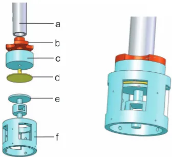
FIG. 2. (Right) Plastic magnetometer. (Left) The two assemblies that form the magnetometer: the rod assembly includes (a) hollow stainless steel rod from the mixing chamber to the center of the magnet, (b) oxygen free copper adapter, (c) threaded Tufset piece, and (d) top plate of the capacitor made of brass. The magnetometer assembly is entirely made of Tufset and includes (e) sample holder+movable capacitive plate and (f) body.
We chose to build the magnetometer out of plastic (Tufset–Tufnol Composites Limited) with the main purpose of avoiding eddy current heating during the magnetic field sweeps. For maximum simplicity, it consists of two assem-blies, each of them containing one plate of the sensor capac-itor. The first one (pieces (a)–(d) in Figure2), which hosts the fixed capacitance plate, includes the rod (piece (a)) lead-ing from the mixlead-ing chamber of the dilution refrigerator to the centre of the magnet. The second one includes the mag-netometer assembly containing two pieces: a body (piece (f)) that screws into the first assembly, and a sample holder (which includes the movable capacitor plate) suspended by wires (piece (e)). For this small design we inverted the geometry from Ref.5by placing the movable capacitor plate above the sample holder as depicted in Figure2. In this way, the magne-tometer assembly screws into the probe rod, allowing control over the initial capacitance.
The magnetometer body consists of a hollow cylinder of 20 mm outer and 18 mm inner diameter, machined out of a single piece of Tufset. Four windows were made to allow easy access to the sample holder that sits in its centre.
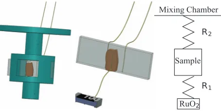
The sample holder is also machined out of a single piece of Tufset. We painted the capacitor plate on it (Figure3) with room temperature air-cured silver paste (4929N, DuPont) and then linked it to a connector on the magnetometer body with a 25μm diameter gold wire. The sample space on this piece is 4 mm by 3 mm and 8 mm in depth. This space is divided into two by a sapphire plate of thickness 0.2 mm that slides into a perpendicular slot and is fixed with vacuum grease (Apiezon N), leaving effectively a sample space of 4 mm in depth (left of Figure3). The sapphire acts as an orientation plane for the sample that is attached to it with vacuum grease as shown in the central part of Figure3.
[image:3.612.63.284.570.718.2]Sample
RuO Mixing Chamber
FIG. 3. (Left) Sample holder with sapphire plate and sample. (Centre) Detail of the sapphire plate. Gold wires at the back of it are used to thermalise the sample that is greased to the front of the plate. The sample is connected by another gold wire to a RuO2thermometer hanging from the magnetometer body by its contacts. (Right) Thermal resistance diagram,R1is much lower thanR2.
threaded, the lines are glued in position with epoxy (#1266, Stycast). These lines provide the restoring force for the mov-ing plate of the capacitor, and the choice of material and ge-ometry is vital to define the sensitivity of the magnetometer.
Given the constraints in our case, we chose to design a small magnetometer that would not need the use of a centering mechanism. This reduces the theoretical sensitivity, which for a simple model of the deflection of a beam is proportional to
L3, withLthe length of the wires from the inner diameter to
the sample holder at the centre.7 We partially compensated
this by the choice of nylon fishing line, which in addition of being non-metallic, has a low elastic constant.
Thermal anchoring of the sample is achieved through two 25μm gold wires of negligible spring constant. These wires link a connector on the magnetometer body with the back of the sapphire plate, where they are bonded with silver paste (6838, Dupont). Finally, a thick 0.5 mm silver wire thermally grounds the connector to the mixing chamber. In this way, the sapphire plate is the main thermal link between the sample and the mixing chamber.
In order to measure the temperature of the sample, we attached with silver paste a 25μm gold wire from the sample to the back of a bare 1 kRuO2 chip (crg0805 smt, Tyco
Electronics). In this way we obtained a much lower thermal resistance between the sample and the thermometer,R1, than
between the sample and the mixing chamberR2(see Fig.3).
For efficient setup of the experiment, it is desirable to tune the initial capacitance at room temperature. This is achieved by screwing the body assembly into the rod as-sembly. To avoid twisting wires during this process, there are connectors on the magnetometer body assembly for all wires coming from the stainless steel rod, namely the man-ganin thermometer wires, the miniature co-axial cable (type SS, Lakeshore) and the thermal link to the mixing chamber.
IV. EXPERIMENTAL RESULTS
We tested the performance of our magnetometer on two systems with very different characteristics: one is the frus-trated magnet Dy2Ti2O7, an insulator with large magnetic
mo-ments which shows strong out of equilibrium magnetisation jumps below 650 mK in low magnetic fields (below 1 T).9
Here, the simultaneous measurement of the sample tempera-ture is invaluable for understanding the non equilibrium pro-cesses. The other system is Sr3Ru2O7, a strongly correlated
paramagnetic metal with a series of metamagnetic jumps of approximately 0.1μB/Ru between 7.5 and 8.5 T,14on which
we could test the performance of the magnetometer up to magnetic fields of 15 T.
A. Magnetisation and temperature measurements on Dy2Ti2O7
We tested the low magnetic field performance of our magnetometer on the frustrated magnet Dy2Ti2O7, a
cooper-ative paramagnet of the spin-ice family.8 The magnetic
mo-ments come from Dy ions residing on the vertices of a py-rochlore lattice; because of strong single ion anisotropy, the ground state of the Dy3+can be thought as an Ising doublet with local quantisation axis along the111crystallographic axis. The combination of lattice geometry, exchange and a dipolar interaction arising from the very large Dy magnetic moments (approximately 10μB) results in a frustrated ground
state with a degeneracy growing exponentially with the size of the system. A freezing transition occurs at about 650 mK, below which the system develops out-of-equilibrium dynam-ics for any experimentally achievable time. A detailed study of the phenomena can be found in Ref.9.
A single crystal of Dy2Ti2O7 was grown by the
float-ing zone method in St Andrews University, Laue oriented and cut into a prism of∼2×0.7×0.5 mm3with the long axis
along [111]. The sample was mounted on the sapphire plate as explained in Figure3, with [111] parallel to both the mag-netic field and its gradient. The free load capacitance (no ap-plied gradient) in this experiment was 7.2 pF. The magnetic field and temperature were controlled from a PC which also records the capacitance measured with an automatic capaci-tance bridge operating at 1 kHz (2500 A, Andeen–Hagerling). This bridge and a resistance bridge (SIM 921AC, Stanford Research Systems) which measures the RuO2 thermometer
on the sample were set to give a data point per second. Ex-ternal vibrations were damped by placing the cryostat dewar on the platform of an active vibration-isolation system (vario 45/60/90, Halcyonics). The main magnet field was swept at constant rate while the gradient coils are fixed with a constant value of∼1 T/m. The measurements were calibrated by com-paring the magnetisation vs. field curves at 4 K with those taken in a squid magnetometer (quantum design MPMS).
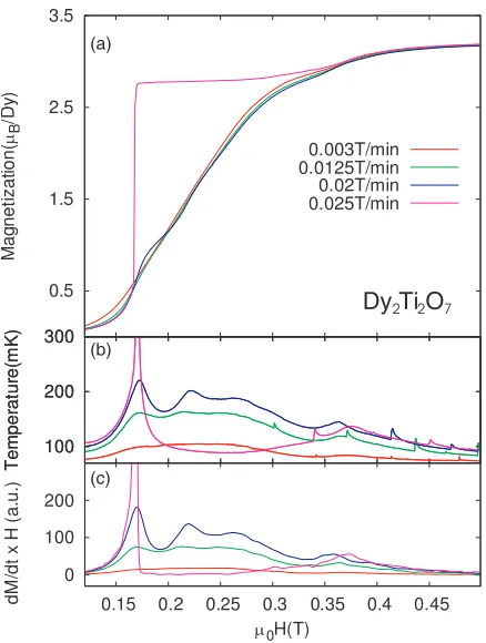
Figure4(a)shows the raw data for the low field part of the magnetisation curve at base temperature (∼80 mK) for differ-ent sweep rates. The resolution on these curves is better than 1×10⁻⁵emu. The out-of-equilibrium behaviour of this co-operative paramagnet can be inferred from the dependence of the magnetisation on the sweep rate. For slow sweep ratesM
follows a smooth curve which becomes increasingly undulat-ing as the sweep rate is increased, until it eventually becomes discontinuous with a very sharp jump of about 50% of the sat-uration value (of 5μB/Dy for this orientation10). Panel (b) of
[image:4.612.60.287.53.167.2]125104-4 Slobinskyet al. Rev. Sci. Instrum.83, 125104 (2012)
Dy
(a)(b)
(c)
Ti O
2 2 7FIG. 4. (a) Magnetisation vs. magnetic field of Dy2Ti2O7for different sweep rates measured with the cryostat at base temperature (Tmch ∼ 80 mK).
(b) Sample temperature vs. magnetic field, as measured from the RuO2 ther-mometer simultaneously with the magnetisation shown in (a). The small spikes above 0.3 T are spurious effects due to spikes in the external mag-netic field (caused by flux jumps in the main coil of our magnet) resulting in small temperature changes. (c) Derivative of the magnetisation with respect to time multiplied by the magnetic field (i.e., rate of heat generation) as a function of magnetic field.
Our capability of measuring temperature allows a simple thermal analysis that gives insight into the underlying physics. The sample is strongly thermally coupled to the mixing cham-ber; so changes in the sample temperature are proportional to the power being dissipated in the magnetisation process (see below). This can be seen comparing the temperature in panel (b) with panel (c), where the heat produced in the process per unit volume and unit time,μ0H·d(dμM
0H)×field sweep rate, is plotted as obtained from the data in panel (a).
To analyse the temperature data more rigorously one can do a simple thermal modelling of the system. The production and diffusion of heat from the sample to the mixing cham-ber is ruled by the continuity equation: du
dt + ∇ ·J=w(t,r), wereuis the internal energy of the crystal per unit volume,
Jis the heat density current, andw(t,r) is the heat delivered locally to the lattice per unit volume and unit time. Due to the way we designed the probe and thermally anchored the sample, it is reasonable to assume that the delivered magnetic energy either remains within the sample, raising its tempera-tureT(t), or flows towards the mixing chamber of the cryo-stat, building up a total heat currentIth(t). Integrating the
con-tinuity equation over the volume of the sample, and using Fourier’s law to expressIth, we can write
Cp
dT
dt =1/Rth(T(t)−Tmch)+V μ0H· dM
dt , (2)
whereT(t)−Tmchis the difference between the temperature
of the sample (directly measured by our thermometer) and that of the mixing chamber;Rth is the thermal resistance of
the link between these two points,Cpthe specific heat of the
sample, andV its volume.
The specific heat of Dy2Ti2O7 is very small in the
re-gion of parameters of Figure 4 (see Ref. 11), implying a very short relaxation time (in the scale of our measurements). This means that the left hand side of (2) can be neglected with respect to any of the terms in the right, which tend to balance each other. The sample is then in a quasi-stationary state (CpdTdt ≈0) at all times, giving the proportionality mea-sured between Figs.4(b)and4(c):T =Tmch+Rthμ0H· ddtM. In practice, it was then possible to identify the microscopic process as a release of Zeeman energy during the out-of-equilibrium processes.
B. Magnetisation measurement on Sr3Ru2O7
The ruthenate Sr3Ru2O7was used to test the performance
of the probe at high fields and to test the method of gradient field modulation to measure susceptibility. At low tempera-tures, Sr3Ru2O7 is a paramagnetic Fermi liquid that
under-goes a set of meta-magnetic first order transitions as a func-tion of magnetic field. These transifunc-tions occur below∼1.2 K and in the neighbourhood of 8 T for field aligned close to the crystallographic c-axis. This material also provides a valuable test for the mechanical stability of the magnetometer given that for slight misalignments from the c-axis the magnetisa-tion as a funcmagnetisa-tion of field lacks a feature around 12 T that is seen in torque measurements.12
We used the same experimental setup than in the case of Dy2Ti2O7 and measured a single crystal of Sr3Ru2O7 of
dimensions 2.4×2.5×1.2 mm3. The free-load capacitance
was of 26 pF, and the sample sat between 5◦ and 10◦off the c-axis, as inferred from the known dependence of Hc with
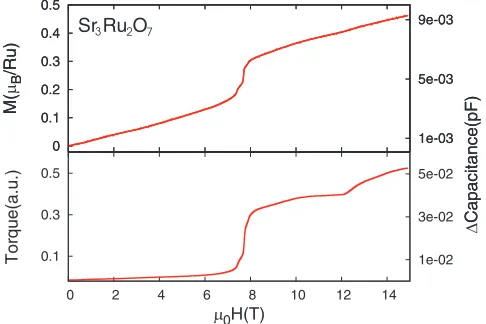
angle13,14). The raw signal was approximately quadratic in nature and of even parity with respect to the applied magnetic field. Given that the system is a well known paramagnet, this is contrary to the naive expectation of an odd signal as a func-tion of applied magnetic field. This change in field parity is the consequence of a large torque component. To isolate each contribution we measured sets of data both with positive and negative field gradient: the magnetisation was extracted as the semi-sum of these data, while torque was the semi-difference. The torque and magnetisation signals are shown in Figure5. Notice that, in accordance with Ref.12, there is a very notice-able feature in the torque signal at about 12 T which is almost completely absent from the magnetisation curve. In another experiment with an initial capacitance of about 2.6 pF the raw data still showed a quadratic shape but with a much less pro-nounced behaviour.15Independent of the setup conditions, the subtraction and addition of the signals with positive and nega-tive gradient fields has proven to give the right magnetisation and torque in all cases. However, the subtraction and addition reduce the sensitivity by up to an order of magnitude.
Using the same sample of Sr3Ru2O7 we tested the idea
[image:5.612.65.284.49.339.2]0.1 0.3 0.5
0 2 4 6 8 10 12 14
1e-02 3e-02 5e-02 Torq u e(a. u .) 0H(T) 0 0.1 0.2 0.3 0.4 0.5 1e-03 5e-03 9e-03 M( B /R u ) Capacitance(pF) 0 0.1 0.2 0.3 0.4 0.5 1e-03 5e-03 9e-03 M( B /R u ) Capacitance(pF)
Sr Ru3 2O7
FIG. 5. (Top) The magnetisation of Sr3Ru2O7, antisymmetric part of the raw signal with respect to the magnetic field gradient, extracted from the difference of sweeps with positive and with negative field gradient. (Bottom) Symmetric part, giving the torque. The right-hand side axis is proportional to the raw signal. Note that torque signal is almost an order of magnitude bigger than that for the magnetisation for this starting capacitance of 26 pF.
susceptibility. For this, we replaced the automatic capacitance bridge by a manual capacitance bridge (1616, General Radio) to which we connected two lock-in amplifiers (LIA) in series (SR830, Stanford Research Systems). The capacitor was ex-cited with a frequency of 1 kHz and the signal measured with the first LIA. The second LIA drove the gradient coils at a low excitation frequencyνDthrough a commercial hi-fi amplifier.
The analogue channel output signal of the first LIA was fed as the input of the second LIA from where the signals atνD
in the first and second harmonics were detected.
Figure 6 shows the real part of the susceptibility mea-sured at νD = 3 Hz around the meta-magnetic transitions.
These data have signal-to-noise ratio comparable to previ-ously reported field modulated susceptibility data,14 where
low-temperature transformers had been used to boost the
0 0.01 0.02 0.03 0.04 0.05 0.06 0.07
6.6 6.8 7 7.2 7.4 7.6 7.8 8
S u scepti b ility(a. u .)
µ0H(T) 50mK
150mK
300mK 700mK500mK 0 0.01 0.02 0.03 0.04 0.05 0.06 0.07
7.6 7.65 7.7 7.75 7.8
Sr R3 u2O7
FIG. 6. Gradient modulation susceptibility at 3 Hz for different temperatures around the meta-magnetic transitions of Sr3Ru2O7. Three main peaks can be seen with a noise comparable to the one on Ref.14. Inset: blow up of the main peak.
signal. This technique is most useful to measure susceptibil-ity when the frequencies are too low to give a good inductance signal, and is in principle limited in frequency by the mass of the sample stage. The range of frequencies could, in principle, be extended by employing feedback to measure while keeping the capacitor plates static.
V. CONCLUSIONS
We presented a newly designed plastic magnetometer with a resolution better than 10−5emu capable of operating at millikelvin temperatures and under magnetic fields up to 15 T. The magnetometer was successfully integrated with a sample thermometer that measures the instantaneous change in temperature of the sample with high accuracy down to tem-peratures of approximately 50 mK. We demonstrated the pos-sibility of extracting the torque signal from the raw signal and confirmed that the latter grows with the initial equilibrium ca-pacitance. Furthermore, we showed that the same probe can be used to measure the magnetic susceptibility by modulat-ing the gradient field at low frequencies, for which the usual inductive methods yield a very low signal.
ACKNOWLEDGMENTS
We wish to thank to E. A. Yelland, J. A. N. Bruin, and A. W. Rost for helpful discussions and for their help in the lab, and R. S. Perry and A. S. Gibbs for providing the crystals for the experiments. This work was done with the financial sup-port of EPSRC and the Royal Society (UK) and CONICET (Argentina). A.P.M. acknowledges the receipt of a Royal So-ciety Wolfson Research Merit Award.
1S. Foner,Rev. Sci. Instrum.30, 548 (1959).
2S. Legl, C. Pfleiderer, and K. Krämer,Rev. Sci. Instrum.81, 043911 (2010). 3Strictly,F= ∇(μ·B).
4A. G. Swanson, Y. P. Ma, J. S. Brooks, R. M. Markiewicz, and N. Miura,
Rev. Sci. Instrum.61, 848 (1990).
5T. Sakakibara, H. Mitamura, T. Tayama, and H. Amitsuka,Jpn. J. Appl.
Phys.33, 5067 (1994).
6J. S. Brooks, M. J. Naughton, Y. P. Ma, P. M. Chaikin, and R. V.
Chamberlin,Rev. Sci. Instrum.58, 117 (1987).
7See for example, L. D. Landau and E. M. Lifshitz,Theory of Elasticity, 2nd
ed., Course of Theoretical Physics (Pergamon, 1981).
8For a review on spin-ice see S. T. Bramwell and M. J. P. Gingras,Science
294, 1495 (2001).
9D. Slobinsky, C. Castelnovo, R. A. Borzi, A. S. Gibbs, A. P. Mackenzie,
R. Moessner, and S. A. Grigera,Phys. Rev. Lett.105, 267205 (2010). 10T. Sakakibara, T. Tayama, Z. Hiroi, K. Matsuhira, and S. Takagi,Phys. Rev.
Lett.90, 207205 (2003).
11R. Higashinaka, H. Fukazawa, K. Deguchi, and Y. Maeno,J. Phys. Soc.
Jpn.73, 2845 (2004).
12E. Ohmichi, Y. Yoshida, S. I. Ikeda, N. V. Mushunikov, T. Goto, and
T. Osada,Phys. Rev. B67024432 (2003).
13S. A. Grigera, R. A. Borzi, A. P. Mackenzie, S. R. Julian, R. S. Perry, and
Y. Maeno,Phys. Rev. B67, 214427 (2003).
14S. A. Grigera, P. Gegenwart, R. A. Borzi, F. Weickert, A. J. Schofield,
R. S. Perry, T. Tayama, T. Sakakibara, Y. Maeno, A. G. Green, and A. P. Mackenzie,Science306, 1154 (2004).
15Higher initial capacitances amplified torque signals quadratically with
[image:6.612.53.296.55.217.2] [image:6.612.65.284.509.661.2]