An electrically tunable single-photon source
triggered by a monolithically integrated
quantum dot microlaser
Pierce Munnelly,
†Tobias Heindel,
†Alexander Thoma,
†Martin Kamp,
‡Sven
Höing,
‡,¶Christian Schneider,
‡and Stephan Reitzenstein
∗,††Institut für Festkörperphysik, Technische Universität Berlin, 10623 Berlin, Germany
‡Technische Physik, Universität Würzburg, 97074 Würzburg, Germany
¶School of Physics and Astronomy, University of St Andrews, St Andrews KY16 9SS,
United Kingdom
E-mail: [email protected]
Abstract
We report on a quantum dot micropillar-based single-photon source demonstrat-ing tunable emission energy via an applied electric eld and driven by an on-chip, whispering-gallery-mode microlaser. The cavity-enhanced single-photon source is mono-lithically integrated with an electrically driven, coherent excitation source. The device
concept features low laser-threshold currents of a few tens of µA, has a small
foot-print with a device area of∼200µm2and demonstrates high single-photon purity with
g(2)(0) as low as 0.07±0.03 under pulsed electrical excitation of the microlaser. The
electric eld applied along the growth direction of the single-photon emitter allows the
emission to be tuned by up to1.1meV via the quantum-conned Stark eect, bringing
Keywords
Semiconductor Quantum Dot, Whispering-Gallery-Mode Laser, Single-Photon Source, Pho-tonics, Integrated Quantum Optics
Quantum dots (QDs) in the solid-state are well-suited for on-demand production of sin-gle photons, which themselves are of great interest for quantum information processing,
communication and metrology.1,2 Two withstanding challenges for successful applications of
QD-based single-photon sources (SPSs) are integration with other photonic elements and control over the emission properties.
Regarding integration, directional and enhanced luminescence from QDs has been
suc-cessfully achieved by, for instance, coupling to waveguides,3 nano-antennae,4,5 nanowires,6
microlenses7 and micropillar cavities.8,9 In particular, the GaAs platform has proven to be
appropriate in many ways for photonic integration.10 Furthermore, the requirement of
in-distinguishability necessary for quantum technologies relying on single-photon interference
and entanglement distribution will best be met with resonant excitation schemes.1113 In the
interest of compactness and scalability, electrical carrier injection would be highly attractive - avoiding bulky external laser sources. However, simple electrically driven sources based on a pin-diode design do not allow for resonant excitation and suer from charge noise intro-duced by excess carriers, both of which limit the indistinguishability of the emitted photons. A possible solution to this problem is the integration of an optical excitation source on the same chip, which is itself electrically triggered, spectrally narrow and allows for resonant
excitation of the target single-photon emitter as we proposed and demonstrated in Ref.14
Regarding control of the QD emission energy, this has commonly been achieved in one
of three ways: temperature tuning,8 which exploits the temperature dependence of the
bandgap; piezo-electric strain tuning,15which relies on the built-in polarization of the matrix
material to modify the energy levels of the emitter via the quantum-conned Stark eect
(QCSE); and by direct application of an electric eld,16 which also modies the emission
of separate photonic elements which rely on a constant refractive index, such as waveguides;
strain tuning has made great progress in recent years15,17 but requires either complicated
processing steps or large piezo-actuators which again limit scalability. It seems the most desirable tuning mechanism would be able to tune the emitters with minimal fabrication complexity and in a localized way that does not interfere with other integrated elements. QCSE via an applied electric eld is an ideal mechanism for this, showing large tuning ranges
and tuning areas limited by the contact size.1822
Monolithic integration of QDs with coherent, electrically controlled
whispering-gallery-mode (WGM) lasers has recently been pursued.23This work represents a major advancement
in this direction by bringing multiple aspects of desirable functionality, including integration and electrical control, together on a single chip as well as very pure single-photon emission.
Methods
The monolithically integrated microlaser and electrically tunable SPS consist of pin-doped QD-based micropillars grown by molecular beam epitaxy on an n-doped GaAs substrate. A
single layer of InGaAs quantum dots (areal density3×109cm−2) embedded within aλ-cavity
form the active material for WGM lasing in the larger of the two micropillars, henceforth referred to as the microlaser. The same QD layer provides the single-photon emitters in the smaller of the two micropillars, henceforth referred to as the SPS-micropillar; for fabrication
details see Ref.23 The fundamental pillar mode is spectrally detuned from the QD ensemble
to the red side of its maximum by ∼ 50meV, which results in a spectral density of about
one excitonic line per meV in the spectral vicinity of the cavity mode facilitating single QD studies. The device characterized here has an optimized number of distributed-Bragg
reector (DBR) pairs of 13above and26 below the cavity for the best compromise between
brightness and Purcell enhancement in the SPS.24 The microlaser and SPS-micropillar are
p-contacts for electrical control. The micropillars share the same n-contact on the back side, but have isolated p-contacts allowing for the individual control of the current injected into the microlaser or the bias-voltage applied to the SPS-micropillar. The optical excitation power incident on the SPS-micropillar can be controlled via the continuous injection current or voltage pulse height applied to the microlaser. Monolithic integration allows for nanometer
precision in the distance between the microlaser and the SPS-micropillar (15µm), resulting
in controlled and stable coupling of the structures. The p-contact on the SPS-micropillar has an aperture for the vertical emission of single-photons in the DBR mode perpendicular to the emission plane of the WGM microlaser. The ring aperture provides lateral current injection and has no observable eect on the single-photon outcoupling eciency for this
pillar diameter. The total device area including pads for bond wires is ∼200µm2.
We investigated two devices each consisting of a microlaser and SPS-micropillar pair, referred to as device A and device B. The devices were characterized in a continuous-ow
liquid-helium cryostat with a micro-photoluminescence (µPL) spectroscopy setup using a
microscope objective NA of 0.42 (detection spot ∼ 3µm in diameter) and having a
spec-tral resolution of 100µeV. Single photons are vertically emitted from a QD in the
SPS-micropillar directly into the detection axis when the microlaser is electrically driven by a source-measurement unit, and the orthogonal microlaser emission is vertically scattered from nearby uncontacted walls, giving access to the laser mode optical characteristics. For time-resolved (TR) measurements, a voltage pulse generator with a variable repetition rate of
up to 250MHz was used to trigger the microlaser with pulse amplitudes as high as 3V
and a variable DC oset. TR measurements were carried out on the microlaser and SPS-micropillar emission using an silicon-based single-photon counting module (SPCM) with a
timing resolution of250ps and time-correlating electronics triggered by the pulse generator.
For measurements of the photon autocorrelation function g(2)(τ), two SPCMs together with
a 50/50 ber-beamsplitter were used with the timing electronics in an Hanbury-Brown and
control the temperature of the devices from 5−40K.
Results
4 0 6 0 8 0 1 0 0 1 0 0
2 0 0 3 0 0 4 0 0
1 . 4 2 5 1 . 4 5 0 1 . 4 7 5 1 . 3 7 1 . 3 8
a
1 5 µm
W G M - M i c r o l a s e r S P S - M i c r o p i l l a r p - c o n t a c t
L a s e r E m i s s i o n
I n G a A s Q D s
A p e r t u r e S i n g l e P h o t o n s
C u r r e n t (µA )
I
t h r = 7 6 µA
In t. In te n s ity ( a .u .) F W H M ( µ e V ) b In te n s it y ( a .u .)
E n e r g y ( e V ) W G M - M i c r o l a s e r
c In te n s it y ( a .u .)
E n e r g y ( e . V . )
d
S P S -M i c r o p i l l a r
F P M
[image:5.612.198.405.163.347.2]X
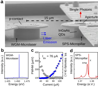
Figure 1: Sample layout and optical characterization of device A at 30K. (a) An SEM
image of a 6µm-diameter whispering-gallery-mode (WGM) quantum dot (QD) microlaser
monolithically integrated next to a 2µm-diameter single-photon-source (SPS) micropillar.
The QD is resonantly coupled to the fundamental pillar mode (FPM) and emits single photons vertically through the aperture in the contact, which have been created by the microlaser's horizontal excitation. (b) A spectrum of the microlaser emission above threshold showing single-mode lasing. (c) Integrated intensity (lled blue circles) and full-width at half-maximum (FWHM, open black circles) of the laser mode emission plotted against injection
current. The tted laser-threshold current is 76µA (grey line). (d) A spectrum of the
neighboring SPS-micropillar under strong microlaser excitation. The FPM and a bright,
single-QD excitonic transition (X) can be seen at 1.376eV.
We rst present an overview of the device layout and optical characteristics of device A
at30K. Fig. 1(a) shows a scanning-electron microscope (SEM) image of the integrated SPS.
A larger micropillar with a diameter of6µm acts as a microlaser via WGM emission in the
plane of the QD active layer, and this laser emission pumps a single QD in the cavity of the
neighboring SPS-micropillar of smaller diameter (2µm). While the laser emission is isotropic
in the horizontal plane, the single photons emitted from the excited QD are highly directional along the vertical axis through the aperture. As mentioned in the previous section, the
normal operation, but this polymer has been ashed away in this gure to better reveal the underlying micropillar and contact structure. The radial separation between the micropillar
and the microlaser is 15µm. The gold p-contact seen overhanging the micropillar serves
two crucial purposes: a bias can be delivered to the contact which tunes the emission of the QD via the QCSE, and an aperture in the contact suppresses the unwanted stray laser emission in the desired single-photon emission. The SPS-micropillar bias-voltage is isolated from the laser bias-voltage by the separate p-contact layout. To optically characterize the laser emission, we focus the microscope objective on nearby uncontacted walls as seen in the background of Fig. 1(a), which scatter laser light into the vertical direction. Fig. 1(b) shows
a typical spectrum of the single-mode microlaser driven above threshold at130µA. Fig. 1(c)
shows the intensity input-output curve of the laser mode emission (blue solid circles) and the full-width at half-maximum (FWHM, black open circles) as collected with the spectroscopy setup and tted using a Voigt function. Lasing is evidenced by the drop in FWHM to the setup resolution and the sudden increase in mode intensity. The laser threshold current is
determined with a linear t to the integrated intensity (grey line) and is found to be 76µA.
A spectrum of the SPS-micropillar as it is driven by the microlaser under strong excitation
is shown in Fig. 1(d). Here we see the fundamental pillar mode (FPM) at 1.376eV and a
bright excitonic transition (X) slightly detuned to the blue side of the FPM. Here there is no external bias applied to the target SPS-micropillar. The FPM is spectrally detuned from
the laser mode by ∼80meV, and the laser provides wetting-layer excitation to X.
We now turn our attention to the electro-optical tuning of an exciton X from the SPS-micropillar in device A, performed with a varying bias-voltage applied at the aperture con-tact, and compare this to the case of temperature tuning of the same X over the same energy range. Fig. 2(a) shows an intensity plot of X driven by the microlaser as the bias-voltage on
the SPS-micropillar is varied from0.5−1.3V. The temperature is held constant at33K and
the microlaser is driven with a constant current of90µA. X is tuned over an absolute energy
0 . 5 0 . 6 0 . 7 0 . 8 0 . 9 1 . 0 1 . 1 1 . 2 1 . 3 1 . 3 7 5 0
1 . 3 7 5 5 1 . 3 7 6 0 1 . 3 7 6 5 1 . 3 7 7 0
B i a s ( V )
E n e rg y ( e V ) 0 1
F P M
X
3 3 K
In te n s ity ( a .u .) In te n s ity ( a .u .)
2 8 3 0 3 2 3 4 3 6 3 8
1 . 3 7 5 0 1 . 3 7 5 5 1 . 3 7 6 0 1 . 3 7 6 5 1 . 3 7 7 0
T e m p e r a t u r e ( K )
E n e rg y ( e V ) 0 1
F P M B i a s = 1 . 1 V
X
1 0 0 0 8 0 0 6 0 0 4 0 0 2 0 0 0
- 2 0 0 - 1 0 0 0 1 0 0 2 0 0 3 0 0
R e l a t i v e D e t u n i n g ∆(µe V )
a
b
[image:7.612.205.413.213.518.2]R e l a t i v e D e t u n i n g ∆(µe V )
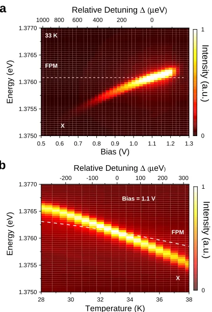
Figure 2: A single exciton (X) pumped by the integrated WGM microlaser in device A. (a)
Electro-optical tuning of X through the FPM via an applied bias at 33K and laser current
levels of the QD but leaves the energy of the FPM unchanged,20 and X is electro-optically
tuned into resonance with the FPM at a bias of 1.1V. Purcell enhancement as well as a
gradual increase in intensity due to attening of the built-in potential, which reduces
tun-neling of the charge carriers out of the QD, can both be seen.20 The intensity of X abruptly
quenches at ∼ 1.25V, most likely due to a nearby trap becoming resonant with X
provid-ing a faster, non-radiative recombination channel. For comparison, Fig. 2(b) shows X at
a constant bias of 1.1V being temperature-tuned through resonance with the FPM under
the same excitation conditions and over the same absolute energy range of 1.1 meV. The
relative detuning between X and the FPM emission energy∆ = EFPM−EX is shown in the
top axes of the intensity plots for both methods of tuning, and a crucial dierence can be
seen: the maximum relative detuning ∆ for the electro-optical case is 820µeV. In contrast,
by temperature tuning X over the same 1.1meV absolute energy range corresponding to a
temperature increase of10K, the relative detuning between X and the FPM is320µeV. This
is because heating simultaneously red-shifts X and the FPM, making the relative tunability between the two much smaller than in the case of electro-optical tuning. This becomes
im-portant when one considers that the FWHM of the FPM is a factor ∼10greater than that
of X, meaning a larger tunability is useful if Purcell-enhanced emission is to be achieved. In addition to the points raised in the introduction about scalability, this is another advantage of an applied electric eld as a tuning mechanism.
The electro-optically tuned SPS-micropillar emission properties of device A are exam-ined in closer detail in Fig. 3. Two spectra showing X in and out of resonance with the FPM are shown in Fig. 3(a). The detuning between X and the FPM is out of the range shown in the color plot of Fig. 2(b), but the excitation conditions and bias are the same.
The microlaser is operated at 90µA in both cases and the resonance temperature is 33K.
The FWHM of X in resonance is 140µeV, which is much larger than typical linewidths for
InGaAs QDs.25 This is because the ne-structure splitting between horizontal and vertical
- 2 0 - 1 0 0 1 0 2 0 0 . 0
0 . 5 1 . 0
- 6 0 0 - 4 0 0 - 2 0 0 0 2 0 0 4 0 0 6 0 0 0 . 0
0 . 5 1 . 0
1 . 3 7 4 1 . 3 7 6 1 . 3 7 8
0 5 1 0 1 5
g
(2
)(τ
)
D e l a y τ ( n s ) g ( 2 )
d e c o n v( 0 ) = 0 . 3 9 ± 0 . 1 4
In te g ra te d I n te n s it y ( a .u .)
D e t u n i n g ∆(µe V ) F P u r c e l l = 2 . 2 ± 0 . 4
b In te n s it y ( a .u .)
E n e r g y ( e V )
∆ =
- 5 6 0 µe V
∆ = 0
X
F P M
c
In te n s it y ( a .u )T i m e ( n s ) L a s e r X
t 1 = 4 8 6 p s
a
[image:9.612.201.414.207.471.2]d
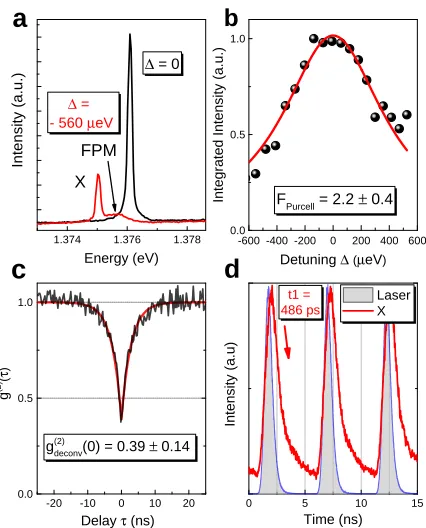
Figure 3: Emission properties of the electro-optically tuned X in device A at1.1V bias. (a)
Two spectra showing X and the FPM in and out of resonance at33K and42K, respectively.
(b) The tted Purcell factor for the temperature tuning of X is 2.2±0.4. (c) Non-classical
light emission of X at 33K under constant laser excitation is veried by the tted value of
g(2)(0) = 0.41±0.14 and the deconvoluted value of g(2)
deconv(0) = 0.39±0.14. (d)
Time-resolved measurements show the microlaser pulses (grey lled curves) have an FWHM of
is 100µeV, the individual transitions themselves are resolution-limited. The emission of X is enhanced by the Purcell eect when the FPM and X spectrally overlap. The integrated
intensity of X over a temperature range of18K was tted in Fig. 3(b) using the t function
in Ref.26From this t, a Purcell factorF
P = 2.2±0.4is extracted. To verify the non-classical
nature of the cavity-resonant emission of X under constant microlaser excitation, the light was analyzed with the HBT-setup as shown in Fig. 3(c). The characteristic dip at
zero-delay in the autocorrelation function which falls below0.5is proof that X is a single-photon
emitter driven by an integrated microlaser, with a raw tted value of g(2)(0) = 0.41±0.14.
A deconvolution of the signal accounting for the nite time-resolution of the SPCMs yields
g(2)
deconv(0) = 0.39±0.14. Here, the non-ideal QD-lifetime is explained by the illumination of
the cavity mode by non-resonant spectator QDs and the associated uncorrelated background emission. The time-resolved measurement of the lifetime of X in resonance with the FPM
under pulsed microlaser excitation at 190MHz is shown in Fig. 3(d). The lifetime extracted
from an exponential t was found to be (486±42)ps, which is about a factor 2.5 smaller
than the typical value of 1.2ns for these quantum dots in the absence of the upper DBR.
This agrees well with the tted Purcell factor (FP = 2.2±0.4) of Fig. 3(b). This decay time
is however clearly shorter than that suggested by the width of the anti-bunching dip in the
continuous measurement of g(2)(τ) shown in g. 3(c), which indicates that the width of the
dip in g. 3(c) is limited by slow lling processes of the QD at a timescale longer than the QD lifetime. The laser pulses themselves, represented by the lled grey curves coinciding
with X, have an FWHM of 780ps and a decay time of 343ps. This is promising with
re-spect to on-demand resonant excitation of these QDs, as the laser pulse decays faster than the QD. Furthermore, Fabry-Pérot spectrometer measurements (not shown) reveal FWHMs
< 2µeV typical for these microlasers at currents of ∼ 100µA, which is on the same order
- 3 0 - 2 0 - 1 0 0 1 0 2 0 3 0 - 3 0 - 2 0 - 1 0 0 1 0 2 0 3 0 - 3 0 - 2 0 - 1 0 0 1 0 2 0 3 0 C o in c id e n c e s ( a .u .)
D e l a y
τ
( n s )g ( 2 )( 0 ) = 0 . 2 6 ± 0 . 1 1 H B T 1 9 0 M H z
C o in c id e n c e s ( a .u .)
D e l a y
τ
( n s )g ( 2 )( 0 ) = 0 . 0 7 ± 0 . 0 3 H B T 1 6 4 M H z
c
D e v i c e B
D e v i c e A D e v i c e B
C o in c id e n c e s ( a .u .)
D e l a y
τ
( n s )V i s i b i l i t y = ( 2 2 ± 3 ) %
a
b
[image:11.612.156.451.225.465.2]H O M 1 6 4 M H z
Figure 4: Pulsed, second-order correlation functionsg(2)(τ)measured in the Hanbury-Brown
Twiss (HBT) congurations. (a) The electro-optically tuned X of device A, in resonance
with the FPM under a bias of1.1V, is pulsed by the WGM microlaser demonstrating
single-photon emission with g(2)(0) = 0.26±0.11 at 33K. (b) Device B demonstrating very pure
single-photon emission withg(2)(0) = 0.07±0.03in resonance with the FPM at5K and with
Fig. 4(a) shows a measurement of g(2)(τ) on the X of device A, again with the 1.1V
bias and in resonance with the FPM at 33K, but now under pulsed microlaser excitation.
The pulse repetition rate was 190MHz. A t to the peak areas gives a value of g(2)(0) =
0.26± 0.11, clearly below 0.5 and representative of a truly single-photon emitter. One
reason for the improvement of the measured single-photon purity under pulsed excitation compared to constant excitation is because in the former case, the threshold of the laser is reduced, and this in turn reduces the background emission of the laser relative to the lasing mode intensity. The gain spectrum of the microlaser is given by the homogeneously
broadened QD-distribution, which has a Gaussian FWHM of 30meV. Therefore the tail
of the gain spectrum which overlaps with the FPM of the SPS-micropillar is reduced under
pulsed excitation, and the eect of stray laser background light in the measurement ofg(2)(τ)
is reduced. In Fig. 4(b) we present g(2)(τ) data of another SPS-micropillar driven by an
integrated, low-threshold, single-mode microlaser (device B, on the same chip). This device
demonstrates better performance in terms of a greatly reducedg(2)(0) = 0.07±0.03because
of reduced impact of uncorrelated emission of spectator QDs, but this excitonic transition was not tunable via an electric eld as device A was, most likely due to the weak connement of charge carriers typical in these quantum dots. The excitonic transition X for device B was
in resonance with the FPM of a 2.7µm-diameter micropillar at 5K, with no bias applied at
the SPS-micropillar contact.
Conclusion
The results presented in this letter demonstrate the operation of QD-based, electrically
triggered single-photon sources that show high purity (g(2)(0) as low as 0.07±0.03) and are
driven by low-threshold microlasers integrated on the same chip. Electro-optical tuning of
a single-QD exciton via an applied bias is demonstrated over a 1.1meV energy range. The
by the larger relative detuning between the cavity mode and the exciton, as well as being a tuning mechanism that is localized to the dimensions of the micropillar. The cavity-enhanced emission in resonance with the fundamental mode of the micropillar reduces the lifetime of
the emitter by more than half with a Purcell factor of 2.2±0.4. The excitation geometry is
such that the laser emission and single-photon emission are orthogonal to one another, and the microlaser has a narrow linewidth and short pulse duration. These features, together with the results presented in this letter, demonstrate the suitability of this technology for future on-chip resonance-uorescence experiments. Further optimization will be required to
close the80meV gap between the single-QD emission at the pillar mode and the laser mode,
which will be technologically challenging as the QD-distribution must simultaneously be sucient for lasing in the microlaser and detection at the single-QD level in the micropillar. The connement potential must also be improved to allow for large tuning ranges via the applied electric eld and to increase the yield of such micropillars. If these demands can be met, this concept may enable single, indistinguishable-photon turnstile devices for the betterment of emerging quantum technologies.
Acknowledgement
The authors thank M. Emmerling for expert sample preparation. This work was
sup-ported by the German Research Foundation (DFG) under Grant Nos. RE2974/9−1 and
SCHN1376/1−1and the German Federal Ministry of Education and Research (BMBF) for
support through the VIP-project QSOURCE (Grant No. 03V0630).
References
(2) Aharonovich, I.; Englund, D.; Toth, M. Solid-state Single-photon Emitters. Nat. Pho-ton. 2016, 10, 631641.
(3) Bentham, C.; Hallett, D.; Prtljaga, N.; Royall, B.; Vaitiekus, D.; Coles, R. J.; Clarke, E.; Fox, A. M.; Skolnick, M. S.; Itskevich, I. E.; et al., Single-photon Electroluminescence for On-chip Quantum Networks. Appl. Phys. Lett. 2016, 109, 161101.
(4) Farahani, J. N.; Pohl, D. W.; Eisler, H.-J.; Hecht, B. Single Quantum Dot Coupled to a Scanning Optical Antenna: A Tunable Superemitter. Phys. Rev. Lett. 2005, 95 .
(5) Lee, K. G.; Chen, X. W.; Eghlidi, H.; Kukura, P.; Lettow, R.; Renn, A.; Sandoghdar, V.; Götzinger, S. A Planar Dielectric Antenna for Directional Single-photon Emission and Near-unity Collection Eciency. Nat. Photon. 2011, 5, 166169.
(6) Claudon, J.; Bleuse, J.; Malik, N. S.; Bazin, M.; Jarennou, P.; Gregersen, N.; Sauvan, C.; Lalanne, P.; Gérard, J.-M. A Highly Ecient Single-photon Source based on a Quantum Dot in a Photonic Nanowire. Nat. Photon. 2010, 4, 174177.
(7) Gschrey, M.; Thoma, A.; Schnauber, P.; Seifried, M.; Schmidt, R.; Wohlfeil, B.; Krüger, L.; Schulze, J. H.; Heindel, T.; Burger, S.; Schmidt, F.; Strittmatter, A.; Rodt, S.; Reitzenstein, S. Highly Indistinguishable Photons from Deterministic Quantum-dot Microlenses utilizing Three-dimensional in situ Electron-beam Lithog-raphy. Nat. Commun. 2015, 6, 7662.
(8) Heindel, T.; Schneider, C.; Lermer, M.; Kwon, S. H.; Braun, T.; Reitzenstein, S.; Höing, S.; Kamp, M.; Forchel, A. Electrically Driven Quantum Dot-micropillar Single Photon Source with 34% Overall Eciency. Appl. Phys. Lett. 2010, 96, 011107.
(10) Dietrich, C. P.; Fiore, A.; Thompson, M. G.; Kamp, M.; Höing, S. GaAs Integrated Quantum Photonics: Towards Compact and Multi-functional Quantum Photonic Inte-grated Circuits. Laser Photon. Rev. 2016, 10, 870894.
(11) Santori, C.; Fattal, D.; Vu£kovi¢, J.; Solomon, G. S.; Yamamoto, Y. Indistinguishable Photons from a Single-photon Device. Nature 2002, 419, 594597.
(12) Somaschi, N. et al. Near-optimal Single-photon Sources in the Solid State. Nat. Photon. 2016, 10, 340345.
(13) Unsleber, S.; He, Y.-M.; Gerhardt, S.; Maier, S.; Lu, C.-Y.; Pan, J.-W.; Gregersen, N.; Kamp, M.; Schneider, C.; Höing, S. Highly Indistinguishable On-demand Resonance Fluorescence Photons from a Deterministic Quantum Dot Micropillar Device with 74% Extraction Eciency. Opt. Express 2016, 24, 8539.
(14) Stock, E.; Albert, F.; Hopfmann, C.; Lermer, M.; Schneider, C.; Höing, S.; Forchel, A.; Kamp, M.; Reitzenstein, S. On-Chip Quantum Optics with Quantum Dot Microcavities. Adv. Mater. 2012,
(15) Kremer, P. E.; Dada, A. C.; Kumar, P.; Ma, Y.; Kumar, S.; Clarke, E.; Gerardot, B. D. Strain-tunable Quantum dot Embedded in a Nanowire Antenna. Phys. Rev. B 2014, 90 .
(16) Robinson, J. W.; Rice, J. H.; Lee, K. H.; Na, J. H.; Taylor, R. A.; Hasko, D. G.; Oliver, R. A.; Kappers, M. J.; Humphreys, C. J.; Briggs, G. A. D. Quantum-conned Stark Eect in a Single InGaN Quantum Dot under a Lateral Electric Field. Appl. Phys. Lett. 2005, 86, 213103.
(18) Findeis, F.; Baier, M.; Beham, E.; Zrenner, A.; Abstreiter, G. Photocurrent and Pho-toluminescence of a Self-assembled Quantum Dot in Electric Fields. Appl. Phys. Lett. 2001, 78, 29582960.
(19) Beetz, J.; Kistner, C.; Lermer, M.; Schneider, C.; Reitzenstein, S.; Höing, S.; Kamp, M.; Forchel, A. In-plane Manipulation of Quantum Dots in High Quality Lat-erally Contacted Micropillar Cavities. Appl. Phys. Lett. 2011, 98, 191111.
(20) Kistner, C.; Heindel, T.; Schneider, C.; Rahimi-Iman, A.; Reitzenstein, S.; Höing, S.; Forchel, A. Demonstration of Strong Coupling via Electro-optical Tuning in High-quality QD-micropillar Systems. Opt. Express 2008, 16, 1500615012.
(21) Laucht, A.; Hofbauer, F.; Hauke, N.; Angele, J.; Stobbe, S.; Kaniber, M.; Bohm, G.; Lodahl, P.; Amann, M.-C.; Finley, J. J. Electrical Control of Spontaneous Emission and Strong Coupling for a Single Quantum Dot. New J. Phys. 2009, 11, 023034 (11pp).
(22) Bennett, A. J.; Patel, R. B.; Skiba-Szymanska, J.; Nicoll, C. A.; Farrer, I.; Ritchie, D. A.; Shields, A. J. Giant Stark Eect in the Emission of Single Semicon-ductor Quantum Dots. Appl. Phys. Lett. 2010, 97, 031104.
(23) Munnelly, P.; Heindel, T.; Karow, M. M.; Höing, S.; Kamp, M.; Schneider, C.; Re-itzenstein, S. A Pulsed Nonclassical Light Source Driven by an Integrated Electrically Triggered Quantum Dot Microlaser. IEEE J. Sel. Top. Quantum Electron. 2015, 21, 681689.
(24) Schlehahn, A.; Thoma, A.; Munnelly, P.; Kamp, M.; Höing, S.; Heindel, T.; Schnei-der, C.; Reitzenstein, S. An Electrically Driven Cavity-enhanced Source of Indistin-guishable Photons with 61% Overall Eciency. APL Photonics 2016, 1 .
Klopf, F.; Schäfer, F. Fine Structure of Neutral and Charged Excitons in Self-assembled In(Ga)As/(Al)GaAs Quantum Dots. Phys. Rev. B 2002, 65, 195315.
Graphical TOC Entry
0 . 6 0 . 8 1 . 0 1 . 2
1 . 3 7 5 1 . 3 7 7
B i a s ( V )
E
n
e
rg
y
(
e
V
)
- 3 0 - 1 5 0 1 5 3 0
g
(2
)[τ
]