http://www.scirp.org/journal/epe ISSN Online: 1947-3818
ISSN Print: 1949-243X
Study on the Effect of Multi-Type Current
Transformers Hybrid Operation on
Differential Protection of the Bus
Based on Dynamic Simulation
Wenbiao Liao, Zexin Zhou, Rongrong Zhan, Yanjun Li, Zhengguang Chen
CEPRI, Beijing, China
Abstract
This paper analyzes characteristics of multi type current transformers hybrid operation for each branch of the bus and their effects on differential protec-tion of the bus. By theoretically analyzing transmission characteristics of multi type current transformers and their influence factors, we study the dynamic model testing method of multi type current transformers for the bus, and de-sign 3 kinds of testing schemes by making the equivalent model based on the field of P-level current transformer, TPY-level current transformer and elec-tronic current transformer, and build the hybrid operation testing platform of multi type current transformers. Finally, we compare and analyze the trans-mission characteristics difference of multi type current transformers on the same branch and the characteristics difference of hybrid operation in two successive external faults, analyze the cause behind the differences, and put forward the corresponding improvement measures.
Keywords
Differential Protection of the Bus, Multi-Type Current Transformer Hybrid Operation, Dynamic Simulation Test Method, Dynamic Simulation Test Platform
1. Introduction
As China’s intelligent substation is entering a new era of comprehensive con-struction, electronic current transformer as an important digital substation basic equipment, has an essentially different working principle from electromagnetic current transformer of the conventional substation. The electronic current trans- How to cite this paper: Liao, W.B., Zhou,
Z.X., Zhan, R.R., Li, Y.J. and Chen, Z.G. (2017) Study on the Effect of Multi-Type Current Transformers Hybrid Operation on Differential Protection of the Bus Based on Dynamic Simulation. Energy and Power Engineering, 9, 1-11.
https://doi.org/10.4236/epe.2017.94B001
former has an unparalleled advantage in the transient response, which can re-flect the actual situation of Primary system more accurately. With the increase of the electronic current transformer applications, and in order to reduce the engi-neering quantity and reduce the cost in the process of digitalization of the con-ventional station, the electromagnetic current transformer and the electronic current transformer are used together in power system. For example, one branch of the bus uses P-level current transformer or electronic current transformer, the other branch uses TPY-level current transformer.
Due to the transmission characteristics difference between different types of current transformers, the use of different characteristics current transformer at different intervals may lead to protecting device malfunction. The research on the physical simulation testing system adapting to the multi-type transformer hybrid operation is still empty. Therefore, based on the analysis of the difference of transmission characteristics for protective current transformer, this paper proposes electromagnetic current transformer models (including P-level and TPY-level) and the electronic current transformer models that are equivalent to the actual current transformers. The proposed model takes bus protection as an example, builds the testing platform of multi-type current transformer hybrid operation according to the operation of practical substation, which can be used to study the operating characteristics of multi-type current transformer hybrid operation, and the effects on the action of bus differential protection.
2. Analysis of Multi-Type Current Transformer
Transmission Characteristics
2.1. Analysis of Electromagnetic Type Current Transformer
Transmission Characteristics
2.1.1. Transient Transmission Characteristics of Electromagnetic Type Current Transformer
When an asymmetrical fault occurs in primary system, its transient short-circuit current expression [1] is shown as follows:
( )
2 pcos cos( )t T
p psc
i t I e θ ω θt
= − +
(1)
Of which ip is the instantaneous value of primary current, Ipsc is steady-state valid value of the short-circuit current, Tp is primary system time constant, θ is offset angle of the short-circuit fault voltage , θ = 0˚is the current full offset.
When the current transformer is not saturated, and iron core loss is not con-sidered, based on the characteristics of linear excitation transmission, the solu-tion of the expression of excitasolu-tion current for the current transformer [2]:
( )
(
)
0
2 sin sin
cos cos
p s s
t t t
T
psc p p T T
p s p s s s
I T T t
i t e e e
N T T T T T T
ω θ θ θ θ ω ω − − − + = − + − − −
(2)
former is caused mainly by four parts: the rightmost is sinusoidal periodic forced components of the current transformer, the equivalent of steady-state short- circuit current; the second item on the right is non-periodic free component of the current transformer, which compensates for the difference between the ini-tial periodic component of the short circuit and the iniini-tial excitation current; The first term on the left is the forced non-periodic component of the current transformer excitation current, which is attenuated by the primary current time constant Tp; The second term on the left is the non-periodic free component, which compensates for the initial value of the non-periodic component at the beginning of the short-circuit. For the periodic component, the error is inversely proportional to the secondary time constant, the larger that secondary time con-stant, the smaller the error caused by the transmission periodic component. For non-periodic components, the excitation current has a non-periodic component attenuated by primary time constant, and it is also related to the CT secondary time constant of the current transformer.
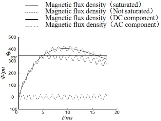
2.1.2. Transient Saturation Characteristics of Electromagnetic Current Transformer
When the magnetic flux density is greater than the iron core saturation flux den-sity Фsat, the current transformer saturates and cannot be linear transmission, and the waveform distortion of the secondary current occurs. When saturation is drawing near, the proportion of the power frequency periodic component to the total magnetic flux density is very small, equivalent to adding a superim-posed the power frequency periodic magnetic flux density with little amplitude value to the linearly-increasing magnetic flux density, as shown in Figure 1.
2.2. Analysis of Electronic Current Transformer Transmission
Characteristics
[image:3.595.236.513.509.717.2]Electronic current transformer has the characteristics of high precision, high
reliability, wide band, non-magnetic saturation problem, anti-interference abili-ty and so on [3] [4] [5]. It first converts the measured current signal into voltage signal by using the air-core coil sensing unit, and then converts the voltage sig-nal into optical pulse sigsig-nal through amplifier, Integrator, A/D conversion, digi-tal signal processing and photoelectric conversion, then transmits optical pulse signal to data processing system on the low voltage side through optical fiber, and finally outputs the digital signal. Electronic current transformer equivalent circuit is shown in Figure 2. Of which, Rs is the total resistance of the coil winding and lead; L is the coil inductance; C0 is equivalent stray capacitance of the coil; Ra is the load resistance.
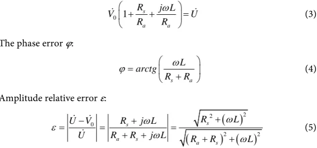
In the steady-state case, ignoring the stray capacitance C0, the phase relation-ship of voltage u(t) and u0(t) is as follows:
0 1 s
a a
R j L
V U R R ω + + =
(3)
The phase error φ:
s a
L arctg
R R
ω
ϕ=
+
(4)
Amplitude relative error ε:
( )
(
) ( )
2 2 0 2 2 s s a s a s R LU V R j L
R R j L
U R R L
ω ω ε ω ω + − + = = = + + + +
(5)
It can be seen from the above two formulas, electronic current transformer phase error and amplitude relative errors are closely related with the coil’s own parameters. In the actual calculation of the case of power frequency, ωL can be ignored, the phase error is almost zero, and the amplitude relative error is con-stant.
2.3. Impact on Protection under Multi Types Current
Transformer Hybrid Operation
As the transmission characteristic of different current transformers is diverse, the use of different current transformers at different intervals may lead to pro-tection device malfunction. 1) if all branches of the bus are using TPY-level cur-rent transformer, the transmission characteristics are basically the same, so pro-
[image:4.595.218.539.259.409.2]tection device can accurately act when the fault occurs internally and externally. 2) if a branch of the bus is using P-level current transformer, the other branches are using TPY-level current transformer, the protection device can accurately act internally but not externally. for example when two consecutive faults occur ex-ternally, P-level current transformer may be seriously saturated, the existing dif-ferential protection device based on 5 ms saturation logic criteria may not de-termine Correctly and block the differential protection, therefore differential protection has the risk of malfunction. 3) if a branch of the bus is using the elec-tronic current transformer, the other branches are using TPY-level current trans- former, protection device can act accurately when the fault occurs internal and external.
3. Dynamic Model Test System of Multi-Type Current
Transformer Hybrid Operation
3.1. Test Scheme of Multi-Type Current Transformer Hybrid
Operation
To study the influence of using multi-type current transformers on the bus-bar protection, the multi-type current transformers includes the P-level current transformer model, the TPY-level current transformer model and the electronic current transformer model. Of which, P-level current transformer’s accuracy grade value of is 5P, limit coefficient is 20, static saturation multiple is 5, primary current error under less than 20 times of its rated current is less than 5 percen-tage. TPY-level current transformer’s rated symmetrical short-circuit current factor is 20, with small air gap iron core, maximum instantaneous error under rated secondary symmetrical short-circuit current is less than peak 7.5 percen-tage, working cycle is 100 ms-500 ms-100 ms, and TPY-level current transfor-mer can simulate field current transfortransfor-mer with current ratio 630/5, 1250/1, 2000/1, 3000/1. The electronic current transformer is 5TPE-level, with sampling amplitude error less than 1 percentage and sampling angle error less than 60 min at the rated primary current, and compound error 5 percentage under the rated accuracy limits primary current.
bus is using electronic current transformer and other branches are using TPY- level current transformer.
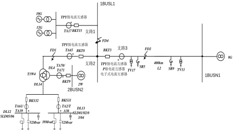
3.2. Dynamic Model Testing System
As a mature and important technical means in the field of power system re-search, the physical dynamic model test has the characteristics of strong empiri-cal, mature technology, accuracy and reliable simulation results [6] [7]. Dynamic test system is shown in Figure 3. M station and N station system are connected by the 500 kV transmission lines, M station installs two generating units (10 G, 12 G) with total capacity 2100 MW. M station is also connected to three-winding transformer, whose medium voltage side is connected to an area equivalent sys-tem and low-voltage side is connected to two 10 kV bus branches; N station adopts half-switch wiring, and is connected to an area equivalent system. Length of the transmission line is 400 km, whose positive sequence parameters are x1 = 0.28 Ω/km, C1 = 0.0135 μF/km, φ1= 86˚, zero sequence parameters are x0= 0.85 Ω/km, c0 = 0.0093 μF/km, φ0 = 76˚, and both ends of the transmission line is equipped with shunt reactor with capacity 150 MVar.
4. Test Results Analysis
Based on the dynamic test system, this paper illustrates the effect of the mul-ti-type current transformer hybrid operation on differential current, braking current and action trajectory of differential protection, taking bus differential protection as an example. Bus differential protection uses braking characteristics of two fold line ratio, the action equation is as follows:
FD2 L2 * SR5 FD4 BKT3 BKT8
TPY级电流互感器
P级电流互感器
电子式电流互感器 *
12G
BKT15
TV17 SR9 TV11
8G 400km * BKS32 * T1W4 52Mvar BKS31 * 39Mvar 52Mvar BKT9 * 2W FD1 TA17 TA65 TA70/ TA71 DL4 DL14 TA61/ TA39 TA2/T A36 10G
支路1
1BUSL1 2BUSN2 DL12 SLD05/06 DL13 SLD01/02/0 3/04
支路2
支路3
1BUSN1
TPY级电流互感器
[image:6.595.58.541.448.715.2]TPY级电流互感器
0.24, 0.3 1
0.6 , 0.3
k k
k k
Ires Iop
Ires Ires
<
= ≥
(6)
Of which, differential current Iop1k = I1+I2+I3 ; braking current
1 2 3
1k
Ires = I + I + I ; I1, I2, I3 is secondary current of current transformer
from each branch. We define the primary current flowing from bus to the out-flow as the positive direction. Currently, the logic to identify current transformer saturation of the bus differential protection mostly using the time difference method, of the way to identify the current transformer saturation is based on severity of saturation, in accordance with the regulations, when the saturation time is 5 ms or more during an external fault, the logic criterion of the existing difference protection can judge correctly and block the differential protection, when the saturation time is less than 5 ms in an external fault, the differential protection has the risk of malfunction.
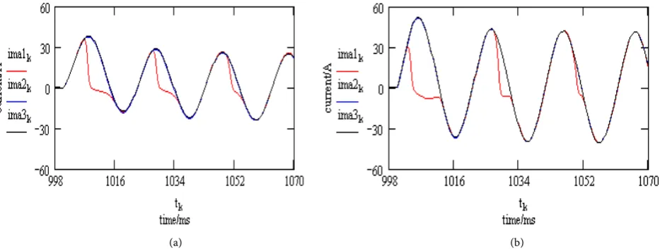
4.1. Comparison Test of Multi-Type Current Transformer
Transmission Performance
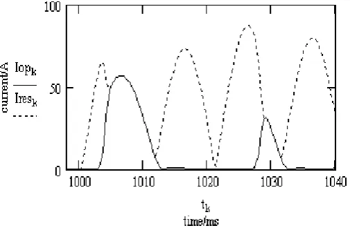
As shown in Figure 3: Branch 1 configures TA1, branch 2 configures TA2, and branch 3 configures TA3. Two consecutive metal faults occur in the FD2, the fault time of which is 100 ms, the actual waveform is shown in Figure 4. ima1k, ima2k, ima3k represent secondary current actual waveform of P-level current transformer, TPY-level current transformer and electronic current transformer, respectively. When the current transformer is seriously saturated, waveform of the differential current and braking current is shown in Figure 5. Figure 4 shows that the difference of three current transformers transmission perfor-mance is not large when the P-level current transformer is not saturated; Figure 5 shows that the saturation time is less than 5 ms when P-class current trans-former is seriously saturated in an external fault, and the time of protection malfunction is within 10 ms.
[image:7.595.65.532.523.699.2](a) (b)
Figure 5. Waveform of differential current and braking current for current transformer serious saturation.
4.2. Test Results Analysis of Multi-Type Current Transformers
Hybrid Operation
Branch 3 of bus is using P-level current transformer, other branches are using TPY-level current transformers. When the metal faults occur in the FD4, the track and action state are shown in Figure 6.
When the internal fault occurs in the TPY-level current transformer and elec-tronic current transformer hybrid operation, protection device can act accurate-ly. When P-level current transformer and TPY-level current transformer are mixedly used for bus, and if P-level current transformer is seriously saturated, protection device can still act accurately in an internal fault, although the diffe-rential current and the braking current appear at the same time and the differen-tial current is large, which is shown in Figure 6.
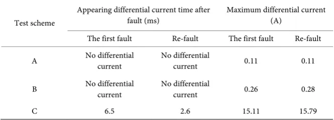
The analysis of differential current after two consecutive external faults is shown in Table 1. Of which, “no differential current” means that the differential current is too small and there is no saturation time.
[image:8.595.249.502.76.241.2]Figure 6. Internal fault track and action state for the line diffe-rential protection (Branch 3 with the P-level current transformer, and other branches with TPY-level current transformer).
(a)
(b)
[image:9.595.262.488.295.665.2]Table 1. Simulation results.
Test scheme
Appearing differential current time after
fault (ms) Maximum differential current (A) The first fault Re-fault The first fault Re-fault
A No differential current No differential current 0.11 0.11
B No differential current No differential current 0.26 0.28
C 6.5 2.6 15.11 15.79
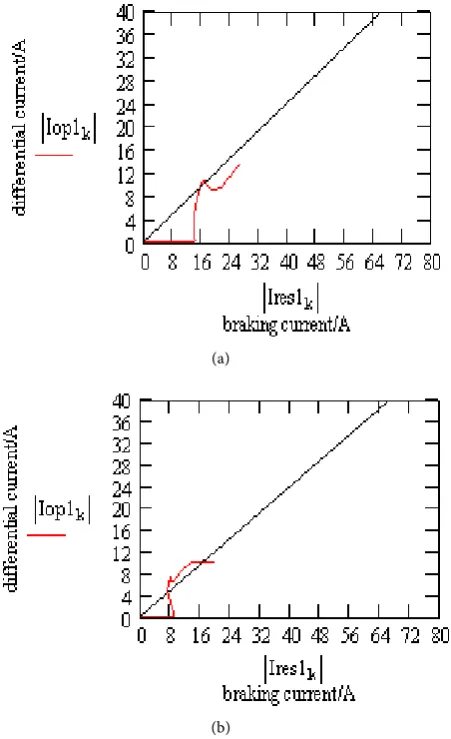
current appearing time is less than 5 ms. The track and action curves are as shown in Figure 7(b).
From the above test results analysis, we can see that when the internal fault occurs, protection device can act accurately based on the transmission characte-ristics of the different types current transformer. While under the C test scheme, when the first external fault occurs, P-level current transformer enters the satu-rated state after 6.5 ms, greater than the normal transmission time of the current transformer 5 ms, so the existing differential protection device based on 5ms sa-turation logic criteria may correctly determine and block the differential protec-tion and differential protecprotec-tion malfuncprotec-tion does not happen. When the external fault occurs again, the electromagnetic current transformer quickly enters the saturated state after about 2.5 ms, less than the normal transmission time of the current transformer 5 ms, so the time difference method based on the saturated criterion may fail. As can be seen from Figure 5, the time window for protection against malfunction may be close to 10 ms in the worst case of saturation. At the same time, we can see from Figure 4 that the secondary current non-periodic components of the current transformer will be significantly reduced if the elec-tromagnetic current transformer saturation is more serious. Therefore, in the case of the current transformers hybrid operation, the normal transmission time of P-level current transformers is less than 5 ms and the current transformer sa-turation cannot be determined. If the non-periodic component change is greater than a certain value, protection based on exports fixed delay 10 ms can avoid the serious saturation effect of the current transformer.
5. Conclusion
is not affected. When the TPY-level current transformer and P-level current transformer is used in the bus, when the first external fault occurs, P-level cur-rent transformer appears a slight saturation, the diffecur-rential curcur-rent is large, the time that the differential current appears is more than 5 ms. When the external re-fault occurs, P-level current transformer is seriously saturated, the differential current is larger, the time that the differential current appears is less than 5 ms, and the differential protection has the risk of malfunction.
References
[1] Yuan, J.X., Sheng, H.L. and Wu, J.Y. (2004) Protection of Current Transformer Ap-plication Guide. China Electric Power Press, Beijing.
[2] DL/T866-2004 (2004) Selection and Calculation of Current Transformer and Vol-tage Transformer.
[3] Hou, H., You, D.H., Yin, X.G., Chen, W. and Xu, T.Q. (2006) Influence and Appli-cation of Electronic Current Transducer on Distance Protection. Power System Technology, 30, 349-353.
[4] Ji, H.Q., Zhang, J., Yang, Y.H., Li, Y.S. and Guo, Z.Z. (2006) Comment on Perfor-mance of Differential Protection Taking into Account Electronic Current Trans-ducers. Power System Technology, 30, 61-65.
[5] Luo, S.N., Tian, Z.B. and Zhao, X.C. (2004) Performance Analysis of Air-Core Cur-rent Transformer. Proceedings of the CSEE, 24, 108-113.
[6] Zhou, Z.X., Zhou, C.X., Dong, M.H., Du, D.X. and Zhang, X.L. (2008) Construction of Dynamic Simulation Lab in SGCC Simulation Center and Research of Protective Relay Test. Power System Technology, 32, 50-55.
[7] Zhou, Z.H., Zhou, C.X., Zhang X.L., et al. (2007) Experimental Study on 1000kV AC System Dynamic Simulation and Relay Protection. China Electric Power Research Institute, Beijing.
Submit or recommend next manuscript to SCIRP and we will provide best service for you:
Accepting pre-submission inquiries through Email, Facebook, LinkedIn, Twitter, etc. A wide selection of journals (inclusive of 9 subjects, more than 200 journals)
Providing 24-hour high-quality service User-friendly online submission system Fair and swift peer-review system
Efficient typesetting and proofreading procedure
Display of the result of downloads and visits, as well as the number of cited articles Maximum dissemination of your research work
Submit your manuscript at: http://papersubmission.scirp.org/