Cost benefit analysis of computer aided engineering
implementation in bespoke engineering business.
RAMAKRISHNAN, Karthik.
Available from Sheffield Hallam University Research Archive (SHURA) at:
http://shura.shu.ac.uk/20264/
This document is the author deposited version. You are advised to consult the
publisher's version if you wish to cite from it.
Published version
RAMAKRISHNAN, Karthik. (2012). Cost benefit analysis of computer aided
engineering implementation in bespoke engineering business. Doctoral, Sheffield
Hallam University (United Kingdom)..
Copyright and re-use policy
See http://shura.shu.ac.uk/information.html
Sheffield Hallam University Research Archive
L e a n III i y a i i u it i i u i m u i i u . . . . __ Adsetts Centre, City Campus
Sheffield S1 1WD
1 0 2 1 0 5 8 5 2 1
Sheffield Hallam University Learning and Information Services
Adsetts Centre, City Campus Sheffield S1 fWD
ProQuest Number: 10700909
All rights reserved
INFORMATION TO ALL USERS
The quality of this reproduction is dependent upon the quality of the copy submitted.
In the unlikely event that the author did not send a com plete manuscript and there are missing pages, these will be noted. Also, if material had to be removed,
a note will indicate the deletion.
uest
ProQuest 10700909
Published by ProQuest LLC(2017). Copyright of the Dissertation is held by the Author.
All rights reserved.
This work is protected against unauthorized copying under Title 17, United States C ode Microform Edition © ProQuest LLC.
ProQuest LLC.
789 East Eisenhower Parkway P.O. Box 1346
Cost Benefit Analysis of Computer Aided Engineering Implementation
Bespoke Engineering Business
Karthik Ramakrishnan
A thesis submitted in partial fulfilment of the requirements of
Sheffield Hallam University
for the degree of Master of Philosophy
December 2012
PREFACE
This report presents the research, findings and recommendations resulting from a
Knowledge Transfer Partnership project between Sheffield Hallam University and
Joseph Rhodes Limited of Wakefield.
The idea of this particular study came from a customer presentation given by Joseph
Rhodes Limited, Wakefield in 2006. The company lost its marketing opportunity for an
order worth about £3 million to the competitor by not having a 3D visualisation and/or
animation of its product. This made the company realise how important is advanced
Computer Aided Engineering (CAE) to their future business.
A dedicated period of two years from June 2007 to June 2009 was allocated to fulfill the
company’s requirements with £56K funding from the UK DTI to the main objective
which was to implement CAE techniques such as 3D modeling, finite element analysis,
dynamic simulation, 3D animation and assess the costs and benefits achieved.
This report and the project’s associated research work, provide a wealth of knowledge
to the reader about the CAE implementation in a bespoke engineering business and the
usage of different techniques available in the market with respect to cost related
benefits. Report appendices include the proof of CAE influence such as customer
satisfaction letter, company catalogues, poster presentations and 3D drawings for the
ABSTRACT
Advanced Computer Aided Engineering (CAE) is a field that expands continuously,
concurrently with technology growth. Exceptional benefits are available by
implementing the techniques in the business activities. Design capability is the biggest
asset to any engineering organisation and it is more important to maintain and update
constantly. It is evident that during 1990 to 2010, the pace of technology growth
reached its peak value and contributes to rapidly improving business growth patterns.
Despite many limitations, it is interesting to see a bespoke engineering firm improve in
performance and their benefits coming from the implementation of these advanced CAE
techniques.
The thesis describes a two year partnership project between Sheffield Hallam University
and Joseph Rhodes Limited, Wakefield in which 3Dimensional Computer Aided Design
(CAD) modelling, dynamic simulation, Finite Element Analysis (FEA) and 3D CAD
animation were applied to four company machines i.e. rubber die press, knuckle joint
press, HME Coining press and clay extrusion machine to enhance both pre- and post
order processes. Direct cost savings of £114,000 were achieved due to savings in
designer's time and materials for major components as a consequence of improved
stress analysis.
The project transformed the company’s traditional method of 2D drawing methods to
3D methods with massive improvement in design standards. It also helps the designers
to develop innovative design ideas with greater confidence and reliability. In addition to
direct savings, improvements in tendering and quotation documentation due to 3D CAD
were instrumental in increasing the overall company turnover by 300% from £7 million
in 2007 to £21 million in 2010 with net profit averaged about £3 million. On conclusion
ACKNOWLEDGEMENTS
This will be my best opportunity to record my journey in Knowledge Transfer
Partnership project between Sheffield Hallam University and Joseph Rhodes Limited.
This particular period is the best part of my life, as I have personally noticed my
confidence level increased.
I would like to say a special thanks to Professors Graham Cockerham and Dr. Syed
Hasan for their wise support and exceptional patient during the Knowledge Transfer
Project and in my thesis writing. I have learnt so many things technically and personally
from the day one I met them and still learning. Without them this thesis would not be
fulfilled.
I am extremely grateful to the board of directors at Joseph Rhodes Limited Mr. Ian
Ridgway (Chairman), Mr. Mark Ridgway (Managing Director), Mr. Barry Richardson
(Sales Director) and Mr. Alistair Nichol (Finance Director) for giving me a wonderful
platform like KTP in my career and supporting me throughout my research activities.
I also like to thank my mentor Mr. Peter Anderton (Technical Director, Joseph Rhodes
Limited) for teaching details of mechanical engineering concepts and guiding me with
some practical examples in day to day activities. The lessons learnt from working with
him direct me towards a clear career path.
I also like to thank my grandfather, mom and uncle for supporting me all these days to
complete the thesis. Without their support, I won’t able to cross this stage in my career
and in life.
Finally, I must convey a special thanks to my wife for the patience shown in taking care
CONTENTS
PrefaceAbstract
Acknowledgements
PREFACE... i
ABSTRACT...ii
Contents... iv
CHAPTER 1 - INTRODUCTION... 1
E l Introduction...1
1.2 Research A im ...1
1.3 Research Outline... 1
1.4 Research Value... 3
1.5 Research Activities...4
1.6 Knowledge Transfer Partnership...4
1.7 Thesis Synopsis by Chapter...7
CHAPTER 2 - DESIGN PROCESS...9
2.1 Introduction...9
2.2 Design...9
2.3 Engineering Design...10
2.4 Design Criteria... 11
2.5 Design Process / Cycle...11
2.6 Design Evaluation... 16
2.7 Design Standards... 16
2.8 Conclusion... 18
CHAPTER 3 - FINANCIAL PROCESS (CAE)...19
3.1 Introduction... 19
3.2 Investment Appraisal...19
3.4 Investment Appraisal Methods...20
3.5 Conclusion...27
CHAPTER 4 - COMPUTER AIDED ENGINEERING...28
4.1 Introduction... 28
4.2 Computer Aided Engineering (CAE)...28
4.3 CAE Advantages...29
4.4 CAE Application...30
4.4.3 Computer Aided Animation...36
4.5 Selection of CAE Software... 37
4.6 Conclusion...40
CHAPTER 5 - DESIGN OF RUBBER DIE PRESS... 42
5.1 Introduction... 42
5.2 Background of Rubber Die Press...42
5.3 Principle of Operation... 46
5.4 Types of Rubber Die Press...47
5.5 10,600 Tonne Rubber Die Press...48
5.6 Development of Rubber Die Press...49
5.7 Cost M atters...52
5.8 FEA of Rubber Die Press...56
5.9 MWP Awards... 86
6.0 Conclusion...87
CHAPTER 6 -DESIGN OF KNUCKLE JOINT PRESS AND MINTING PRESS 89 5.9 Introduction...89
6.2 Knuckle Joint Press (or) Horizontal Impact Knuckle Joint Press...91
6.3 Her Majesty Elizabeth Minting (HME) Press... 95
6.4 Business N eed... 98
6.5 Dynamic Simulation (DS)...99
6.7 Benefits Achieved (Time and Cost)...115
6.8 Conclusion...116
CHAPTER 7 - DESIGN OF CENTEX EXTRUDER...118
7.1 Introduction... 118
7.2 Extruder...118
7.3 2D to 3D CAD Modelling... 120
7.4 Development of Centex Extruder...122
7.5 Conclusion...123
CHAPTER 8 - DISCUSSION AND CONCLUSION...124
8.1 Discussion...124
8.2 Conclusion...126
References:...128
Appendix -1...133
Appendix -2...134
Appendix -3...135
List of Figures
Figure 1: KTP Structure... 5
Figure 2: Group Rhodes Structure (Rhodes, 2009)...6
Figure 3: The traditional and familiar ‘inventor’s’ approach to design: (Childs, 1998) 10 Figure 4: Typical design process vs. One-off design process...15
Figure 5: Rate of Return... 20
Figure 6: Internal Rate of R eturn...24
Figure 7: Computer Aided Engineering - Application... 30
Figure 8: Major Functional Elements of CAD System: (Hsu and Sinha, 1991)...32
Figure 9: Rubber Die Press (1965 and 2008) - John Shaw and Joseph Rhodes Limited42 Figure 10: Guerin Process (Technology, 2005)... 44
Figure 11: Verson - Wheelon Process (Technology, 2005)...45
Figure 12: Marform Process (Technology, 2005)...45
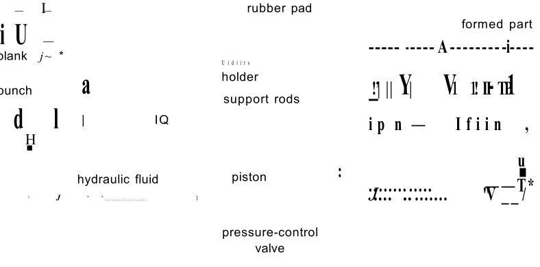
Figure 13: Principle of Operation - Loading... 46
Figure 14: Principle of Operation - Forming... 46
Figure 15: Principle of Operation - Blank holder Effect...47
Figure 16: Principle of Operation - High Pressure Calibraion...47
Figure 17: Testing of 10600 Ton Rubber Die Press...48
Figure 18:On site - 10600 Ton Rubber Die Press...49
Figure 19: Rubber Die Press - 3D CAD... 53
Figure 20: Rubber Die Press - Animation... 54
Figure 21: Cylinder Dimensions... 55
Figure 22: Rubber Die Press- Hydraulic cylinder... 56
Figure 23: Hydraulic cylinder - Geometry and M esh...59
Figure 24: Hydraulic cylinder - Loads and Constraints... 61
Figure 26: Hydraulic cylinder - Max. Principle Stress...62
Figure 27: Hydraulic cylinder - Min. Principle Stress...63
Figure 28: Hydraulic cylinder - Deformation...63
Figure 29: Hydraulic cylinder - Safety Factor...64
Figure 30: Rubber Die Press - Press fram e...65
Figure 31: Frame plate - Geometry and M esh... 66
Figure 32: Frame plate - Equivalent Stress...69
Figure 33: Frame plate - Max. Principle Stress... 70
Figure 34: Frame plate - Min. Principle Stress... 71
Figure 35: Frame plate - Deformation...72
Figure 36: Frame plate - Safety Factor... 73
Figure 37: Rubber Die Press - Pad holder with backing plate... 74
Figure 38: Pad holder - Load schematics... 75
Figure 39: Pad holder - Equivalent Stress -View 1...78
Figure 40: Pad holder - Equivalent Stress -View 2 ...78
Figure 41: Pad holder - Deformation...79
Figure 42: Rubber Die Press - Moving table...79
Figure 43: Moving Table - Load schematics...82
Figure 44: Moving table: Equivalent Stress - View 1...83
Figure 45: Moving table - Load distribution curve across piston circumference...84
Figure 46: Moving table: Equivalent Stress - View 2 ... 84
Figure 47: Moving table - Displacement distribution curve across piston circumference ... 85
Figure 48: Typical Knuckle Joint Press... 89
Figure 49: Time and Displacement Diagram... 90
Figure 51: 3D CAD - Horizontal Knuckle Joint Press... 92
Figure 52: View 1 - Typical Joseph Rhodes Knuckle Joint Press...93
Figure 53: View 2 - Typical Joseph Rhodes Knuckle Joint Press...93
Figure 54: KJ Press - Linkage Assembly...94
Figure 55: Knuckle Joint Press - Link configuration... 94
Figure 56: View 1: HME Minting Press: Joseph Rhodes Limited...96
Figure 57: View 2: HME Minting Press: Joseph Rhodes Limited...96
Figure 58: 3D CAD - HME Minting Press...97
Figure 59: Typical Dynamic Simulation Workflow: Joseph Rhodes Limited... 101
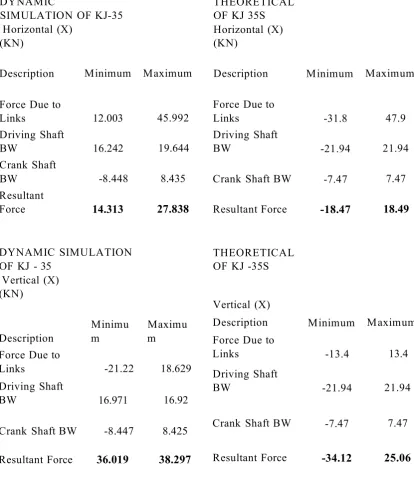
Figure 60: KJ Balancing - Vertical Out of Balance (Theoretical)...103
Figure 61: KJ Balancing - Vertical Out of Balance (Dynamic Simulation)...103
Figure 62: Horizontal Out of Balance (Theoretical)...104
Figure 63: KJ Balancing - Horizontal Out of Balance (Dynamic Simulation)... 104
Figure 64: KJ Balancing - Total Inertial Force (Theoretical)...105
Figure 65: KJ Balancing - Total Inertial Force (Dynamic Simulation)... 105
Figure 66: Linkage Assembly - HME Minting Press...109
Figure 67: Load Faces...I l l Figure 68: Constraints...112
Figure 69: Von-Mises Stress...113
Figure 70: 1 st Principal Stress...113
Figure 71: 3rd Principal Stress...114
Figure 72: Displacement...114
Figure 73: Safety Factor...115
Figure 74: 3D CAD - Craven Fawcett - Centex Extruder...119
Figure 76: Pressure and Velocity profiles during extrusion [Picture Courtesy of
Saravana Kumar Kandasamy]... 123
Figure 77: Velocity and Temperature profiles during steam injection in autoclaves
[Picture Courtesy of Saravana Kumar Kandasamy]...123
List of Tables
Table 1: Joseph Rhodes Design Standards (Roy, 2006)... 17
Table 2: Sample spreadsheet from Expert CAD Management: The complete guide (Green, 2007)...21
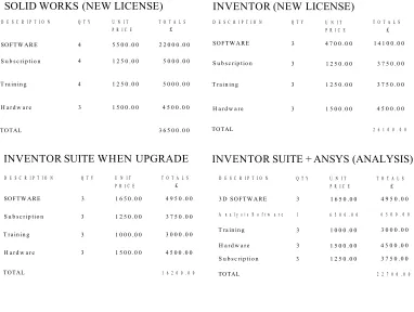
Table 3: Cost comparison between Inventor and Solid works done in 2007 at Joseph Rhodes. (Ramakrishnan, 2007)... 40
Table 4: Cost Saving in terms of Time and Material - Before and After CAE Impl ementation...50
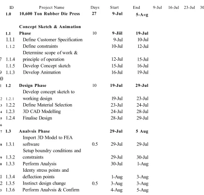
Table 5: Time Plan - CAE activities (Rubber Die Press)...51
Table 6: Hydraulic Cylinder Statistics... 58
Table 7: Hydraulic cylinder - Material Properties: Cast Steel... 59
Table 8: Hydraulic cylinder - Loads and Constraint Definitions...60
Table 9: Hydraulic cylinder - Constraint Reaction...60
Table 10: Hydraulic cylinder - Structural Results...61
Table 11: Frame Plate Statistics... 67
Table 12: Frame plate - Material Properties: EN 50 B... 67
Table 13: Frame plate - Load and Constraint definition... 68
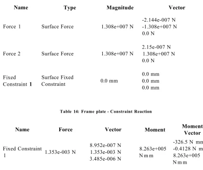
Table 14: Frame plate - Constraint Reaction...68
Table 15: Frame plate - Structural Results... 68
Table 16: Pad holder Statistics...76
Table 17: Pad holder - Material Properties: EN 50B ...76
Table 18: Pad holder - Structural Results... 77
Table 19: Moving table Statistics...81
Table 20: Pad holder - Material Properties: EN 50B ...81
Table 21: Moving Table: Boundary Conditions...83
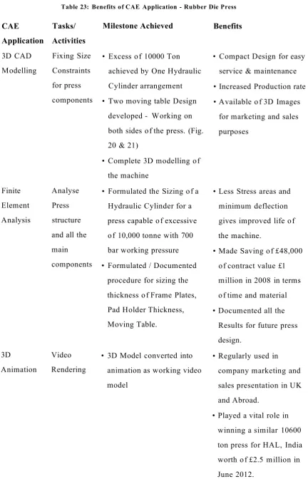
Table 23: Benefits of CAE Application - Rubber Die Press...88
Table 24: Result Comparison...106
Table 25: Material Savings - Designing KJ Press...107
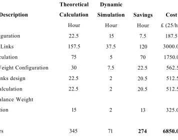
Table 26: Time Plan and Saving - Designing KJ Press... 108
Table 27: Physical Properties...109
Table 28: Analysis Settings... 110
Table 29: Advanced Settings...110
Table 30: Material Properties...110
Table 31: Boundary Conditions...I l l Table 32: Reaction Force and Moment on Constraints... 111
Table 33: Result Summary... 112
Table 34: Benefits of CAE Application - Knuckle Joint Press and HME Minting Press ...117
Table 35: Extruder - Sub-Contract cost Vs Actual C ost... 119
^napter i - mtroauction
CHAPTER 1 - INTRODUCTION
1.1 Introduction
The whole investigation is based on the development work carried out as a part of a
KTP project between Sheffield Hallam University and Joseph Rhodes Limited. The
main goal of the project was to service the growing market of bespoke engineering
design by introducing advanced Computer Aided Engineering (CAE) techniques and to
support new product development with minimum lead-time and cost.
Examples are taken from Joseph Rhodes Limited, to investigate cost effective ways and
uses for implementing CAE techniques in a bespoke engineering business. The works
furnished in this chapter detail the research aim, research objectives, and outlines the
study and the partners involved in the project. In addition, use of advanced techniques
and its needs to the current bespoke engineering business is explained with an example.
1.2 Research Aim
The aim of the research was to evaluate the cost effectiveness of the application of
advanced CAE techniques in a design to order manufacturing business.
1.3 Research Outline
Since the arrival of CAE on the engineering scene in the mid-1980s, there has been
much speculation regarding the benefits to be gained from the use of Computer Aided
Engineering Methods.
Early case study work by Wainright, (1995) clearly identified a minimum of 130% of
design lead time savings in manufacturing industries, achieved by changing traditional
design processes to advanced processes via a case study conducted within a medium
sized and multi-product batch manufacturing company. At the same time 160% savings
were made from moving traditional design processes to modified advanced processes.
^napter 1 - mtroaucuon
This shows the benefits for design by using CAD and its vital role in achieving those
benefits. He also states only product design determines the market uncertainty and
complexity of the product. Therefore, it is evident that by using CAD system, a
considerable amount of design lead time (i.e., cost) can be saved and maximum benefits
can be achieved in manufacturing industries.
Although a survey conducted with 115 companies in 1990's by Short, (2001),
concluded that training and other human factor limitations were preventing most of the
companies in the survey from achieving their target benefits, he implies, companies
from industries such as glass ware, hand tools, roofing construction, masonry grills and
scientific instrumentation have indicated problems stemming from a lack of
management support for use of the system, communication problems and lack of
direction from senior staff. His survey also indicated that the effective utilisation of both
3D and 2D CAD systems were only in large scale industries.
Around the same time, Maylor, (1997) investigated the key factors in successful new
product development (NPD) and the application of tools and techniques in an
organisation. His findings towards new product development and its intensity of use
(IOU) within a firm implied that computer-aided tools only has 52.8% IOU , whereas
project management is known to be most important with 87.2% followed by design for
manufacture with 72%. He concluded that CAD/CAM technology is not in itself
sufficient for a successful NPD strategy; there are many other factors like quality
function deployment, project management and implementation issues which are needed
for successful NPD.
Similar conclusions were drawn by Tantoush, et al., (2001) by a case study approach
from two UK medium sized manufacturing companies with a turnover of £15 to £25
million, suggesting that many of the problems in adopting CAD/CAM are political
within organizations seeking to gain benefit from CAD/CAM systems.
^napier 1 — miroaucuon
Recently, there appears to have been a step-change in the benefits achieved by
companies, as evidenced from an Aberdeen Research Group, (2006) which arose from
companies which migrated from 2D systems to 3D modelling and onto finite element
analysis (FEA). Replacing physical prototypes with virtual prototypes is one of the main
benefits for the people who migrated. For example, manufactures of complex products
that have migrated from 2D to 3D had released their products an average of 41 days
earlier than their competitor with average savings of $15,000, due to fewer prototypes.
This was based upon surveys in the automotive and related industries where mass
production is common and costs for CAD usage can be amortized over large volumes of
product sales. For companies involved in one-off large scale projects, these benefits
may not be available and it would be generally beneficial to a wider audience to be able
to model the economic benefits for these types of company.
Joseph Rhodes Limited is a very good example with orders for single pieces of
equipment well in excess of £1 million and hundreds of man-hours of design time
required. Recent studies by Reid, (2007) have concluded that knowledge management
in these types of companies’ present uniquely different problems to those in mass
production organization, which is likely to be the same for advanced CAE.
1.4 Research Value
This research shows the extent to which Joseph Rhodes selection and implementation
into the business of CAE techniques such as 3D CAD, FEA and 3D animation has
benefited productivity as well as cost effectiveness. The complete research findings
would be helpful to transform a bespoke engineering business from its old traditional
system to modem computer-aided-techniques. These findings are explained through
market analysis and some case study examples from Joseph Rhodes Limited,
Wakefield, UK.
i^napter 1 - introauction
1.5 Research Activities
The work program proceeded as follows:
1. Review company requirements for the application of 3D CAD modelling and FEA.
2. Identify suitable systems to satisfy requirements.
3. Use advanced CAD/FEA to support company design activities and designers across a
number of projects
4. Monitor time and costs incurred when using advanced CAD/FEA and compare with
non-CAD/FEA costs
5. Model costs and benefits from using advanced CAD/FEA in the bespoke
manufacturing environment.
1.6 Knowledge Transfer Partnership
Knowledge Transfer Partnership (KTP) is a government funded programme to
encourage relationships between universities and companies (Figure 1), was established
in 1975 and is renowned as one of the world’s leading knowledge transfer mechanisms.
The main aim of the KTP is to facilitate transfer of knowledge and technology through
university partner and multiply the company skills. As a start the company approaches
local universities and submits their proposals as a structured project. On the success of
the application, the company contribute 40-67 % of the total project cost and the
remainder is contributed by the government. KTP between Sheffield Hallam University
and Joseph Rhodes, Wakefield was formed to introduce a project to implement
advanced CAE techniques and innovative design methods.
unapter i - introduction
ASSOCIATE
C O M P A N Y
KTP
P A R T N E R
P A R T N E R
Figure 1: KTP Structure
1.6.1 Company- Joseph Rhodes Limited
Joseph Rhodes Limited was founded in 1824 and is one of Europe’s largest
manufacturers of metal forming machinery and specialises in bespoke mechanical and
hydraulic pressing machines.
The company is renowned for supplying high quality, state of the art machinery.
Standard models of Mechanical and Hydraulic presses, offered in both Open Front and
Double Sided designs sit alongside highly specialized machinery in the Rhodes
portfolio. From 2003 to 2011, the company has acquired three businesses operating in
different market sectors. These business strands retain some of their former identities
for branding purpose as shown in Figure 2, and are presented to the outside world as
Rhodes Interform - (Aerospace metalworking equipment), Craven Fawcett Limited
(Clay preparation and concrete working equipment) and Beauford Engineers (Structures
for sub-sea oil exploration). The whole businesses are named as Group Rhodes and
operate from an eight acre single site in Wakefield, UK. The company had 180
employees with an average turnover of around £7 million a year in 2007.
cmapier 1 - introduction
HME 0
r hQ d e s
METALFORMING PRECISION CLAYWORKING TECHNICAL MATERIAL RECYCLING AND AEROSPACE MACHINERY ENGINEERING AND CONCRETE FABRICATION HANDLING RENEWABLE AND SPECIAL MACHINERY (OIL AND GAS) SYSTEMS ENERGY PURPOSE
EF
eld
> B EAU FO R D
ENGINEERS H A I L A M S H I R E
)
R H O D ES IBI! RFORM« h Q o « s L iM U l, | j j * " I X ^ tWHITTINGTON
(^rhOdes
C O W LISH A W
WALKER
Dualfbrm S !££
N(fRACTOfflCt I berry!
IslFielding
Figure 2: Group Rhodes Structure (Rhodes, 2009)
1.6.2 Sheffield Hallam University
Sheffield Hallam University is one of the UK’s most progressive and innovative
universities (University, 2010). The university has specialized expertise in e-learning
and offers a variety of distance learning courses. The main vision of the university is to
be renowned as forward thinking, enterprising and business engaged. The university is
situated in the heart of the Sheffield and its suburbs with world class resources and
research facilities.
1.6.3 Partnership Strategy - Example
A significant fraction of company turnover is based on bespoke design of high
performance capital equipment. Even though Joseph Rhodes Limited has a strong
reputation for high quality design, the modem commercial environment demands
concept designs to be produced with some evidence of machine performance to prove
its reliability, stability, and performance. Prior to the KTP programme, the company
design department had predominately completed the designs using manual calculation
[image:22.612.115.495.80.271.2]i^napier 1 - introduction
with 2D drafting. This approach can result in over-conservative designs, which are
uneconomical and have long lead times in the proposal and final design stages. To
change the current situation and to maximize order winning, the company is keen to
explore the implementation of in-house advanced CAE facilities. By implementing
these facilities, the company can keep a strong position among the competitors and
maintain themselves in the current trend.
1.7 Thesis Synopsis by Chapter
CHAPTER 1-Introduction
This chapter explains the Knowledge Transfer Partnership between Sheffield Hallam
University and Joseph Rhodes Limited, which helps to contextualise this research. A
brief account of CAE techniques and typical advantages are included. The main aim of
chapter 1 is to give a clear view of the research outline, aim and the activities
undertaken.
CHAPTER 2- Design
This chapter defines the design process in a typical manufacturing environment. A
typical comparison is also discussed between tradition design process system and
advanced design system following CAE implementation.
CHAPTER 3- Financial Process (CAE)
Finance is one of the important aspect in a business. This chapter provides a small
literature review on investment appraisal methods associated with implementation of
CAE applications inside the business.
CHAPTER 4- Computer Aided Engineering (CAE)
This chapter gives a complete view of the CAE family and its application in a bespoke
engineering business. CAD management and selection of CAD software is briefly
explained for an engineering business dealing in one-off large scale projects.
vnapier 1 — imrouucuon
CHAPTER 5- Design of Rubber Die Press
This chapter describes the background and origins of the rubber die press and its design
process. The chapter focuses on problems developed in manufacturing a one-off large
project and how CAE solid modelling and FEA applications were beneficial to solve
and develop a commercial rubber die press and its components.
CHAPTER 6- Design of Knuckle Joint Press and HME Minting Press
One of the Advanced CAE technique called Dynamic Simulation is explained in detail
with the help of an analysis carried out for a Knuckle Joint Press and Her Majesty
Elizabeth Minting Press. Sample dynamic simulation calculations are included to
illustrate how out of balance forces are balanced, followed by a full process chart
explaining where exactly dynamic simulation fits in the design process.
CHAPTER 7- Design of Centex Extruder
The main theme explained in this chapter is about cost benefits and its implication in
implementing CAE techniques in a bespoke engineering business. One particular group
of machines from Joseph Rhodes was taken into account for the detail study. The study
involves complete 3D modelling with animation and determines the time and cost
required to do it in-house. At the same time the calculated cost and time was compared
to a supplier quotation, to identify the benefits.
CHAPTER 8- Discussion and Conclusion
Details the overall benefits of the CAE implementation and outcome of the Knowledge
Partnership (KTP), project. Also gives an overview of the KTP Awards and winning
partnership (Joseph Rhodes Limited and Sheffield Hallam University) benefits.
vmapier z — uesign
CHAPTER 2 - DESIGN PROCESS
2.1 Introduction
A simple definition of design is an ‘activity which solves problems’ Braha and
Maimon, (1998) concludes in their chapter ‘Design as scientific problem - solving’ as
Design begins with the acknowledgement of needs and dissatisfaction with the current
state of affairs and realization that some action must be taken place in order to solve the
problem. In a bespoke engineering organisation the design activity starts from creating
concept sketches (pre-order stage) to the final manufacturing and assembling of the
product. This particular chapter describes the nature of the company design process and
the associated activities for an engineering business with one-off large scale projects.
Also a typical design cycle for Joseph Rhodes and its associated cost and time are
explained. It is concluded with a detail cost analysis of the current system compared to
the CAE techniques implemented system.
2.2 Design
Design is an essential creative stage in a product development cycle. It generally
originates when a need or requirement for the work arises in the marketplace. Childs,
(1998) indicates the word design originates from the Latin word designare, meaning to
designate or limit. He also states that mechanical design refers to the design of products
and it can be engines, machines tools and precision instruments.
Bronikowski, (1986) defines design as creative ideas which are being converted into a
finished product of some type. Design can be achieved through many stages like
conception, visualization, calculation, analysis, often following standards and
sometimes including optimisation. These stages are the major functional element of the
design activity and without these elements, a good design cannot be generated. Sherwin,
cnapter z - uesign
(1982) and Childs, (1998) suggests it is difficult to break up the design stages as they
are very much inter-linked to each other. However, they also mentioned that businesses
need to find possible solution and evaluations of those solutions are the three basic steps
of the traditional design activity to achieve the solution as shown in the Figure 3. Since
the availability of the computer and its application, design has becomes more
sophisticated for the designer by overcoming the traditional ways of working and saving
time and money. All the key elements are achieved more accurately with less possibility
of human errors. This achievement stands as a big milestone in the engineering
business. As the technology develops, the need for the business to get more focused
obtains, which in turn requires more powerful equipment to solve complex analytical
problems.
Influencing factors
Figure 3: The traditional and familiar ‘inventor’s’ approach to design: (Childs, 1998)
2.3 Engineering Design
Design is the soul of the engineering sector. Parameswaran, (2004) defines design in
engineering as a utilization of available resources which transforms abstract concepts
Cost Benefit Analysis o f CAE Implementation 10
cmapier z — uesign
into discrete details with physical realisation. Eder and Hosnedl, (2007) describes the
Design engineering as solving technical problems, finding suitable and preferably
optimal solutionss for the given task. Also, Engineering design is the field where all the
study, experience and practice are applied together to produce a quality product.
2.4 Design Criteria
A design criterion defines performance and varies from product to product and industry
to industry. As the thesis represents heavy duty machines and their components, the
requirement criteria are very simple and design is an easy process based to a large
extent on technical function. Eide, et al., (2001) states that cost is the only factor which
is heavily weighted when looking after design criterion. However, it also depends on
company needs whether it is going for a brand new design or re-design. Brand new
design always have to go through the design process /cycle before being released. If re
design work is possible, then the design process is a more straight forward and cheaper
task but still it has to be tested to the optimised condition.
2.5 Design Process / Cycle
Armstrong, (2008) describes, the design process is a course of actions used to define
and solve problems. The process starts with the creation of detail product specification
followed by design and implementation. The design process has remained the same over
the past three to four decades but the technology governing the design grows faster at
the same time.
Since this particular project is focused on one-off large scale productions, the process
time is reduced by half with the help of advanced technologies in computers. The
following describes each phase of the company design process.
vmapier z — uesign
2.5.1 Concept Sketch Phase
This is the first step in Joseph Rhodes process and is also called ‘check phase’. In early
stages concept sketches are created by pencil and paper. This is the phase where all the
ideas are generated and the product specification is reviewed for compliance. At least
three to four concept sketches are needed to generate a more critical review and go
through final approval. Computer generated concept sketches can make life easier and
quicker. The generated sketches are then taken to an analysing cycle where the concept
gets confirmed. 3D animation and all other computer graphics can be included to check
the interaction of the products and to understand the system performance. After being
critically analysed the concept sketch is then taken into an experimental phase where the
sketch gets its original shape (product). Concept sketches always add more value to the
design and the product nature.
2.5.2 Preliminary Design Phase
This entails a detailed study of the machine specifications to find the best solution from
possible conceptual alternatives. This is classically described by Bronikowski, (1986) as
a project consisting of designing, drafting, building samples and testing them. All the
sketches from the concept are developed to a defined shape and structure. Then the
shape (product) goes under critical analysis and reviews, where the product turns into its
optimum shape before it passes to final manufacturing. Once the product is defined, it
has to be tested for functionality, safety margins and design constraints.
2.5.3 Detail Design Phase
Immediately after the preliminary design, the detail design phase comes into force. This
phase mainly involves creating manufacturing drawings and detailing the product by
giving appropriate tolerances, using standard symbols, providing various sectional and
vmapter z - uesign
Isometric views. This gives the machinist a greater confidence and less error in
manufacturing the product.. Therefore 2D drawings are used as the best way to provide
a simple and clear view of the product to be manufactured. In Joseph Rhodes, the
draftsman gathers the details from the preliminary design and checks the interference
between the products. After thorough verification, dimensions and tolerances were
made according to the British Standards and finally the drawing is catalogued with a
unique Joseph Rhodes number.
2.5.4 Prototype Phase
This is the most exciting phase where the sketches or models are transformed into
defined physical shape and is an extension of the experimental phase however Raymond
Bronikowski, (1986)states that the prototype test will provide more comprehensive
details about the product than the experimental phase. The prototype phase is where the
product can be tested for its compatibility with other components. Costly mistakes in
design are eradicated by re-designing at this stage. However this practice can be
expensive and may be replaced to some extent by computer software applications, like
CAE modelling and analysis, thus reducing the time and money consuming processes.
2.5.5 Testing
At this point, the product strengths and weaknesses are determined and validated against
appropriate industry standards and also by taking account of appropriates equations for
appropriate material. This will then provide an estimated life and reliability for the
product. If the product fails the testing phase, then it is returned to the preliminary
design phase for modifications. In the past within Joseph Rhodes, calculations were
done theoretically on paper. However, as part of the KTP programme, it has been
largely converted into analysis by the use of based computer programs. This will save
vmapier z — l^esign
the company a considerable amount of time and money in redesign when testing
identifies malfunctions and is particularly important for the company where complete
machines are built in-house and subjected to acceptance trials.
2.5.6 Production and Assembly
This is the final phase of product development, where the product is ready for dispatch.
Previously it is one of the longest phases in the process because of immature machines
and more hands-on processing. These days, advanced machines are capable of
producing faster, more accurate, highly reliable and fully automated processes. This
increases the production efficiency to the greater extent which in turn increases the
profit.
Figure 4 shows the difference between the typical batch design process and one-off
design process. A typical batch design process will have the prototype phase which
eliminates the errors in the design process before going to first line production. Then the
product goes under another checking phase before going to second line production
stage. But for the one-off design process typical of Joseph Rhodes' business, there are
no prototypes or checking phase because of its unique and complex design. Therefore,
in reality if there are any errors in design this will directly affect the production and
assembly phase immensely.
vmapier z - uesign
NO
YES
NO
NO YES
Testing Planning
Testing
Planning Conceptual Phase
Detail Design
Concept Sketches
Detail Design
Production
Assembly First line production
Assembly
Second Line Production Prototype Phase Preliminary Design Phase
MANUFACTURING DRAWING
Preliminary Design Phase
Development of mathematical model
Figure 4: Typical design process vs. One-off design process
vmapier z — uesign
2.6 Design Evaluation
Design evaluation can either take place at the starting stage of the design as formulated
or it can take part at the end of the design cycle as a summative process. Evaluation can
be termed in different ways such as cost based, time based and technical calculation
based. All the three terms are most popular among the design people because it helps to
make decisions. In the case of calculation based, repeat analysis (theoretical or
computational) with different case scenarios helps the designer to decide the best
surroundings (constraint and load case) in the given parameter. Both time and cost
based analyses are given high priority activity because it tends to reflect in the final cost
estimation of the product. A huge difference in this activity, leads the business into a
critical situation. Simon, (1975) points out mistakes in evaluation can be found by
checking and re-checking the habit of the designer.
2.7 Design Standards
Dym and Little, (2004) defines the benefits of design standards as “ standards explicitly
articulate the best current engineering practices in routine or common design
situations” . All the design activities should be carried out within the standards and
within the limitations of the product. Design standards may vary from product to
product and industry to industry. For example Joseph Rhodes Limited, Wakefield
follows four different industry standards such as metal forming and hydraulic presses,
sub-sea structure, clay working and waste management related British Standards to
maintain health and safety and quality of the product. The following Table 1 are some
of the examples of standards used to design machinery at Joseph Rhodes Limited.
vmapiei z, — i^esign
Table 1: Joseph Rhodes Design Standards (Roy, 2006)
1 BS 8888:2002 Technical product documentation (TPD).
Specification for defining, specifying and graphically representing products
2 BS ISO 128-20:1996 Technical drawings. General principles of presentation. Basic conventions for lines 3 BS ISO 128-21:1997 Technical drawings. General principles of
presentation. Preparation of lines by CAD systems 4 BS ISO 128-22:1999 Technical drawings. General principles of
presentation. Basic conventions and applications for leader lines and reference lines
5 BS ISO 128-24:1999 Technical drawings. General principles of presentation. Lines on mechanical engineering drawings Current 20 pgs.
6 BS ISO 406:1987 Technical drawings. Tolerancing of linear and angular dimensions.
7 BS4500/ BS EN20286 ISO Limits and Fits
8 BS EN ISO 4287:2000 Geometrical product specification (GPS). Surface texture. Profile method. Terms, definitions and surface texture parameters Current 40 pgs.
9 BS308 :Parts 1-Withdrawn Engineering Drawing Practice : General Principles 10 BS308 :Parts 2-Withdrawn Engineering Drawing Practice : Dimension and
Tolerance
11 IS09001(1994) Quality Systems - specifications for design, development, production, installation and servicing.
12 BS 5760:Pt 0: 1993 Introductory guide to reliability
13 BS 7373:1998 Guide to the preparation of specifications 14 BS 5760:Pt 6: 1993 Guide to Fault Tree Analysis
15 BS EN 292 Pt 1 and Pt 2 Safety of Machinery Basic concepts , general principles for design
lim p id z, — jufcsign
2.8 Conclusion
Design is the heart of a bespoke engineering business. As discussed in the above
sections, every step in the design cycle starting from concept to manufacture is very
important to the bespoke engineering business because any mismatch in the process and
failure to perform to the standards will results in huge catastrophes. Therefore
maintaining the principles of design and its activity is very important for a bespoke
engineering business in order to achieve the target, being competitive in the market.
cmapier j — rinaiciai rrocess
CHAPTER 3 - FINANCIAL PROCESS (CAE)
3.1 Introduction
Cost targets an control are very important in a bespoke business and the effectiveness of
CAE purely depends on good practise and consumption. Based on the available
information, a thorough investigation is required of the market and a preliminary
estimation such as return on investment, sensitivity analysis and rate of return needs to
be calculated in careful consideration.
3.2 Investment Appraisal
Investment in a project is an initial turning point which gives more power to the project
by providing the necessary financial basis for an effective outcome. In such cases, a few
strategies like rate of return, discounted cash flow payback period can be used for the
detailed analysis in order to place the company in a strong position and to eliminate the
financial risk involved. Also some strategic analyses need to be planned before
commencing and appraising a project. In recent days, plenty of tools have become
available to conduct these kinds of analysis effectively and efficiently. For an
engineering business, the uses of these advanced techniques are required to survive and
to get a strong lead in the current dynamic and competitive market.
3.3 Investment Appraisal Criteria
According to the editors Idowu and Louche, (2011) to appraise an investment project,
the appraiser must have information about the following areas:
1. Cost of Investment
2. Estimated life cycle
3. Estimated cash inflows
vuiapier j — rmaiciai riooess
4. Estimated residual value of the project at the end of its life if applicable
5. Cost of capital
6. Taxation implications of project
7. Inflation rates and effect on project
8. Degree of risk involved
By taking into account the above listed criteria, an appraiser can make an affirmative
decision on the project. McCosker, (1996) also implies before making decision
concerning investment in any projects, an organization needs to consider the above
listed criteria. He further states, in order to assist with investments and minimize the risk
of selecting a project with a low or negative rate of return, it is essential for an
organization to have an awareness of the main financial evaluation techniques used to
evaluate projects.
3.4 Investment Appraisal Methods
3.4.1 Rate of Return (ROR)
As a well known factor in finance, rate of return (ROR), also known as return on
investment (ROI), is the money ratio gained
or lost to the amount of money invested. The
amount of money invested refers to the asset,
capital, principal, or the cost basis of the
investment to the business and often is
proportional to the risk associated with the
project as shown in Figure 5. Also Green,
(2007) indicates most analyst/investors points
out the golden economic rule and the sample spreadsheet presented in Table 2. (Higher
the rate of return is required to be charged for higher risk and vice versa).
Cost Benefit Analysis o f CAE Implementation 20
Rate o f Return
^ iic tp te i j — r iiia iu ia t r i u c c s s t ^ /v c p
Rate of Return = ((Return - Capital) / Capital) x 100%
ROR is usually expressed in terms of percentage towards contribution and is measured
with metrics like profitability. The ROR is directly proportional to the risk involved,
therefore the higher the contribution, the higher the profit. Also according to
Solutionmatrix.com, (2010) most forms of ROR compare investment returns and cost
by constructing a ratio, or percentage. In most ROR methods, if ROR is ratio greater
than 0 then the investment returns more than its costs.
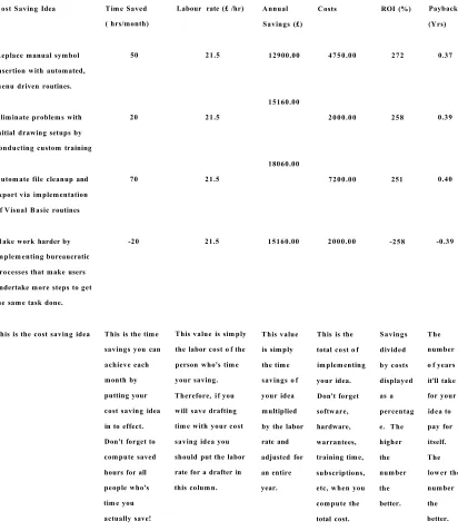
Table 2: Sample spreadsheet from Expert CAD Management: The complete guide (Green, 2007)
Cost Saving Idea Time Saved
( hrs/month)
Labour rate (£ /hr) Annual Savings (£)
Costs ROI (%) Payback
(Yrs)
Replace manual symbol 50 21.5 12900.00 4750.00 272 0.37
insertion with automated, menu driven routines.
Eliminate problems with 20 21.5
15160.00
2000.00 258 0.39
initial drawing setups by conducting custom training
Automate file cleanup and 70 21.5
18060.00
7200.00 251 0.40
export via implementation o f Visual Basic routines
Make work harder by -20 21.5 15160.00 2000.00 -258 -0.39
implementing bureaucratic processes that make users undertake more steps to get the same task done.
This is the cost saving idea This is the time This value is sim ply This value This is the Savings The savings you can the labor cost o f the is simply total cost o f divided number achieve each person who's time the time implementing by costs o f years month by your saving. savings o f your idea. displayed it'll take putting your Therefore, if you your idea Don't forget as a for your cost saving idea will save drafting multiplied software, percentag idea to in to effect. time with your cost by the labor hardware, e. The pay for Don't forget to saving idea you rate and warrantees, higher itself. compute saved should put the labor adjusted for training time, the The hours for all rate for a drafter in an entire subscriptions, number lower the
people who's this column. year. etc, when you the number
tim e you actually save!
compute the total cost.
better. the better.
[image:37.612.91.503.238.715.2]vaiapiei j — rm aiciai riuucss
Drawbacks of ROR
Spiewak and Weiss, (1954) states that ROR does not take into account the cash flow
timing and the calculation is only based on accounting concepts. To add to this, Shim et
al. imply ROR by itself says nothing about the risk of an investment, It simply shows
how returns are compared to cost invested. They further go on to state that ROR does
not indicate future cash flow and it assumes static indicators. Therefore, ROR method
should be utilized along with the other investment appraisal methods, in order to receive
a better outline of the investment.
3.4.2 Discounted Cash Flow (DCF)
Discounted cash flow (DCF) is one of the simplest methods used in investment
appraisal. The DCF shows how quickly (time) the cash flows arising in the project is
equal to the initial investment.
Bolt, (2005) states that DCF is a tool that is used to decide:
1. Which of several possible projects is the most financially appealing.
2. Whether a proposed capital project will be worthwhile.
He also states that the essence of investment is that money is spent now to produce
benefits in the future; assuming those benefits can be quantified in monetary terms, we
need to ask what their present value worth is. In order to calculate this, the net cash flow
that the project will generate over each year of its life and convert this to a present day
value. This will then add up to get the Net Present Value (NPV). Twiss, (1926) says
“Money has a time dimension and it cannot be ignored”. In addition, he added, DCF
provides a valid basis of comparing projects with similar time frames.
By looking at different views, DCF is a tool which only depends on time (Interest and
Discount rates) and it is the only analysis that can predict accurately future cash flows.
It is also the only model that it can be separately used in evaluating project and is more
flexible in adapting two to three different projects simultaneously.
On the other hand Wright, (1973) pointed out, DCF cannot be used as a sole criterion
where projects with wide different time frames are compared.
3.4.3 Net Present Value (NPV)
Net Present Value (NPV) is the method which mainly deals with the duration of the
project, as in this method, the value of t money changes with respect to time i.e., what is
the money value worth today in comparison to the money value worth this time next
year
DeFusco, et al., (2007) outline the following simple rules to calculate NPV of a project
1. Identify all the cash flow associated with the investment (both inflows and
outflows).
2. Determine appropriate discount rate.
3. Using the discount rate, find the present value of each cash flow.
4. Sum up all the present values as NPV
5. Apply NPV rule: if the NPV is positive, an investor should undertake it and vice
versa.
Biz/ed provides the following NPV formula:
Future Value p y =
---( l + i ) n
Where i = interest rate
n = number of years
• The PV of £1 @ 10% in 1 years time is 0.9090
v^napier j — ruiciicicii riucess
• If you invested 0.9090p today and the interest rate was 10% you would have £1
in a year’s time
• Process referred to as: ‘Discounting Cash Flow’
According to Baker and Powell, (2005) NPV is the only method that provides an
objective criterion for making decisions that maximize shareholders wealth. NPV
approach provides theoretically correct “accept-reject” decisions for both independent
and mutually exclusive projects based on their effect on shareholders wealth.
Drawbacks of NPV
From the research work, NPV method mostly depends on the discount rates and these
rates and may vary according to the market fluctuation. Therefore due to its sensitivity
this method is not as useful for comparing to other methods.
3.4.4 Internal Rate of Return (IRR)
Internal rate of return (IRR) is an
investment measure that closely works
with NPV. McAllister and Editors, (2009)
explains when the future cash flows of an
investment are discounted using the IRR,
their present value will be exactly equal to
the initial investment amount.
IRR analysis begins with cash flow stream and use some predetermined social discount
rates to discount future benefits and costs.
Internal Rate of return
D iscounted Rate
Figure 6: Internal Rate of Return
I
=(1
+ /)'
Where / is the rate of discount which solves the equation
sim pler j — rm aiciai riuccss
In order to decide whether or not to include IRR in a business case summary, the
following points should be considered
1. At any time the IRR should be higher, which in turn reduces risk
2. Investment value assessment (increasing or decreasing)
3. Timing of cash flow
4. Tiny investment or expenditure may lead to a magnificent IRR
5. Large cash outflow, (sometimes it can be misled, if there is no large cash
outflow)
Drawbacks of IRR
According to Dasgupta and Pearce, (1972) the only drawback of the IRR approach is
that the solution rate cannot be computed quickly. The reason is simply the IRR is the
solution to a polynomial equation. Geddes, (2002) also agrees IRR cannot be calculated
using a simple calculator and present value tables. It requires a scientific calculator or a
computer spread sheet with the capacity to run iterative operation. In addition he states,
IRR takes no account of the size of the project under analysis.
3.4.5 Payback Method
The payback method is the number of years required to recover the cost invested in a
project or how long does it take to get the original investment back. Any project that
falls short of the standard payback period (negative slope) should be rejected. A project
can be accepted when adding the project’s cash in-flow to its cost, until the cumulative
cash flow turns positive. With reference to Idowu and Louche, (2011), the method
stands that the shorter the payback period, the better the investment. He also states that
the method is widely used where products get outdated quickly such as fashion and
computer industries. In many situations this method is used for an initial screening
cuiapiei j — rmmwai riuucss
process because it is easy to use and to understand. One of the biggest advantages is
that, it gives clear indication of project risk and liquidity issues.
Total Investment Cost Payback in years =
---Annual Benefit
Bolt, (2005) and Idowu and Louche, (2011) agree, one of the main important
disadvantages of this method is that it ignores the time value of money. It also ignores
profitability of the project but stresses the importance of liquidity. In common Frank
Bolt, (2005) and Idowu and Louche, (2011) claims, whether this is an advantage or not
will depend on the area of interest to the individual concerned.
3.4.5 Risk and Uncertainty
Knight, (1921) describes an eminent characteristic between "risk" and "uncertainty". In
the view of Knight's, "risk” refers to situations where the decision-maker can assign
mathematical probabilities to the randomness which he is faced with. In comparison,
Knight's "uncertainty" refers to situations when this randomness "cannot" be expressed
in terms of specific mathematical probabilities. In later stages there are many versions
of definition for risk and uncertainty and is one of the most long running debates
between researchers in financial management.
Risk is a common factor in any form of investments in business. In logic if you have
more uncertainty, the risk is higher and vice versa. Twiss, (1926) describes “None of the
evaluation techniques explicitly takes account of uncertainty with its associated risk”.
Uncertainty is particularly often high in engineering projects because of various
deciding elements in the market.
^napiei j — rmmcicu riutcss
3.5 Conclusion
After the detailed study about investment appraisal and its methods from various
authors' perspectives, the conclusion is that investment in any major project in a
business has to undergo a financial evaluation by taking expected cost and benefits,
time, budget, risk and uncertainty. In an engineering business certain procedures and
logical framework should be calculated because Twiss, (1926) says it has more residual
ignorance. Therefore a meticulous financial evaluation has to be carried out before
making investments in a bespoke engineering business to get a comprehensible outline
of the investment.
sim pler h- — v^umpuiei /\iu eu r,iigm ccim g
CH
APTER 4 - COMPUTER AIDED ENGINEERING
4.1 Introduction
The need for rapid development in engineering businesses arises in the modem world.
Updating and utilising the latest technology gives the solution to the business needs.
This technology flavours in the name of computer and its related accessories. Design
and drawing is the heart of any engineering business. To make the heart run fast and
efficient with full brain power computer aided drawing and technology came in to
engineering businesses. This helps to a great extent in better utilising time and
maximising the efficiency of the product. Evolution of computer into engineering
business made so many people's life easier and effortless.
4.2 Computer Aided Engineering (CAE)
CAE is a group of techniques used to develop or engineer a product with the aid of a
computer. In the last century and in the present century, the world has undergone drastic
and exceptional changes in human lifestyle. The reason behind the growth is an amazing
impact of science and technology. People’s lives are enriched with the increased amount
of growth in the quality of living. The information era was bom in the last decade,
where connectivity and computer software products are driving the people and their
economy. The information and knowledge gathered in this period is huge and is widely
spread from agricultural, engineering to space science. The development of CAE
technology has become more popular in this period and is growing day to day with the
outside world.
As the marketplace is changing so rapidly, it has become indispensable for companies to
merge with the new technologies as quickly as possible. To keep themselves ahead of
their competitors, the companies are thirsting to implement the advanced techniques into
sim pler h- — ^um puiei /\iu cu .cngm ecim g
their business. Techniques such as modelling by CAE systems are extensively used
around the world in different kinds of industries although this report is particularly
focused on its uses in a Bespoke Engineering Businesses. According to Meguid, (1987)
“CAE is a combination of techniques in which man and machine are blended into a
problem solving team, intimately coupling the best characteristics of each.” Since the
emergence of CAE in 1960s, the workload of the engineers has been reduced and an
increase in productivity can be observed. A calculation that took a day for an engineer in
those days can currently be solved within hours with the help of state of art techniques in
CAE. However according to Schaefer, (2006) after second generation CAE invention,
due to increased complexity in an engineering design project then lead time and
productivity remains unchanged. He also states that new generation CAE systems are
constantly developing with various key requirements like intelligent, interactive,
automatic interfaces. Since its capabilities increased day to day, many companies are
busily implementing it into their business. A Census by Jusko, (2007) in Industrial Week
journal says 64.3% of companies who employ more than 500 people, implemented CAE
compare to 43.1% of companies who employ less than 100 people. This also indicates
overall 52.4% of companies have finished implementing these advanced techniques and
shows the growth of CAE techniques in this modern world and how crucial it is to
growing companies
4.3 C
AE Advantages
CAE is about applying computer technology to all stages of product development. The
main advantage of the use of CAE is the ability to test, simulate and possibly validate a
product in a 3D context without having to physically build the machine, which in turn
saves material, money and time.
The following points add more value to CAE and its implementation:
^napiei t- — v^umpuici aiucu j^ngmccimg
1. More realistic way of engineering products with minimum risk involved.
2. Highly sophisticated in performing multiple tasks and saves more time.
3. Optimum material usage leads to reduction in cost
4. Eliminates prototype in design to manufacturing phase. Hub Pages.,(2010).
5. Easy linking of Design and Manufacturing systems, this leads to minimum error
in design and accurate finish of product.
6. Faultless data management system provides great support in re-engineering.
7. Animation or Simulation techniques help the end user to understand the product.
4.4 C
AE Application
CAE and its application are most important in today’s field of engineering. In detailed
engineering business, the computer integrated product development cycle starts from the
concept sketch to the final manufacturing definitions. Figure 7, gives details about the
various techniques used to develop a product in a bespoke engineering business.
Computer Software
Computer Aided Analysis (CAA) Computer Aided
Design (CAD)
Computer Aided Engineering
(CAE)
Computer Aided Simulation (CAS)
Computer Hardware
Computer Integrated Manufacturing (CIM)
Computer Numerical Control (CNC) Computer Aided
Manufacturing (CAM)
Figure 7: Computer Aided Engineering - Application
v^llapici *+ — ^uinpuici rtiucu jj/iigmcci nig
4.4.1 Computer
Aided Design
Evolution of Computer Aided Design (CAD) was a phenomenal milestone achieved in
the engineering sectors to perform geometric modelling. CAD originated when it became
possible to turn paper drawings into computer files. After first step in CAD’s invention
in 1960’s, it made life easier in terms of drawing and became more practical in usage for
the designers and application engineers. Since its start, it is one of the evergreen
techniques which are on the rise to make even more sophisticated and economical
method used by engineering industries. Bone, (1994) and Alavala, (2008) explains, CAD
uses computer to display graphic images on a mathematical co-ordinate system.
Hsu and Sinha, (1991) explains all the major functional elements of computer-aided-
design (CAD) and its development as shown in Figure 8. He also states that CAD can
enhance the quality of engineering design with excellence representation product
geometries. It also enables clear visualiz