Abstract -- The power generation industry has recently
started to invest interest and focus on the single-phase operation of traditional three-phase, wound-field, synchronous generators. This is partially due to a combination of customer requirements and the need to understand the extent of flexibility in their current products. This paper deals with an in-detail analysis of a salient-pole, wound-field, three-phase synchronous generator operating in single-phase condition, at unity power factor. The particular 400kVA alternator is first analysed via the classical analytical equations and the results compared with finite-element and available experimental measurements for validation purposes. The tools developed in this stage are then used to analyse the generator under study when it operates in single-phase condition with different values of load. In this work, it can be observed how single-phase operation of synchronous generators can result in an increase of the power-per-phase performance and that, with the appropriate winding configuration, the machine can be used in single-phase operation with a reduced loading.
Index Terms—Analytical modelling, single-phase operation, salient-poles, synchronous generators
I. INTRODUCTION
HE proven performance capability and its long history in the field of power generation make the wound-field, salient-pole, synchronous generator (SG) the natural choice when an efficient and reliable electrical machine is required for generation applications [1]. In general, such technologies are commonly used for three phase (3θ) applications. There is however an ever-increasing demand for single phase (1θ) systems. While dedicated, 1θ SGs have been around for decades, however commonly-available 1θ SGs are usually only available for comparatively small output and low speed applications [2]. Therefore a lot of interest is today being invested in 1θ generation systems rated for higher power applications. While this would be optimally done by developing new, dedicated 1θ generators from scratch, however a number of SG manufactures have recently begun to investigate the migration of existing 3θ products to 1θ operation. This is due to particular customer requirements, to the ever-changing market demands and to the historic inertia/reluctance of industrial organizations relative to launching new product research programs after having heavily invested in other products. One of the main aims of
C. Spagnolo, S. Nuzzo, C. Gerada and M. Galea are with the Power Electronics, Machine and Control Group, University of Nottingham, Nottingham, UK (email: [email protected]).
G. Serra is with the Department of Electrical, Electronic, and Information Engineering, University of Bologna, Bologna, Italy, ([email protected]).
C. Gerada is with the Power Electronics, Machine and Control Group, University of Nottingham Ningbo, Ningbo, China, ([email protected]).
such efforts is that of investigating the flexibility of such translations in the design and to identify the limits related to these considerations. As will be shown in this paper, 1θ operation of 3θ SGs can result in an increase of the power-per-phase of the machine and that, with minimum disruption to the design mainly based on an appropriate re-wiring, certain machines can achieve an excellent performance in 1θ operation with reduced loading [2].
The analysis carried out in this paper aims at providing a better understanding of the performance of 3θ SGs operating under 1θ loading, as opposed to the more classical 3θ operation of such machines. The main consideration which this paper is based on, is the fact that during such operation, a 1θ alternating current is flowing in the stator winding and a pulsating wave of mmf is thus produced. This field can be separated into two components, namely 1) a component rotating in the same direction as the rotor, referred to as “positive field” and 2) a component that rotates in the opposite direction at relative double the speed, referred to as “negative field”. The second component produces an alternate magnetic flux into the field windings, flowing from the rotor poles and superimposing to the main excitation field. Similarly to the above, this field can be divided into a “positive” and a “negative” component. The latter features the same speed as the main rotor field. The positive field travels at a speed which is three times that of the main rotor field, generating in the stator windings an EMF with a frequency that is three times higher than the main frequency. Therefore, it is clear that the negative sequence of the field needs to be damped by an additional winding which is typically placed in slots distributed along the salient poles of such machines. In fact, the flux density’s negative component induces a voltage at double the supply frequency in the rotor damper bars, producing currents which oppose the asymmetric armature reaction due to the 1θ operation. Considering all the above, then this paper focuses on the analysis of the current flow induced in the damper winding and the associated losses. The paper starts with an in-detail modelling and analysis of a 3θ, salient-pole SG, with special focus on its 1θ operating condition. A preliminary sizing procedure of SGs is described in Section II, using a set of equations to identify the equivalent values of a 3θ machine operating in 1θ conditions. A preliminary set of analytical equations is implemented to estimate the value of excitation current under load variations. In Section III, after a brief description of the machine under study, an in-detail Finite-Element (FE) analysis of the considered 400kVA SG is performed and results compared to the analytical model. In Section IV, one method for evaluating the field current at different loadings is described. In order to validate the proposed methodologies, experimental tests are finally performed on the SG under 1θ loading.
Analysis of salient-pole synchronous generators
operating in single-phase condition
C. Spagnolo, S. Nuzzo, G. Serra, C. Gerada, M. Galea
II. ANALYTICAL CONSIDERATIONS OF THREE-PHASE SGS WORKING IN SINGLE-PHASE CONDITION
The analysis procedure of SGs, designed for ‘normal’ 3θ operation but also aimed at supplying 1θ loads, requires some preliminary considerations, focused on the particular winding configuration. In fact, the 3θ stator winding of such machines has to be connected in such a way that it appropriately works also in 1θ operation. An easy way of obtaining a 1θ SG is to disconnect one phase and series-connect the remaining two phases. In this condition, the 1θ generated power P1 is that
shown in (1), where Vph is the phase voltage, Vll is the
line-to-line voltage and I is the current flowing in the series-connected phases. The output ratio between P1 and the 3θ
power P3 is therefore given by (2) and the ohmic losses in the
stator windings in the case when I1=I3=I are related as
described in (2).
1 31 V I V I
P ph ll
2
578. 0 3 1
3
1
P P
If it was to be assumed that the given dimensions allowed for equal losses in the stator windings for both the 1θ and 3θ cases, the current ratio shown in (3) would be permissible and thus the power ratio is that given in (4).
3
225. 1 2 3
3
1
I I
4
717. 0 2 1
3 3
1
3
1
I ll V
I ll V
P P
Considering the above, then additional analytical considerations can be carry out in order to calculate the value of the excitation current IF needed to feed the different
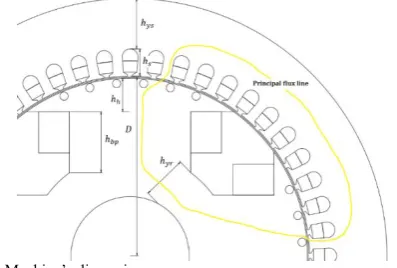
[image:2.595.132.237.250.314.2]loading levels while keeping the output voltage constant. The starting point of this design stage is represented by the B-H characteristic of the lamination sheet. The accuracy of this curve, inherently to its real behavior in the electrical machine under analysis, is of paramount importance for the accuracy of the following calculations. In particular, given the geometrical dimensions of the SG, it is possible to proceed with the evaluation of the magnetomotive (mmf) drops along the principal flux lines.
Fig. 1. Machine’s dimensions.
A general schematic of the machine under analysis is illustrated in Fig. 1. The calculations related to the mmf drops and thus those relevant to the evaluation of the necessary Ampere-turns are given in (5)-(9), where the Ampere’s law is applied along the main flux line shown in Fig. 1. The main aim of this design stage is that of identifying a direct relationship between the total mmfs needed in 3θ and 1θ operations, as described in (2). In order to do this, the first step is to evaluate the Carter’s coefficient kcs [3] for the
magnetic voltage drop in the airgap, calculated with the expression, as described by (5), where µ0 is the permeability
of the free space, BM is the maximum value of the airgap flux
density waveform (which can be assumed in this analysis on the basis of well-known typical values) and δmin is the airgap
length in correspondence of the d-axis.
5
min0
1
BMKcs
By using the same principle, the magnetic voltage drops in the stator tooth, the stator and rotor yokes and the salient-pole can be evaluated. These are described by equations (6)-(9), where HTm, Hysm, Hyrm, Hpe and Hbp are the chosen average
values of the magnetic field inside the respective parts of the considered machine.
6
s Tm TH h
7
ys ysm ysH L
8
yr yrm yrH L
9
bp bp h pe
pH h H h
Having determined all the mmfs drops, it becomes finally possible to calculate the total mmf that has to be provided by one pole in order to compensate for these drops. This is done as shown in (10), while in (11) the value of the field current needed at no-load condition (given the number of turns-per-pole Ntp) is determined.
10
22 yr ys
T tot
11
0 tptot
N F I
The calculations shown above are well-known and very widely used for a first, preliminary sizing of a generic electrical machine operating in normal condition [4-7]. However, for 1θ operations of the SG, some additional considerations have to be taken into account. In particular, using (2) and knowing the value of the current in one phase of the armature winding in 3θ condition, it is possible to determine the current needed to supply the 1θ load, as described in (12).
12
33 1
V P
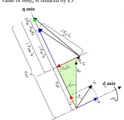
[image:2.595.63.262.597.731.2]This observation can also be seen in the Arnold-Blondel diagram of Fig. 2 where, under the assumption of linear behavior of the ferromagnetic materials, it can be seen that the value of mmfa is reduced by 3 .
Fig. 2. Arnold-Blondel diagram for synchronous generators.
Proceeding with the calculations of the d- and q-axis currents (as shown in (13) and (14)), the value of the no-load emf of the unsaturated machine can be evaluated by (15).
13
)2 ( ) sin( ˆ
I ej
Id a
14
)cos(
ˆ j
e I
Iq a
15
ˆˆ
du d qu q a a a
gu E R I jI X jI X
E
In (15), = , Ra is the armature resistance, Xqu is the
unsaturated q-axis reactance and Xdu is the unsaturated d-axis
reactance. Having determined the above quantities, it is now possible to calculate the value of the mmf that needs to be supported by the rotor when the machine is unsaturated. This is given by using (16), where Egap is obtained from the
no-load characteristic and φn is the rated flux in the airgap.
16
)(
gap E
gu E
n gu
Finally, the ampere-turns necessary when the machine is working in saturated conditions has to be calculated. Prior to this, the internal voltage Ep is determined by using (17) and
finally the total mmf θLtot is evaluated as described in (18). In
these equations, Xσ is the leakage reactance, θFu and θFs are
the values of the unsaturated and saturated rotor Ampere-turns, respectively.
17
ˆˆ ˆ
a a
a a
P E R I jX I
E
18
gu Fu Fs
Ltot
By manipulating (15), the total number of Ampere-turns in 1θ operation can be determined as follows in (19), allowing for returning acceptable values of field current also for 1θ operation.
19
33
1
Ltot Ltot
In order to prove all the above, a detailed FE analysis of a baseline machine, i.e. the above-mentioned 400kVA SG, is carried out. This is discussed in the following section.
III. FEANALYSIS OF THE PLATFORM OPERATING AT MAXIMUM SINGLE-PHASE LOADING A. The considered synchronous generator
The salient-pole, wound-field, SG studied in this paper is a 4-pole alternator, designed for operating at the rated values given in Table I.
TABLE I
MACHINE’S PARAMETERS
S 400kVA Rated apparent power
V 400V Rated voltage
cosφ 0.8 Power factor
f 50Hz Frequency
2p 4 Number of poles
[image:3.595.300.542.297.363.2]The stator winding of the machine has a double-layer structure and is featured with a shortened pitch of 2/3 to remove the triplen harmonics, which are disruptive for the 1θ operation of 3θ SGs. The winding configuration can be observed in Fig. 4, where a cross-section of the machine is shown and the phase A has been highlighted. There are 2 circuits in parallel on the stator winding, each of them is characterized by 8 coils. This is also visible in the cross-section of Fig. 3. Another major feature of the considered alternator is the skewing implemented on the stator stack. This is done with the aim of reducing the slotting effects and thus improving the output waveforms.
Fig. 3. 2-D model of the machine with phase A highlighted
[image:3.595.350.506.511.657.2]B. The FE model
[image:4.595.301.550.96.186.2]Considering the features highlighted in the previous section (especially the one regarding the stator skewing), it is clear that a 3-D modelling would be ideal for the analysis of the 400kVA generator considered in this work. However, in order to reduce the inherent computational resources, a 2-D FE model of the platform is built, with the aim of simulating the machine behavior under 1θ loading. The cross-section of the modelled machine is shown in Fig. 3. Due to the importance of the damper cage during the 1θ operation, particular focus is given to the modeling of this additional rotor winding. In fact, in order to consider potential skin effects into the damper bars ensuing from the stator slot harmonics, each bar is modelled as a solid conductor, as suggested by [8] and [9]. The FE model is coupled to the in-built electrical circuits in the FE software, representing the stator phases, the rotor field winding and the damper cage. All the rotor bars are in parallel and short-circuited by simple circuital connections, while the 1θ operation is achieved by series-connecting the phases A and C of the stator winding, as shown in Fig. 4. Additional circuital components are used to account for the end-winding effects, i.e. the end-winding stator and rotor resistance.
Fig. 4. Electrical circuit of the stator windings for simulating 1θ operation. While at no-load operation, as mentioned in Sections II and III, the value of the excitation current is the same as in 3θ condition, a mmf reduction has to be considered when a generic load is applied. This can be obtained by using and applying (19) to the current source that feeds the circuit coupled to the FE model and relevant to the field winding. Having set-up all the aspects highlighted above in the FE tool, transient with motion simulations are used for the analysis of the machine. In order to take into account the stator skewing, several slices of the generator are analyzed and separately solved [10, 11]. These slices differ from each other for the different initial positions of the rotor with respect to the stator. To be consistent with the skewing feature, the initial position of each slice is a sub-multiple of the skewing angle. All the above is used for validating the preliminary sizing procedure described in Section II. The related comparative exercise is given in detail in the next sections.
C. FE results and comparison at rated single-phase loading (230kW)
Having implemented the FE model described in the previous section, it becomes now possible to compare the related results with the analytical ones. The comparison is carried out at rated, 1θ operation, with the load imposed by using circuital components whose values depend on the investigated operating point. The summary of this
[image:4.595.328.528.236.416.2]comparison is shown in Table II, where an excellent match between analytical and FE results can be observed.
TABLE II
MATCH BETWEEN ANALYTICAL AND FE MODEL Analytical results FE results %
Vrms 400V 413.6V -3.4
Irms 577.4A 596.9A -3.4
P 231kW 247kW -6.9
IF-1θ 33.30A 28.9A 13.2
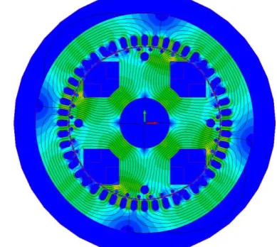
For the sake of completeness, the voltage and current waveforms are shown in Fig. 5, while a field map of the generator under analysis is depicted in Fig. 6.
Fig. 5. Voltage and current waveforms of the 400kVA SG in 1θ operation,
[image:4.595.85.248.331.418.2] [image:4.595.328.523.444.618.2]will not allow for a practical, safe testing of the SG under this studied load condition.
TABLE III
OHMIC LOSSES IN A ROTOR POLE Damper bars numeration Losses [W]
Bar1.1 270
Bar1.2 149
Bar1.3 123
Bar1.4 92
Bar1.5 152
Bar1.6 1051
Considering all the above, the validated FE model is then used for analyzing reduced loading conditions, whose results are provided in the next section and compared with experimental measurements for validation purposes.
D. FE results at 5 kW, 10kW and 15kW
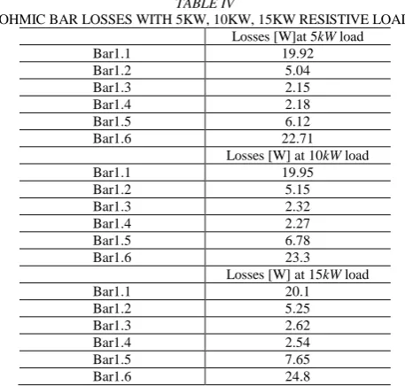
[image:5.595.37.282.96.177.2]Considering the excessive losses shown in the previous section (Table III), then, a preliminary FE analysis is performed in order to predict damper cage losses when the machine operates with lower load. The tests are performed by increasing the resistive load of Fig. 4 in steps of 5kW, 10kW and 15kW. The related results are shown in Tab. IV.
TABLE IV
OHMIC BAR LOSSES WITH 5KW, 10KW, 15KW RESISTIVE LOAD Losses [W]at 5kW load
Bar1.1 19.92
Bar1.2 5.04
Bar1.3 2.15
Bar1.4 2.18
Bar1.5 6.12
Bar1.6 22.71
Losses [W] at 10kW load
Bar1.1 19.95
Bar1.2 5.15
Bar1.3 2.32
Bar1.4 2.27
Bar1.5 6.78
Bar1.6 23.3
Losses [W] at 15kW load
Bar1.1 20.1
Bar1.2 5.25
Bar1.3 2.62
Bar1.4 2.54
Bar1.5 7.65
Bar1.6 24.8
V. EXPERIMENTAL PLATFORM A. Description of the platform
[image:5.595.50.279.335.553.2]In this section, the experimental set-up is described and measurements at reduced load and 1θ operation are carried out. The experimental platform of the particular SG considered in this paper consists of an induction machine drive, acting as the prime mover, whose speed loop controls the frequency of the SG, which is mounted on the same shaft of the motor. The stator winding is connected to a resistive load bank that can be remotely controlled and varied up to 200kW (3θ). The experimental set-up can be observed in Fig. 7.
Fig. 7. Experimental platform of the considered SG. B. Experimental tests
For the reasons explained in the previous section, the resistive load bank is varied from 3.27kW to 18.58kW. The load voltage is controlled by the user (through the DC power supply) in order to be kept at its rated value of 400V. Test measurements can be observed in Table V.
TABLEV
EXPERIMENTAL TEST IN 1θ OPERATIONS
V [V] I [A] P [kW]
398 8.22 3.27
400 16.35 6.54
399 23.28 9.29
399 31.1 12.4
399 38.77 15.47
399 46.56 18.58
FE tests are also carried out to compare the results with those experimentally evaluated and shown in Table V. The comparison between FE and experimental results with equal rated voltage of 400V are shown in Table VI, with an excellent similarity being achieved.
TABLE VI
COMPARISON BETWEEN EXPERIMENTAL AND FE RESULTS
FE Experimental %
3.34 kW 3.27 kW 2
6.67 kW 6.54 kW 2
VI. CONCLUSION
[image:5.595.300.541.399.493.2] [image:5.595.298.543.576.650.2]carried out and then compared with FE results, showing an excellent match. In this particular operating condition, focus was given to the damper cage currents and its associated losses. As expected, due to the necessity to “damp” the negative sequence armature field, the full-load damper winding losses are about ten times the correspondent ohmic losses in 3θ condition. Therefore, intolerable temperature issues on the rotor can be present. Considering this, preliminary FE analyses have been performed in order to identify the limits at which the rotor losses do not cause any irreversible damage to the machine. Hence, experimental measurements have been carried out at reduced loading on the test bench of the SG prototype being investigated in this work. A purely resistive load bank was used to test the machine under 1θ condition, with 2 phases being utilized and one phase disconnected. The test results have been finally performed at constant stator output voltage, showing an excellent match with FE results and proving the validity of the proposed methods. Considering all the above, it is clear that there is still room for improving the design of SGs, when they are designed for optimally operating also in 1θ condition. Future work will focus on re-designing the damper winding of the analyzed generator, aimed at finding an optimal solution in terms of accomplishments at 3θ operation and loss reduction in 1θ condition.
VII.REFERENCES
[1] Renjit, A.A., M.S. Illindala, and D.A. Klapp, Graphical and Analytical Methods for Stalling Analysis of Engine Generator Sets. IEEE Transactions on Industry Applications, 2014. 50(5): p. 2967-2975.
[2] Waters, W.L., Modern development in single-phase generators.
Proceedings of the American Institute of Electrical Engineers, 1908. 27(5): p. 579-586.
[3] Laldin, O., S.D. Sudhoff, and S. Pekarek, Modified Carter's Coefficient. IEEE Transactions on Energy Conversion, 2015. 30(3): p. 1133-1134.
[4] Honsinger, V.B., Sizing Equations for Electrical Machinery.
IEEE Power Engineering Review, 1987. PER-7(3): p. 39-40. [5] Huang, S., et al. A general approach to sizing and power density
equations for comparison of electrical machines. in Industry Applications Conference, 1996. Thirty-First IAS Annual Meeting, IAS '96., Conference Record of the 1996 IEEE. 1996. [6] Bianchi, N., S. Bolognani, and P. Frare, Design criteria for
high-efficiency SPM synchronous motors. IEEE Transactions on Energy Conversion, 2006. 21(2): p. 396-404.
[7] Nuzzo, S., et al. An analytical and genetic-algorithm-based design tool for brushless excitation systems of low-medium rated synchronous generators. in 2016 19th International Conference on Electrical Machines and Systems (ICEMS). 2016.
[8] Nuzzo, S., et al., Improved Damper Cage Design for Salient-Pole Synchronous Generators. IEEE Transactions on Industrial Electronics, 2016. PP(99): p. 1-1.
[9] Nuzzo, S., et al. Damper cage loss reduction and no-load voltage THD improvements in salient-pole synchronous generators. in 8th IET International Conference on Power Electronics, Machines and Drives (PEMD 2016). 2016. [10] Williamson, S., T.J. Flack, and A.F. Volschenk, Representation
of skew in time-stepped two-dimensional finite-element models of electrical machines. IEEE Transactions on Industry Applications, 1995. 31(5): p. 1009-1015.
[11] Gyselinck, J.J.C., L. Vandevelde, and J.A.A. Melkebeek, Multi-slice FE modeling of electrical machines with skewed slots-the skew discretization error. IEEE Transactions on Magnetics, 2001. 37(5): p. 3233-3237.
[12] Bassi, C., D. Giulivo, and A. Tessarolo. Transient finite-element analysis and testing of a salient-pole synchronous generator with different damper winding design solutions. in The XIX International Conference on Electrical Machines - ICEM 2010. 2010.
VIII.BIOGRAPHIES
Cosimo Spagnolo received his B.Sc. degree in Electronic Engineering from
the University of Messina, Messina, Italy, in 2013 and M.Sc. degree in Electrical Engineering from the University of Bologna, Bologna, Italy, in 2016. He is currently a Ph.D. student and Marie-Curie Early Stage Researcher at the Institute for Aerospace Technology Centre at the University of Nottingham and also member of PEMC (Power Machine and Control Group). His current research interests include the analytical approach to design of electrical distribution systems for aircraft.
Stefano Nuzzo received his B.Sc. and M.Sc. degrees in Electrical
Engineering from the University of Pisa, Pisa, Italy, in 2011 and 2014, respectively. He is currently a Ph.D. student with the Power Electronics, Machines and Control Group, The University of Nottingham, Nottingham, U.K. He spent six months with The University of Nottingham as a Visiting Student in 2013, where he was involved in developing analytical and numerical models for the analysis of permanent magnet synchronous machines. His current research interests include the analysis and design of salient-pole synchronous generators and brushless excitation systems.
Giovanni Serra received the M.Sc. degree (with honors) in electrical
engineering from the University of Bologna, Bologna, Italy, in 1975. He joined the Department of Electrical Engineering, University of Bologna, first as a recipient of a Fellowship of the National Research Council, then as a Research Associate, and, since 1987, as an Associate Professor. He is currently Professor of electrical machines in the Department of Electrical Engineering. He has authored more than 180 papers published in technical journals and conference proceedings. His fields of interests are electrical machines, electrical drives, and power electronic converters. His current activities include multiphase drives, direct torque control of ac machines, linear motors, and ac/ac matrix converters. Dr. Serra is Associate Editor of IEEE Transaction on Industrial Electronics and of IEE Electric Power Applications. He is a Member of the IEEE Industry Applications, IEEE Dielectrics and Electrical Insulation, IEEE Industrial Electronics Societies, and of the Italian Electrotechnical and Electronic Association.
Chris Gerada (M’05) received the Ph.D. degree in numerical modeling of
electrical machines from The University of Nottingham, Nottingham, U.K., in 2005. He subsequently worked as a Researcher with The University of Nottingham on high-performance electrical drives and on the design and modeling of electromagnetic actuators for aerospace applications. Since 2006, he has been the Project Manager of the GE Aviation Strategic Partnership. In 2008, he was appointed as a Lecturer in electrical machines; in 2011, as an Associate Professor; and in 2013, as a Professor at The University of Nottingham. His main research interests include the design and modeling of high-performance electric drives and machines. Prof. Gerada serves as an Associate Editor for the IEEE TRANSACTIONS ON INDUSTRY APPLICATIONS and is the Chair of the IEEE IES Electrical Machines Committee.
Michael Galea received his PhD in electrical machines design from the