Performance verification of a 4-axis focus variation
coordinate measuring system
Giovanni Moroni, Wahyudin P. Syam, and Stefano Petr`o
Abstract—Performance verification of a coordinate measur-ing system (CMS) is important for instrument acceptance, re-verification, comparability as well as measurement traceability to the definition of the meter. State-of-the-art ISO 10360 standard series is the reference text about the procedure of verification for CMS. Specifically, ISO 10360-8 considers optical distance sensor based CMSs. This article proposes procedures and artifacts for performance verification of focus variation-based CMS for a simultaneous 4-axis measuring mode. The proposal is inspired by, but goes beyond, the ISO 10360 standard, proposing an original solution for simultaneous linear and rotational axes verification.
Index Terms—Performance Evaluation, ISO 10360 standards, Coordinate Measuring Systems, Focus Variation Microscopy.
I. INTRODUCTION
H
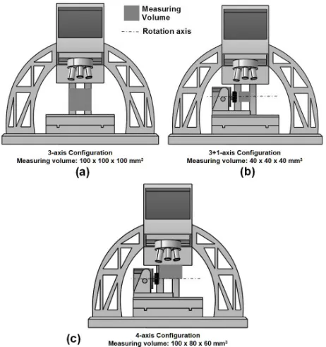
IGH product quality is important to be able to compete in a global market. In order to assure geometrical quality, inspection of a product should be carried out, and the most flexible and accurate type of geometrical verification is coordi-nate measurement. In micro products, a non-contact coordicoordi-nate measuring system (CMS) is preferable to easily access the surface of the part, to eliminate the risk of damaging the surface, and to be able to acquire a large amount of data in a relatively short time (compared to contact CMS). An emerging method for micro-optical CMS is focus variation microscopy (FVM) [1]. This kind of instrument was originally designed for surface texture measurement. Indeed, its ability to scan high aspect ratio surfaces, compared to other microscale measuring instruments, and the long working distance of objective lenses, make FVM capable of 3D geometric measurement. The FVM used in this study to demonstrate the proposed performance verification is a 4thgeneration Alicona InfiniteFocus G4.The FVM considered in this work has a maximum working volume of 100×100×100 mm3 for the basic 3-axis
config-uration without the rotational axis, and a maximum standoff distance (with 5X objective lens) of 23.5 mm. In addition, the 5X lens field of view is equal to about 2.8×2.1 mm2. These characteristics make the FVM an optical CMS for micro geometric measurement. The instrument can be uti-lized in three different configurations: 3-axis, 3+1-axis and 4-axis. The 3-axis configuration only adopts the linear axes
G. Moroni is with the School of Mechanical Engineering, Tongji University, Cao An Road, 201804 Shanghai, P.R. of China
G. Moroni and S. Petr`o are with the Department of Mechanical Engineering, Politecnico di Milano, Milano, Italy
W. P. Syam is with the Manufacturing Metrology Team, Faculty of Engineering, The University of Nottingham, NG7 2RD, Nottingham, UK mail [email protected]
Manuscript received XXX
of the machine. The 3+1-axis configuration adds a rotational axis, and the rotational axis is moved independently of the other axes. Finally, in the 4-axis configuration the linear and rotational axes work together during the measurement. Each configuration requires both different artifacts and procedures for performance verification.
In 3-axis configuration, one can use the maximum mea-suring volume 100×100×100 mm3. The effective measuring
volume of this configuration is illustrated in Fig. 1a. It is possible to add a fourth rotational axis to the configuration, to allow the measurement of part undercuts. However, if one does not consider the ability of the rotational axis to bring the part surface up in front of the optical system, then the effective working volume is reduced to only 40×40×40 mm3in order to avoid collision between the objective nose piece and the rotational axis. Fig. 1b shows the effective measuring volume in this configuration. Finally, it is possible to use the complete 4-axis configuration of the machine, as the four axes working together simultaneously allow a complete measurement of the part by means of a suitably designed measurement strategy [2], [3]. Due to this reason, the conventional measuring volume definition is changed to a new one. The objective lenses will move only in the portion of the measuring volume lying over the rotational axis and the effective measuring volume is equal to 100×80×60 mm3 (only the horizontal configuration of the
rotational axis is taken into account, Fig. 1c). Please note this is not the maximum part size: by activating the rotational axis one can move inside the real working envelope, the portion of the part lying below the rotational axis itself.
Fig. 1. FVM measuring volume definitions (a) 3-axis configuration, (b) 3+1 axis configuration and (c) 4-axis configuration.
symbols can be found in ISO 10360-8 [4]. In this proposal, a focus will be placed on performance verification related to volumetric error (length and probing error). For the 3+1 axis measurement configuration, artifacts and their procedures have been proposed by Moroni et al. [5]. In this type of configuration, there is an additional rotational axis involved. The ISO 10360-8 does not cover the verification of the additional rotational axis, so one must refer to the ISO 10360-3 standard [6] that was originally developed for the verification of the rotational table of tactile CMS [5]. Moreover, for the 3-axis measurement configuration, a proposal of performance verification for this configuration has already been presented [7] and described in-depth [8].
The current separation between part 3 and 8 of ISO 10360 clearly implies the separation between the size measurement and rotational axis error tests. However, in most applications of FVMs with a rotational axis, the four axes work simultane-ously to yield a 4-axis measuring system. In this situation, the measuring volume definition is different compared to the conventional one. Furthermore, the interaction among the four axes can yield a different performance compared to the one obtained in a “3+1” configuration. To go beyond the ISO 10360 standard, a new measuring volume definition will be proposed and an original procedure and artifact for performance verification will be discussed.
The proposed verification procedure and artifact, along with the stated verification uncertainty, can be useful for both the manufacturer and the user to provide a measurement traceability path to the definition of the meter. As such, reliable measurements can be obtained. The proposed artifacts (along with the procedure) link the traceability of an optical CMM to a tactile CMM, which is traced to the definition of the
meter through interferometry-based systems. This article is structured as follows. First, the state of the art regarding verification procedures and artifacts will be briefly reviewed in section II. Shortcomings of the current state-of-the-art procedures will be highlighted. The performance verification for the examined 4-axis FVM CMS will be presented in section III. Finally, in section IV conclusions are drawn, and future recommendation are provided.
II. PERFORMANCE VERIFICATION OF MICROSCALE OPTICALCMSS
In order to verify the performance of any 3D geometric measuring system, both a procedure and a calibrated refer-ence artifact are required. The artifact is very important for the traceability chain of the instrument to the international standard of length (definition of the meter) with a stated uncertainty of the verification procedure. A calibrated artifact should be as simple as possible to facilitate the manufacturing and calibration process and to reduce the overall artifact cost. Moreover, a simple design is important to facilitate the verification procedure [9], making it short enough, including both set-up and execution of the procedure, so that it is com-patible with industrial requirements. Many studies have been conducted regarding procedures and artifacts for performance evaluation of optical distance sensor (non-contact) metrology instruments in macroscale metrology [10], [11], [12].
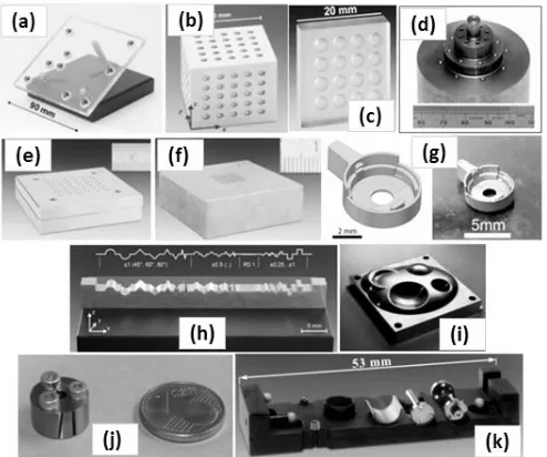
Fig. 2. Existing artifacts to verify the performance of micro optical metrology instruments.
A reference artifact to verify the performance of FVM measuring machines has been proposed by Hiersemenzel et al. [16], [17] and is shown in Fig. 2d. The shape of the artifact is a multi-diameter cylinder. The cylinder is made of stainless steel having spheres on each face. The spheres are arranged along face and body diagonals. The diameter of the spheres is equal to 1 mm. The measurements of the sphere center, in order to calculate spheres distances, were carried out with a 50× objective lens. Ring light and polarizer were used for illumination due to the highly reflective surface. Lateral and vertical resolutions of the measurement are set to 2.93 µm and 0.68 µm respectively. The distances between the sphere centers and the sphere diameters are used to assess the length measurement error of the instrument. One of the measurement results with this artifact is a distance between the spheres of 7.122 mm (standard deviationσ= 1µm). For comparison, the result from CMM measurement is 7.112 mm (σ= 0.06µm). The main goal of their proposal has been to fully implement ISO 10360-8 for an FVM instrument and to provide a way for fast interim checks.
Two micro ball plate artifacts were again proposed by PTB [15]. The first proposal is a micro ball plate consisting of a 6×6 array of stainless steel spheres. The spheres have 1 mm radius. The artifact is shown in Fig. 2e. The nominal distance between the spheres is 4 mm. The second type is a similar artifact except for smaller stainless steel spheres with a radius of 0.25 mm (Fig. 2f). The nominal distance between spheres is 1.3 mm. For both artifacts, the sphere had an Rz ≈1 µm and they were glued on cavities on the plate. For the second artifact, which has smaller spheres, a surface roughening process was applied with an ultrasonic bath utilizing a polishing agent.
Furthermore, proposal of a metalized liquid crystal polymer (LCP) by electroless nickel as reference artifact for micro injection molded part measurement was reported in [18]. The artifacts are used for accuracy assessment of optical
instruments and are also used for calculating the task-specific measurement uncertainty of injection-molded hearing aid com-ponents (Fig. 2g).
Efforts to assess the errors in measuring free-form surfaces have also been proposed. First efforts are accomplished by Savio for tactile CMM measurement [19], [20], by proposing a calibrated artifact for free-form measurement obtained by combination of several basic shape artifacts at a varying location. The artifacts and location configuration shall be chosen to resemble as close as possible the free-form part to inspect. PTB developed [21], [15] an artifact with various type of forms (micro contour reference standard) as shown in Fig. 2h. The contour consists of semi-cylinder segments, sloped areas and steps with different sizes. The main goal is to propose a calibrated artifact for specific form measurement tasks to be measured by an optical instrument. The idea is derived from artifact for tactile stylus instrument acceptance and re-verification. EDM was used to manufacture the artifact with a surface roughness Rz = 1.4 µm, which is well-suited for optical instruments [22]. National Physical Lab-oratory (NPL) [23] proposed a calibrated artifact for free-form surface measurement perfree-formance verification (Fig. 2i). This artifact consists in basic features having both concave and convex spherical shapes. A micro-hole standard artifact made by PTB was proposed for the verification of hybrid tactile-optical instrument (fiber-probe) [15]. The artifact is shown in Fig. 2j. The artifact embodies a calibrated micro-hole of (nominally) 0.125 mm diameter and 2 mm depth. PTB proposed a micro gear wheels artifact as shown in Fig. 2k. The micro gear wheels artifact consist of a micro-planetary gear and three rough balls. The micro-planetary gear can be placed in different orientations. The three rough balls are used to define the artifact reference coordinate system. Measurement results with different orientations can be obtained on this artifact. Back-light illumination can be used as well to measure the artifact due to its cylindrical design. Latest reviews by Claverley and Leach [24] can be referred to for further existing performance verification infrastructure including computed tomography (CT) systems.
From all of the mentioned artifacts and their procedures, none of the proposed verification procedures complies with ISO 10360-8 which implements performance verification along diagonals and linear axis covering at least 66% of the movement length. Moroni et al. [5] proposed artifacts and procedures for performance verification which complies with the standard for 3+1 axis configuration with smaller measuring volume about 60% from its maximum. The artifacts are shown in Fig. 3.
III. PERFORMANCEVERIFICATION OF4-AXISFVM
CONFIGURATION
Fig. 3. Reference artifact to address verification in 3+1 axis configuration. Left: artifact for translational stage. Middle: Artifact for rotational axis. Right: Hybrid artifact for the 3+1 axis configuration.
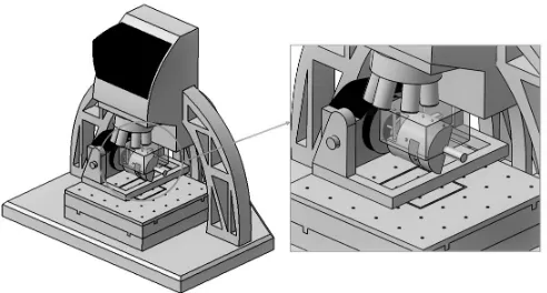
Fig. 4. Measuring volume for the 4-axis configuration, with the new artifact inserted.
TABLE I
MEASUREMENT PARAMETERS FOR THE SPHERE MEASUREMENT
Work piece Exposure time
Contrast Vertical Resolution
Lateral Resolu-tion ISO 3290-1
Sphere
1.45 ms 0.81 0.4 µm 7.82 µm
measure above the rotational axis (Fig. 1c), thus avoiding any objective lens collision and allowing a real 3D measurement of the part to scan. Due to this reason, the measuring volume be-comes 100×80×60 mm3(x, y, z directions), completely above
the rotational axis. The new measuring volume is illustrated in Fig. 4. In this performance verification, the 4 axes of the instrument are supposed to move simultaneously to measure a series of length references. This situation goes beyond the ISO 10360 series of standards, since in this standard the three linear axes and the rotational axis performance are verified separately. This can be compared to the articulating mode test for probing error in the ISO 10360-8. Another axis is being added to the standard 3-axis operation behavior of the system to improve the system flexibility in the case of length measurement.
Regardless of the adopted configuration, the 5× magni-fication lens was used since it has the maximum working distance among available lenses. This reduces the risk of collision between the objective nose piece and the part and gives the maximum field of view (FOV) coverage. Different configurations of steel spheres will be considered as artifacts for performance verification, whose design will be proposed in the next parts of the work. Measurement parameters used to capture the sphere surface are presented in Table I.
A. Proposed artifact
In a 4-axis configuration, the measuring volume, from a “physical” point of view, is still a parallelepiped. A point inside the parallelepiped volume is still defined by the x, y, and z coordinates. However, an additional coordinate, i.e. the rotation angle, is needed to completely define the current configuration of the four axes. The reason is that in order to enable a full 3D measurement each acquisition involves the movement of all the axes.
Therefore, a point location shall be represented as 4-tuple
(x, y, z, θ). The 4-tuple coordinate is divided into two parts. The x, y, z coordinates represent the position along the three linear axes, while the additionalθangle represents the position with respect to the rotational axis. As such, the movement is a 4D movement. The idea is then to consider a four dimensional diagonal, and to map it in a 3D space to design the artifact. There are eight volumetric diagonals in a 4D space, which map on four 3D diagonals. A diagonal in the 4D space can be represented by e.g.
x
y
z
θ
=c
xr
yr
zr
θr
(1)
Where (xr, yr, zr, θr) are the maximum values for the four
coordinates, and c∈[0,1]is a parameter. Let’s map this to a 3D space.
Consider a Cartesian reference systemxyz, so that a corner of the 3D measuring volume is located at the origin, and the whole volume is found in the first octant with respect to reference system point (0,0,0). The position of a rotational axis in this reference system can be defined by its axis of rotation. The axis of rotation itself can be defined by a direction vector a = [a, b, c]T,kak = 1 and a point xa= [x0, y0, z0]
T
. Consider now a reference system (reference system 2) centered in xa, having as third axis the direction
vectora, and rotated counterclockwise by aθangle in respect of reference system 0 around a. This is a reference system integral to the rotational axis. Let’s build the transformation matrix. Consider a Cartesian coordinate system (reference system 1) centered in xa. One of the axes of the system is
vectora. The remaining axes are defined to be perpendicular to this axis, and as similar as possible to the axes of reference system 0. A possible solution for the transformation matrix
0T
1 from system 0 to system 1 is:
i0 = j×a
kj×ak j
0=a×i0
x0=0T1x1=
i0 j0 a xa
0 0 0 1
x1
(2)
where j = [0 1 0]T, and x0,x1 are the homogeneous
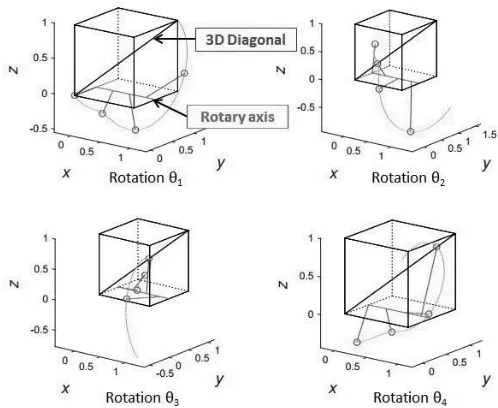
[image:4.612.52.298.182.314.2]Fig. 5. Illustration of 4D to 3D diagonal mapping.
The transformation matrix1T2 from system 1 to system 2
is
x1=1T2x2=
cosθ sinθ 0 0
−sinθ cosθ 0 0 0 0 1 0 0 0 0 1
x2 (3)
where x2 are the homogeneous coordinates of a point in
reference system 2. The total transformation from system 0 to system 2 is
x0=0T11T2x2 (4)
By substituting e.g. the definition of a 3D diagonal x0 =
[cxr cyr czr] T
in (4) and inversion of (4), it is possible to yield the projection in reference system 2 of the 4D diagonal itself. This represents the set of points to which spheres of the artifact must belong so that they are found along a 3D diagonal while a 4D diagonal is developed (Fig. 5). Based on this result, it is possible to develop a reference artifact.
1) Artifact detailed design: The proposed artifact to
eval-uate the performance for the 4-axis FVM configuration will follow the mathematical definition just presented. The main structure of the artifact is an aluminum milled cylinder. Alu-minum was selected because it represents a good compromise between lightness and machinability. To obtain the reference distance between two points, G10 steel spheres are used [25]. Some of the spheres are mounted on cylinders to define their height. There are four sphere configurations on the artifact: 4D diagonal A, 4D diagonal B, x-axis, and y-axis. As in the other proposed artifacts [26], there are four spheres having different distances. Fig. 6 shows the artifact developed for the 4-axis test of the FVM. The design of the artifact depends on the blank which is a solid aluminum cylinder having a diameter equal to 80 mm. The overall size of the artifact is 90×80×80 mm3. Finally, it should be noted that the artifact shape is not as important as the position and configuration of the steel spheres. As such, it is possible to have differently shaped artifacts with identical sphere configurations and positions. Yet, this type of
Fig. 6. The proposed artifact for 4-axis FVM configuration and its corre-sponding volumetric diagonals (4D diagonal A and 4D diagonal B).
artifact applies a significant load on the rotational axis, hence this source of error, too, can be relevant. The weight of the artifact is around 60% of the maximum 3,5 kg allowable mass for the rotational axis as stated by the manufacturer. Fig. 6 also shows the corresponding sphere number and position on the 3D diagonal of the measuring volume box. Finally, it is worth noting that the artifact presents two holders, so that it can be reversed. Fig. 4 shows the artifact mounted on the rotational unit of the instrument along with the measuring volume.
One could think that obtaining independent measurements on a direction with only four spheres is impossible. However, this is not correct. Calibrated lengths are defined on pairs of spheres. In order to make measurements independent, it is sufficient to measure each sphere once for every part of the pair in which it is involved, as suggested by the ISO 10360-8 in clause B.1.
2) Calibration of the artifact: A calibration was carried
out to determine the distances between the pairs of spheres by means of multiple measurements on a CMM. A tactile CMM withE0,MPE= 2+L/300µm (whereLis the measured length
in mm) was used [26]. Thanks to the adopted procedure, which averages several measurement results, the uncertainty can be lower than this E0,MPE.
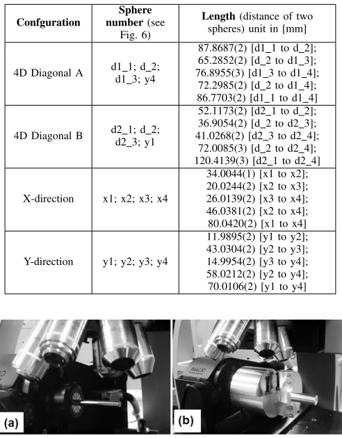
The calibrated sphere center distances are presented in Table II according to the GUM uncertainty notation (for example, the indication 87.8687(2) mm denotes an uncertainty equal to 0.2 µm).
B. Proposed procedure
[image:5.612.321.555.60.187.2]TABLE II
CALIBRATION RESULTS AND THEIR UNCERTAINTIES
Confguration
Sphere number(see
Fig. 6)
Length(distance of two spheres) unit in [mm]
4D Diagonal A d1 1; d 2;d1 3; y4
87.8687(2) [d1 1 to d 2]; 65.2852(2) [d 2 to d1 3]; 76.8955(3) [d1 3 to d1 4];
72.2985(2) [d 2 to d1 4]; 86.7703(2) [d1 1 to d1 4]
4D Diagonal B d2 1; d 2;d2 3; y1
52.1173(2) [d2 1 to d 2]; 36.9054(2) [d 2 to d2 3]; 41.0268(2) [d2 3 to d2 4];
72.0085(3) [d 2 to d2 4]; 120.4139(3) [d2 1 to d2 4]
X-direction x1; x2; x3; x4
34.0044(1) [x1 to x2]; 20.0244(2) [x2 to x3]; 26.0139(2) [x3 to x4]; 46.0381(2) [x2 to x4]; 80.0420(2) [x1 to x4]
Y-direction y1; y2; y3; y4
11.9895(2) [y1 to y2]; 43.0304(2) [y2 to y3]; 14.9954(2) [y3 to y4]; 58.0212(2) [y2 to y4]; 70.0106(2) [y1 to y4]
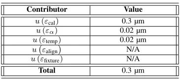
Fig. 7. (a) Measurement of the reference cylinder to determine the rotational axis, and (b) procedure of performance verification.
artifact mounted on the rotational axis. Hence, the verification procedure can be carried out.
The proposed procedure is presented in Fig. 8. For linear axis error verification (x- and y-direction), the procedure is simple: it is sufficient to measure the four aligned spheres (left-to-right-to-left, for x-direction and down-to-up-to-down for the y-direction) without rotating the artifact during axis verification, as shown in Fig. 8c-d.
A different procedure is needed for the diagonal measure-ment. There are two types of diagonal configurations: 4D diagonal A and 4D diagonal B configurations. Table II and Fig. 6 specify the spheres involved in each diagonal. The measurement of these diagonals requires movement of all four axes. To complete the diagonal measurement, four artifact positions are required (see Fig. 6). To obtain all the required positions three rotations are required. Referring to Fig. 6, to measure sphere d 2, a 70° rotation is required from position 1. From this sphere d 2 position (position 2), a 80° rotation is required to measure sphere d1 3 and d2 3. Finally, from position 3, a 100° rotation is carried out to measure sphere y1 and y4. Total rotation required to measure the four diagonal spheres is 250°.
There are two artifact setups to get all 3D volume diagonals mapped. The first setup is the one described as position 1 in Fig. 8a. In this setup position, two volume diagonals (diagonal
Fig. 8. Procedure for the performance verification of the 4-axis FVM configuration.
1 measured on 4D diagonal A and diagonal 2 measured on 4D diagonal B) can be measured. The second setup is carried out by reversing the artifact so that the chuck grips the other artifact holder. In this setup position, diagonal 3 measured on 4D diagonal B and diagonal 4 measured on 4D diagonal A verification can be applied as shown in Fig. 8b. For the diagonal verification procedure, each angular position read by the instrument rotation encoder is recorded. The recorded rotation angle will be used to transform the points in a reference system integral to the artifact.
Sphere fitting is then applied to the points to derive the center of each sphere. Finally, the distances between the centers of pairs of spheres are calculated to verify the length measurement error. The error is calculated as the measured distance minus the calibrated distance.
Please note that, in general, the ISO 10630-8 standard suggests all length measurements to be bidirectional. In the event that bidirectional measurements are hard to perform with the tested measuring system, unidirectional measurement can be adopted instead. In this case, bidirectional measurements must be calculated from unidirectional measurements. Two methodologies are proposed for the calculation. The first one consists in measuring a short material standard of size bi-directionally, and then applying the result to correct the uni-directional measurement. However, in the case of the Alicona InfiniteFocus G4, bidirectional measurements are impossible, even with short artifacts. The second one is based on the inclusion of the probing size error PSize.Sph.1×25;j;ODS and
the probing form error PF orm.Sph.1×25;j;ODS in the length
measurement error. This approach can be followed with an Alicona InfiniteFocus G4.
[image:6.612.52.298.81.396.2]-35 -25 -15 -5 5 15 25 35
0 10 20 30 40 50 60 70 80 90 100 110 120
Error µm
Length mm
[image:7.612.346.529.81.162.2]X-Direction Y-Direction
Fig. 9. Length measurement error for x and y directions.
rotational axes of the instrument. For each configuration, measurements are carried out three times.
C. Results and Discussion
The results for the length errors from the x and y linear axes are shown in Fig. 9. The error behaviors for x- and y-directions are consistent with those calculated in the 3-axis performance verification [5], lying inside a cone of±(5 +L/4)µm (where L is the measured length in mm).
To improve the clearness of the plot, the uncertainty of the test is not shown here. Regarding this uncertainty, it is mainly represented by the artifact calibration uncertainty. Regarding thermal issues, the size of the artifact is quite small, and the tests have been carried out in a temperature-controlled environment with a temperature specification of 20°C±0.5°C . As such, the thermal contribution to the uncertainty proved to be negligible compared to the impact of the calibration uncertainty.
The test uncertainty u(E) can be estimated as follow (ISO/TS 23165 [27]):
u(E) =
s
u2(εcal) +u2(εa) +
+u2(εtemp) +u2(εalign) +u2(εfixture)
(5)
whereu(εcal)is the uncertainty related to calibration;u(εα)
is the uncertainty related to error of coefficient thermal ex-pansion;u(εtemp)is the uncertainty related to the temperature
variation of the measuring environment; and u(εalign) is the
uncertainty related to the part alignment with respect to machine coordinate systems. In this case, u(εalign) = 0since
there is no alignment procedure like those in contact CMSs, e.g. coordinate measuring machines [27], [28].u(εfixture)is the
uncertainty induced by the fixturing, e.g. a deformation of the artifact due to clamping forces. As the artifact is not clamped by the chuck in correspondence of the calibrated spheres, there is no impact of the fixturing on the uncertainty. The uncertainty budget is summarized in Table III.
The uncertainty is calculated for the longest distance be-tween two spheres, which is 120.41 mm. Hence, the maxi-mum expected uncertainty is calculated and presented in this study. For this 120.41 mm length, the calculated uncertainty components are u(εcal) = 0.3 µm, u(εα) = 0.02 µm,
TABLE III
UNCERTAINTY BUDGET FOR THE MAXIMUM LENGTH.
Contributor Value
u(εcal) 0.3 µm
u(εα) 0.02 µm
u(εtemp) 0.02 µm
u εalign
N/A
u(εfixture) N/A
Total 0.3 µm
u(εtemp) = 0.02 µm (so temperature contribution to the
un-certainty is negligible compared to the calibration unun-certainty contribution). Therefore, u(E) = 0.3 µm. It is apparent that this uncertainty is about four orders of magnitude smaller than the length measurement error that will be reported next.
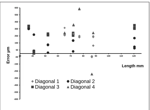
The volume diagonals performance verification results are presented in Fig. 10. This plot shows on the abscissa ten different values of the measured length, and on the ordinate the estimated length measurement error. All results for four diagonals are overlapped on this single graph, with different symbols for different diagonals. As diagonals 1 and 4 are measured 4D Diagonal A, while diagonals 2 and 3 are mea-sured 4D Diagonal B, meamea-sured lengths vary from diagonal to diagonal. As such, for each measured length value 6 (2 diagonals×3 replicas) are present. This plot includes also the calculation of bidirectional measurements from unidirectional measurements. Since the spheres used in the artifact are similar to the spheres used in the artifacts presented in previous works [5], the probing size error and probing form error are similar as well, which arePSize.sph.1×25;j;ODS = 2 µm and
PF orm.sph.1×25;j;ODS= 8µm respectively. The values of both
probing size and probing form errors are negligible compared to the performance obtained for diagonal direction in 4-axis configuration. Turning now to the length measurement errors observed doing the 4-axis test, it can first of all be highlighted that the four diagonals do not show any significantly different behavior: observed length measurement error cover approxi-mately the same range. Second, there is no apparent trend: the length measurement error does not seem to be influenced by the measured length. Finally, observed length measurement errors range from a minimum value 11.4 µm to a maximum value of 630 µm. The average absolute error is equal to 268.1 µm, so it is well-centered between the maximum and minimum errors.
-650 -550 -450 -350 -250 -150 -50 50 150 250 350 450 550 650
30 40 50 60 70 80 90 100 110 120
Error µm
Length mm
[image:8.612.49.301.53.238.2]Diagonal 1 Diagonal 2 Diagonal 3 Diagonal 4
Fig. 10. Length measurement error for the 4 volume diagonals.
to adopt the InfiniteFocus as a full 4-axis measuring system without stitching. The four-axis test instead clearly shows the limits of the system.
Several contributors can be said to cause this reduction in performance. One of the possible contributors for the large error is the weight of the artifact that affects the performance of the rotational axis. The inaccuracy of the rotational axis itself should also be considered. However, probably the most relevant contribution to the lack of accuracy of the 4-axis measurements is the poor effectiveness of the routine for identification of the rotational axis. This procedure is part of the standard operating condition of the machine, and therefore any shortcoming affecting it deteriorates the overall performance of the machine, rather than the uncertainty of the test. The evaluation of this contributor can be based on repeatedly clamping and un-clamping the artifact on the fourth axis. For each clamping, the reference axis of the cylinder is estimated. From all the calculated axes of the reference cylinder, the maximum angle deviation of the axis with respect to the first calculated axis is recorded. The reasoning is that this angle deviation alters when the user changes the reference cylinder, which causes an error in the calculated distance between two spheres, since the axis is used to re-rotate the measured sphere in the original reference system to measure length measurement error. Hence, for maximum length of 120.41 mm, the distance error due to artifact axis deviation from reference cylinder axis has been experimentally estimated to be around 14 µm.
IV. CONCLUSIONS AND FUTURE AIMS
Performance verification of optical CMSs is fundamental. The reason for importance is that it is used for instrument acceptance, re-verification, comparability as well as measure-ment traceability with the stated verification uncertainty. The proposed verification approach for the 4-axis FVM configu-ration is innovative. In fact, it tries to verify the performance of the system when all axes work together simultaneously, rather than considering them separately, while stitching to
the concept of volumetric performance verification. This goes beyond the ISO 10360-8 and ISO 10360-3 standards.
In principle, this approach could be applied to any type of CMS, inclusive of tactile CMMs. This new approach has shown a substantial deviation from the performance verified when considering the three linear axes and the rotational axis separately. This is deemed a shortcoming of the current performance verification procedures. In fact, an Alicona In-finiteFocus G4 has shown reduced performance when a 4-axis test is applied instead of a 3+1-axis test.
Furthermore, this procedure, by simultaneously testing all the axes of the system, can reduce the time required for verifying the performance of the system, which is relevant from an industrial point of view, as it reduces the maintenance downtime of the machine. Also after a non-severe crash, a faster check can be realized to resume regular use.
Future direction includes the search for a simpler single artifact which can be more flexibly applied to any type of measuring system, since, according to the current artifact concept, any different CMS would require a different artifact for performance verification.
ACKNOWLEDGMENT
Financial support to this work has been provided as part of the project REMS - Rete Lombarda di Eccellenza per la Meccanica Strumentale e Laboratorio Esteso, funded by Lom-bardy Region (Italy), CUP: D81J10000220005 and AMALA - Advanced Manufacturing Laboratory, funded by Politecnico di Milano (Italy), CUP: D46D13000540005.
Acknowledgment is due to the Recruitment Program of High-end Foreign Experts of the State Administration of Foreign Experts Affairs.
REFERENCES
[1] R. Danzl, F. Helmli, and S. Scherer, “Focus variation - a robust technology for high resolution optical 3D surface metrology,”Strojniski Vestnik/Journal of Mechanical Engineering, vol. 57, no. 3, pp. 245–256, 2011.
[2] R. Ascione, G. Moroni, S. Petr`o, and D. Romano, “Adaptive inspection in coordinate metrology based on kriging models,”Precis. Eng., vol. 37, no. 1, pp. 44 – 60, 2013.
[3] G. Moroni and S. Petr`o, “Optimal inspection strategy planning for geometric tolerance verification,”Precis. Eng., vol. 38, no. 1, pp. 71–81, Jan. 2014.
[4] International Organization for Standardization,ISO 10360-8: Geomet-rical product specifications (GPS) - Acceptance and reverification tests for coordinate measuring systems (CMS) -Part 8: CMMs with optical distance sensors, International Organization for Standardization Std., Rev. 1, Dec. 2013.
[5] G. Moroni, S. Petr`o, and W. P. Syam, “Four-axis micro measuring systems performance verification,”CIRP Ann. - Manuf. Technol., vol. 63, no. 1, pp. 485–488, 2014.
[6] International Organization for Standardization,ISO 10360-3: Geometri-cal Product Specifications (GPS) – Acceptance and reverification tests for coordinate measuring machines (CMM) – Part 3: CMMs with the axis of a rotary table as the fourth axis, International Organization for Standardization Std., 2000.
[7] G. Moroni, S. Petr`o, and W. P. Syam, “On Performance Verification of 3D Micro Measuring Instrument,” inProceedings of the 28th ASPE Annual Meeting, vol. 56. St. Paul, MN: American Society for Precision Engineering, Oct. 2013, pp. 459–464.
[9] F. Marinello, E. Savio, S. Carmignato, and L. De Chiffre, “Calibration artefact for the microscale with high aspect ratio: The fiber gauge,”CIRP Annals - Manufacturing Technology, vol. 57, no. 1, pp. 497–500, 2008. [10] S. Carmignato, A. Voltan, and E. Savio, “Metrological performance of optical coordinate measuring machines under industrial conditions,”
CIRP Annals - Manufacturing Technology, vol. 59, no. 1, pp. 497–500, 2010.
[11] N. Van Gestel, S. Cuypers, P. Bleys, and J.-P. Kruth, “A performance evaluation test for laser line scanners on CMMs,”Optics and Lasers in Engineering, vol. 47, no. 3-4, pp. 336–342, 2009.
[12] B. Boeckmans, G. Probst, M. Zhang, W. Dewulf, and J.-P. Kruth, “ISO 10360 verification tests applied to CMMs equipped with a laser line scanner,” inDimensional Optical Metrology and Inspection for Practical Applications V, K. G. Harding and S. Zhang, Eds., vol. 9868, Baltimore, Maryland, United States, Apr. 2016, pp. 986 805–986 805–10. [13] M. C. Porath and K. Seitz, “Untersuchungen zum genauigkeitsnachweis
an einem koordinatenmessgert fur mikromechanische bauteile,” VDI-Berichte, vol. 1950, pp. 77–85, 2006.
[14] U. Neuschaefer-Rube, M. Neugebauer, T. Dziomba, H.-U. Danzebrink, L. Koenders, and H. Bosse, “New developments of measurement stan-dards and procedures for micro and nanometrology at the PTB,” in
Proceedings of the 11th IMEKO TC14 Symposium on Laser Metrology for Precision Measurement and Inspection in Industry, LMPMI 2014. Tsukuba: IMEKO-International Measurement Federation Secretariat, 2014, pp. 13–18.
[15] U. Neuschaefer-Rube, M. Neugebauer, W. Ehrig, M. Bartscher, and U. Hilpert, “Tactile and optical microsensors: test procedures and standards,”Meas. Sci. Tech., vol. 19, no. 8, p. 084010, 2008. [16] F. Hiersemenzel, J. Singh, J. Petzing, J. Claverley, R. Leach, and
F. Helmli, “Development of a traceable performance verification route for optical micro-CMMs,” in Proceedings of Laser Metrology and Machine Performance X - 10th International Conference and Exhibition on Laser Metrology, Machine Tool, CMM and Robotic Performance, LAMDAMAP 2013, B. L. Knapp W., Ed. euspen, 2013, pp. 367–374. [17] F. Hiersemenzel, J. Claverley, J. Singh, J. Petzing, F. Helmli, and R. Leach, “ISO compliant reference artefacts for the verification of focus variationation-based optical micro-co-ordinate measuring machines,” in
Proceedings of the 13th International Conference of the European Society for Precision Engineering and Nanotechnology, EUSPEN 2013, S. P. Leach R., Ed., vol. 1. euspen, 2013, pp. 148–151, conference of 13th International Conference of the European Society for Precision Engineering and Nanotechnology, EUSPEN 2013 ; Conference Date: 27 May 2013 Through 31 May 2013; Conference Code:108021. [18] G. Tosello, H. Hansen, and S. Gasparin, “Applications of dimensional
micro metrology to the product and process quality control in man-ufacturing of precision polymer micro components,” CIRP Annals -Manufacturing Technology, vol. 58, no. 1, pp. 467–472, 2009. [19] E. Savio and L. De Chiffre, “An artefact for traceable freeform
mea-surements on coordinate measuring machines,”Precision Engineering, vol. 26, no. 1, pp. 58–68, 2002.
[20] E. Savio, H. Hansen, and L. De Chiffre, “Approaches to the calibration of freeform artefacts on coordinate measuring machines,”CIRP Annals - Manufacturing Technology, vol. 51, no. 1, pp. 433–436, 2002. [21] M. Neugebauer and U. Neuschaefer-Rube, “A new micro artefact
for testing of optical and tactile sensors,” inProceedings of the 5th Euspen International Conference and 7th Annual General Meeting of the European Society for Precision Engineering and Nanotechnology, F. Chevrier, Ed., vol. 1, Montpelier, France, 2005, pp. 201–204. [22] E. Cuesta, D. Gonzalez-Madruga, B. J. Alvarez, and M. Garcia-Dieguez,
“Development of a behaviour curve for quality evaluation with optoelec-tronic profilometers,” inAdvances in Manufacturing Systems, ser. Key Engineering Materials, vol. 615. Trans Tech Publications, 7 2014, pp. 51–56.
[23] B. Acko, M. McCarthy, F. Haertig, and B. Buchmeister, “Standards for testing freeform measurement capability of optical and tactile coordinate measuring machines,”Meas. Sci. Tech., vol. 23, no. 9, p. 094013, 2012. [24] J. Claverley and R. Leach, “A review of the existing performance verification infrastructure for micro-CMMs,” Precision Engineering, vol. 39, pp. 1–15, 2015.
[25] International Organization for Standardization, ISO 3290-1: Rolling bearings – Balls – Part 1: Steel balls, International Organization for Standardization Std., Rev. 2, 2014.
[26] ——,ISO 10360-2: Geometrical product specifications (GPS) – Accep-tance and reverification tests for coordinate measuring machines (CMM) – Part 2: CMMs used for measuring linear dimensions, International Organization for Standardization Std., Rev. 2, Sep. 2009.
[27] ——,ISO/TS 23165: Geometrical product specifications (GPS) – Guide-lines for the evaluation of coordinate measuring machine (CMM) test uncertainty, International Organization for Standardization Std., Rev. 1, 2006.
[28] E. Savio, “Uncertainty in testing the metrological performances of coor-dinate measuring machines,”CIRP Annals - Manufacturing Technology, vol. 55, no. 1, pp. 535–538, 2006.
Giovanni Moroni obtained a cum laude degree (Laurea) in Industrial and Management Engineering at Politecnico di Milano (Italy), where he currently is Full Professor in Manufacturing Technology and Systems (since 2005). He is the head of the Manu-facturing and Production Systems Research Line of the Mechanical Engineering Department at Politec-nico di Milano (since 2008) and member of the Sci-entific Commission of the Department (since 2013); member of the Italian Association for Manufacturing - AITeM (since 1995); Associate Member of CIRP, The International Academy for Production Engineering (since 2012); and founding member of the E-GRT: European Group of Research in Tolerancing (June 2015). Since January 2015, he is China National High-end Foreign Experts at the School of Mechanical Engineering, Tongji University, Shanghai, Peoples Republic of China.
Wahyudin P. Syam was born in Patani-Gebe, Maluku, Indonesia, in 1984. He obtained a Ph.D. degree in mechanical engineering from Politecnico di Milano, Milano, Italy, in 2015. His PhD topic was performance verification and measurement un-certainty analysis of optical coordinate measuring machine under the supervision of Prof. Giovanni Moroni and Prof. Stefano Petr`o.
Since 2015, he is a research fellow in Manufac-turing Metrology Team (MMT) at The University of Nottingham, UK. His current project is develop-ment and manufacturing of precision optical micro-CMM incorporating the Information-Rich Metrology (IRM) principle for the use of form and surface texture measurement. In addition, he is working in lattice design and additive manufacturing for metrology frame. His main research fields are: metrology of geometry (form) and surface texture, precision instrument design and additive manufacturing.
Wahyudin is a member of EUSPEN and is being nominated as CIRP Research Affiliate (UK representative)
Stefano Petr`owas born in Monza, Italy, in 1979. He obtained a Ph.D. degree in Technology and Manufacturing Systems from Politecnico di Milano, Milan, Italy, in 2008. His PhD topic was the planning of measurement strategies with coordinate measur-ing systems.
Since 2008, he is research fellow at Politecnico di Milano. In 2010 he spent a research period at the “Center for Precision Metrology” of the University of North Carolina at Charlotte on performance veri-fication and calibration of micro measuring systems. Since 2011, he is assistant professor at the Department of Mechanical Engineering of Politecnico di Milano. His research topics include all the aspects of the Geometric Product Specification system, from tolerancing to measuring system management and use.