Collision Avoidance Control for Mobile Robot
Based on
Online Analysis of Walking Pattern
Tomoyuki NAKAO
∗and Naoki WADA
∗and Ken’ichi YANO
∗Abstract—In obstacle avoidance control between several types of objects, when interactive avoidance occurs, if the objects avoid each other by moving in the same direction at the same time, they will get into a blocking situation. In this study on the basis of an analysis of a walking pattern and avoidance be-havior, an avoidance control method for interactive avoidance between a robot and pedestrian is devel-oped. Our proposed method can estimate and deter-mine the states of a pedestrian during walking that are the acceleration of a hidden unmeasurable leg, the right or the left and the idling leg or the supporting leg. On the basis of our analysis, the timing for the robot to start to avoid and the direction of avoidance is generated to indicate a safe way for it to avoid to a pedestrian. Through a verification experiment with actual equipment, the applicability of our method will be shown.
Keywords: Mobile Robot, Collision Avoidance Control, Motion Analysis, Human intention, Kalman Filter
1
Introduction
In recent years, future generation intelligent robots that can autonomously execute tasks have actively been developed.Most autonomous moving robots are for use in service businesses, for instance, security robots, guid-ance robots and tray service robots. Autonomous moving robots can move around a workspace with moving mech-anisms, for instance, wheels, crawlers and legs. In an actual workspace with service robots, both humans and robots exist together, and both must move so as to avoid collisions with each other. If a robot cannot execute a cooperative avoidance with a human, a collision will be highly possible. This puts humans in danger and causes a deterioration in work efficiency.
Collision avoidance control of static obstacles and dy-namic obstacles has actively been researched[1][2][3].On collision avoidance of dynamic obstacles, previous meth-ods are effective for an obstacle moving linearly and fol-lowing prepared paths. But in the case of a robot passing
∗Manuscript submitted December 27, 2009. T. Nakao, N. Wada
and K. Yano are with Department Human and Information Systems Engineering, Gifu University, 1-1 Yanagido, Gifu, Gifu 501-1193, JAPAN, Email: [email protected]
an oncoming human, those methods involve the possibil-ity of a collision because they are based on unilateral avoidance by the robot and do not consider actual hu-man’s avoidance behaviors against the robot. Therefore, an avoidance system for cooperating with pedestrians is required.
To make a robot understand the intention of pedestri-ans, a system is required that can estimate the intention of someone’s behavior and communicate it to someone. In a method that uses a camera, there is the problem of insufficient control speed resulting from time delays due to huge quantities of data processing. A system is thus required that can estimate intention with less in-formation. For a collision avoidance control system that uses the methods of Artificial Potential Fields, a robot necessarily changes movement in an adverse direction to-ward pedestrian. However, it is not necessarily the case that a pedestrian will avoid it in a staggered direction toward a robot. If the avoidance direction of a robot and pedestrian is the same, a collision or a blocked passage is unavoidable.
In this study, to make robots and pedestrians able to pass safely without collisions, we propose a collision avoidance control method that creates voluntary avoid-ance behavior by focusing on motion constraint in switch-ing an idlswitch-ing leg or a supportswitch-ing leg.
In this paper, in Section 2, we expound a walking pat-tern model with a criterion for estimating walking states and a method for estimating the velocity of an idling leg. In Section 3, the details of Voluntary Guidance Type Collision Avoidance Control is expounded. On the ba-sis of an analyba-sis of the walking and avoidance behavior of pedestrians, a collision possibility condition, an avoid-ance condition, an avoidavoid-ance starting point and a col-lision avoidance algorithm are expounded. In Section 4, through a verification experiment with actual equipment, the applicability of our method will be shown.
2
Estimation of Walking Pattern
2.1
Acceleration Based Walking Model
with each other as the idling leg lands. To formalize the walking state, a cycle of walking is separated into four Stages with respect to the state of a leg, as show-ing Fig.1[4].The initial state is with both feet on land and with the feet wide apart back and forth. Stage 1 involves swinging the back leg to a place where both legs are together. In Stage 2 the idling leg moves past the supporting leg to a landing. The states after the idling leg switches places with the supporting leg are Stages 3 and 4 and are similar to the first two stages.
In Fig.2 a change of acceleration and the velocity in each stage is shown where the foot motion is simplified to an uniform accelerated motion.In Stage 1 and Stage 3, the velocity of the foot of the idling leg increases at uniform acceleration and in Stage 2 and Stage 4, it de-creases at uniform acceleration. The velocity of the foot of the supporting leg is zero due to landing.
T
Swinging Landing
Right foot Left foot
Stage 1
Stage 4 Stage 3
Stage 2
a stride d
T T
1 2 1
[image:2.595.314.541.79.266.2]2
Figure 1: Partitioned a cycle walking
Let a cycle of walking beT.Let the time, acceleration and velocity be respectively t,a and v.Right and left are presented by indexlandr; a walking model using ac-celeration and velocity is defined byW Mi= [alarvlvr],
where i represents Stages i = 1,2,3,4.On nth cycle walking, W Mi can be represented by Eq.(1)∼Eq.(4) in
every Stage.f is the acceleration function of the leg,v˙l
is the direction vector of velocity, and vst1,n and vst3,n
are, respectively, the velocity at the end of Stage 1 and Stage 3. As using this model with the actual measured parameter, the states of a pedestrian will be estimated.
Stage 1:T n≤t < T n+14T
W M1= [ 0 frv˙r 0 ar(t−T n) ] (1)
Right foot Left foot
v
a
t
t
Stage 1 Stage 2 Stage 3 Stage 4
v
st3v
st1Figure 2: Acceleration based walking model
Stage 2:T n+14T ≤t < T n+12T
W M2=
[
0 −frv˙r 0 ar{t−T(n+
1
4)}+vst1,n
]
(2) Stage 3:T n+12T ≤t < T n+34T
W M3=
[
flv˙l 0 al{t−T(n+
1 2)} 0
]
(3)
Stage 4:T n+34T ≤t < T n+T
W M4=
[
−flv˙l 0 al{t−T(n+
3
4)}+vst3,n 0
]
(4)
2.2
Application of Kalman Filter
Let us consider measuring the feet position with a 2D range sensor to estimate the walking pattern using as little information as possible. Because the range sensor can only measure the shortest distance to the objects, both legs cannot be measured at the same time, i.e., the idling leg motion in Stage 1 and Stage 3 cannot be measured. Changes in the measurement is plotted as a square-wave along the direction of movement from side to side. This method is thus not directly appropriate for use in the above walking model. However, to execute col-lision avoidance control, real-time velocity data for the idling leg are required. Thus, a Kalman Filter is applied to estimate the unmeasurable idling leg motion.
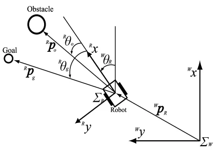
On destination accession control the relationship be-tween a robot and pedestrian on a world coordinate sys-tem∑W is modeled as shown in Fig.3.Setting the direc-tion of the movement of the robot as reference line;Rθ
g
is an argument for the direction to a destination; Rθo is
[image:2.595.56.285.307.510.2]! !
Figure 3: World coordinate system and robot coordinate system
as positive. The position, velocity and acceleration of a pedestrian are, respectively, Wp
o = (Wpox,W poy),
Wv
o = (Wvox,Wvoy) and Wao = (Waox,Waoy).
Be-cause the change of acceleration is discontinuous due to the switching between the idling and supporting legs, a nonlinear Kalman Filter is applied. With the sampling time ∆t, a state equation is represented by the following, whereω is the noise of the state model.
Wx
o(k+ 1) =F·W xo(k) +G·W uo(k) +ω (5)
Wx
o(k) =
[ W
pox(k) Wpoy(k) Wvox(k) Wvoy(k)
]T
(6)
Wu
o(k) =
[W
aox(k) Waoy(k)
]T
(7)
Then, let the state transition matrixes F and G be de-rived.The position and velocity are varied by the accel-eration during the sampling time ∆t, and the following equation is obtained.
F =
1 0 ∆t 0
0 1 0 ∆t
0 0 1 0
0 0 0 1
G=
1 2∆t
2 0
0 12∆t2
∆t 0
0 ∆t
(8) Wu
o(k) is discontinuous and varies by the vector of the
direction of the acceleration. Accelerations of each Stage are presented below.
Stage 1:
Wa
lx(k) = 0 , Wary(k) =Aave Wv˙r(k) (9)
Stage 2:
Wa
lx(k) = 0 , Wary(k) =−Aave Wv˙r(k) (10)
Stage 3:
Wa
lx(k) =Aave Wv˙l(k) , Wary(k) = 0 (11)
Stage 4:
Wa
lx(k) =−AaveWv˙l(k) , Wary(k) = 0 (12)
Aave=
2d T2
i
= (2d
T
2
)2 =
8d
T2 (13)
Ti anddare, respectively, the average idling leg
measur-ing time and average stride. If Ti and d have not
mea-sured yet, the general average values are applied. Wv˙
o(k)
is a unit vector corresponding to the direction of veloc-ity. The observation vectorWy
o(k) is represented by the
state vector Wx
o(k) as follows, where ϵ is the noise of
observation.
Wy
o(k) =H Wxo(k) +ϵ (14)
Wy
o(k) =
[W
pox(k) Wpoy(k)
]T
(15)
H =
(
1 0 0 0
0 1 0 0
)
(16)
A nonlinear Kalman Filter is developed with the above models and estimates the behavior of both legs and up-dates it. In the course of that for the unmeasurable hid-den leg, the filter estimates its behavior only with a fore-cast update.
The simulation result of estimates for the right and left legs from actual measurements data is shown in Fig.4. The origin (0,0) is the relative observing position of the robot. The result of strides of about 0.7[m] and about 0.4[m] are shown, respectively, in (a) and (b). Accord-ing to the above, we see that the estimate is achieved regardless of the difference between the strides.
0 0.5 1.0 1.2 1.4 1.6 1.8 2.0 2.2 2.4 2.6 2.8 3.0
Position y[m]
Position x [m] Left Leg Right Leg Sensor Data 0 0.5 1.0 1.2 1.4 1.6 1.8 2.0 2.2 2.4 2.6 2.8 3.0
Position y[m]
[image:3.595.319.531.545.708.2]Position x [m] Left Leg Right Leg Sensor Data 0.5 0.5 (a) (b)
3
Voluntary Guidance Type Collision
Avoidance Control
3.1
Characteristics of Avoidance Behavior
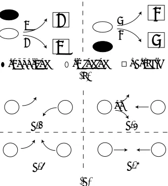
The characteristics of the avoidance behavior can be separated into two types: that concerning the relation-ship between the legs and obstacle, shown in Fig.5(a); and that concerning the interactive avoidance, shown in Fig.5(b). First, the former additionally can be separated into four cases: avoidances to the right or the left with the right idling leg, avoidances to the right or the left with the left idling leg in an adverse direction toward the obstacle. Secondly, the cases of interactive avoidance can be considered when a pair of moving objects walks head-on into each other. The possible situatihead-ons for interactive avoidance also have four cases. As shown in Fig.5(b),the cases of 1 and 2 are without collision; the cases of b-3 and b-4 have a high possibility of collision. Especially, the case of b-3 actually happens very often when two men walk head-on into each other. Interactive avoidance should be considered for collision avoidance control with the robot.
D
C
C D
B
A
A B
(a)
(b) or
b-1 b-2
b-4 b-3
swinging
supporting obstacle
Figure 5: Characteristics of avoidance behavior
3.2
Collision Avoidance Condition
Regarding collision avoidance control, we must con-sider real time judgments about whether or not there is a possibility of a collision in the future. In our method,by using the relative position and relative velocity between a pedestrian and a moving robot, judgments about the possibility of a collision are executed. In Fig.6 these for the robot are shown. Let the argument of the relative ve-locity of idling leg for the robot beψ(t). The argument of the two tangents from the point where the idling leg starts its swinging to the collision judgmental circle of the robot with a radiusDR are, respectively,φa andφb,
φa< φb. The reference line of the arguments ofψ(t),φa
andφbis the direction of movement of the robot. We can
see that if Eq.(17) is satisfied, a collision will not occur in the future. The condition for the possibility of a collision is Eq.(18).
ψ(t)< φa or φb< ψ(t) (17)
φa≤ψ(t)≤φb (18)
By setting the area with a certain amount of width along the direction of the robot’s movement, the control method is switched to a superior one on the inside or outside of the area. If it is inside, our proposal method is applied; if it is outside, the acceleration and deceleration method that is previous method[3] is applied.
!" # !"
$ !"
%'&(*)+*,.-0/21354 6879
[image:4.595.321.533.290.486.2]%'&:/*)79<;0&:/*&3
Figure 6: Direction of relative velocity
3.3
Avoidance Starting Point
Voluntary Guidance Type Collision Avoidance is a method that the robot executes avoidance behavior be-fore a human based on the walking pattern estimation, and motivates a human to carry out safety avoidance, as in Fig.5 b-1. We realize that the timing of the robot to start avoidance is important.
[image:4.595.86.252.361.545.2]in which it is impossible for the pedestrian to avoid a col-lision: this is where the idling leg is landing and where constraints on both feet prevent the pedestrian from be-ing able to apply force to the next idlbe-ing leg. By the robot starts to avoid a collision in this instance, the safe direction of the interactive avoidance is indicated to the pedestrian. According to the reasoning above, the in-stance in which the idling leg is landing is defined as the avoidance starting pointtavo.
3.4
Avoidance Condition Algorithm
When the robot detects a pedestrian, the Avoidance Condition Algorithm is applied. The system outline is shown in Fig.7.The motion of both legs is estimated by the Kalman Filter. Then after determinations regarding the idling leg or supporting leg and right or left, which stage the pedestrian is in can be estimated. After the stages are estimated, the avoidance starting point tavo
and direction of avoidance turning are generated.
LPF Kalman Filter if (Left Leg & Supporting Leg)
if (Right Leg & Idolling Leg)
if (Right Leg & Supporting Leg)
if (Left Leg & Idollinging Leg)
Stage 1
Stage 4
Stage 3
Stage 2
Stage discerning
k
position v
Stage
po
W
o W
p o W
vl W
p
l W
vr
W
pr
W
Avoidance Direction
angular velocity
<̆ a b<̆
if , 1
R g
<
̆
a b
2
a b
if
2 a ,
a b
2 <̆
a b
if
2 b , k - 1
,
k
( )
k
( )
k
( ) k
( ) avo k = t
avo k = t
avo t <k< T
( ) , ( )k
avo
t <k< T ( )k - 1
k
( )
k
( )
k
( )
k
( ) ( )k k
[image:5.595.55.284.323.486.2]( )
Figure 7: System of obstacle avoidance
The idling leg or supporting leg is determined with a threshold. For the time k, let the velocity of the idling leg and the threshold, respectively, be v(k) andvmin; if
v(k) > vmin, it is the idling leg;if v(k) < vmin. it is
the supporting leg. The right or left is determined by the argument θ(k). The argument between the segment connecting the last measured point of the supporting leg with the current point of the idling leg and the direction of movement is calculated by Eq.(19); ifθ(k)>0, it is the right; if θ(k)<0, it is the left. The condition Eq.(19) is effective under the collision possibility condition Eq.(18). The stage identification is completed by the integration of determinations.
θ(k) = tan−1pidly(k)−psupy pidlx(k)−psupx
(19)
Finally, we expound a method of determining the
turn-ing direction of robot. When the collision possibility con-dition Eq.(18) is acknowledged, the turning direction is derived by the relationship between the walking direction ψ(k) andφa(k) andφb(k) at the avoidance starting point
tavo. To satisfy Eq.(17) making a comparison between
φa(k)−ψ(k) and ψ(k)−φb(k), a lower deviation is
ap-plied. Turning toward the avoidance direction is executed duringtavoto a walking cycleT; the turning angular
ac-celeration is kept till tavo+T, as shown in Eq.(21) and
Eq.(23). If Eq.(18) is satisfied after tavo+T, a recovery
motion in a direction toward the destination is executed as Eq.(24), where c1>0 andc2>0.
if φa≤ψ(k)< φa+φb−2φa
k=tavo , ωk=c2(φak−ψk) (20)
tavo< k≤T , ωk=ωk−1 (21)
if φa+φb−2φa ≤ψ(k)< φb
k=tavo , ωk=c2(ψk−φb) (22)
tavo< k≤T , ωk=ωk−1 (23)
if ψ(k)≤φa , φb≤ψ(k)
ωk=c1 Rθg (24)
4
Experimental Result
[image:5.595.328.528.554.655.2]This section presents a verification of our pro-posed method with a 2-wheel drive robot (Power-Bot/MobileRobots,lnc., equipped with a laser sen-sor/SICK,Co.). The shortest distance to an obstacle and its argument can be measured by a laser sensor. As shown in Fig.8, this laser sensor is mounted on front of the PowerBot, can site horizontal surface 0.1[m] high from the floor, can measure position of around an ankle.
Figure 8: Measurable height of laser sensor
1 1.5 2 2.5 3 3.5 4 4.5 5 1.0
2.0 3.0 4.0 5.0
Positio
n
x
[m
]
1 1.5 2 2.5 3 3.5 4 4.5 5 0
0.1 0.2
Time[s]
Positio
n
y
[m
]
Left Leg Right Leg Sensor Data Robot Landing point of
[image:6.595.307.546.75.364.2]Right Idoling Leg
Figure 9: Experimental result of timing of robot turning.
The filtered trajectories of both legs and a trajectory of the robot are shown. We can see a landing point of the right idling leg at around 2.0[s] because the measured position of the right leg is constant during from around 2.0[s] to 2.3 [s], i.e., this period is in Stage 3. Simultane-ously with this, the robot starts to turn toward the left side of pedestrian. Successive pictures of another result is shown in Fig.10. Here, when the left idling leg lands, the robot starts to turn right. Because of this, we can see that causing the pedestrian to turn right with the right idling leg is achieved. The effectual avoidance direction is generated by the avoidance condition algorithm and so collision avoidance is achieved with safety timing by voluntary guidance.
5
Conclusions and Future Work
It has been shown in this paper a collision avoidance control method with a autonomous moving robot consid-ering interactive behavior between robot and pedestrian. The avoidance starting point and the conditions to avoid a collision and to estimate the states of pedestrian is de-rived by an analysis of the walking pattern and avoidance behavior. We proposed a method that motivates pedes-trians to carry out the voluntary behavior by indicating the direction of interactive avoidance to pedestrian. Fi-nally, we verified the applicability of our method by ex-periments with actual equipment.
Future work will involve the expansion of applications to cases where there are over two pedestrians and in which the walking pattern is not a biped but that of an animal. To improve the accuracy of estimations, the use of a
"!#$%'&())
*+%-,.%/0$21(345 "!#$%-&672
8:9;0<9=?>)@9A
8:BDC:CED<9FG:HI=(>2H
Figure 10: Experimental result with sufficient turning speed
work system with several laser sensors may be effective.
References
[1] W. Huang, B. R. Fajen, J. Fink and W. H. War-ren, “Visual navigation and obstacle avoidance us-ing a steerus-ing potential function,”Robotics and
Au-tonomous Systems, 54(4), pp. 288–299, 2006
[2] H. Koyasu and J. Miura, “Mobile Robot Motion Planning Considering Path Ambiguity of Moving Obstacles,”Proc. of the 9 th Int. Conf. on Intelligent
Autonomous Systems, pp. 85–93, 2006
[3] T. Minami, K. Tsushima, “Moving Obstacle Avoid-ance based on Speed Control without Changing Trajectory of Autonomous Mobile Robot In Case of Considering Dynamics of Robot(in Japanese),”
Proc. of 2004 JSME Conf. on Robotics and
Mecha-tronics, Paper No. 1P1-L1-70 (CD-ROM), 2004
[4] H. Zhao and R. Shibasaki, “A novel system for track-ing pedestrians ustrack-ing multiple strack-ingle-row laser-range scanners,” IEEE Trans. on Systems, Man and
Cy-bernetics, 35, pp. 283–291, 2005
[5] S. Mochon and T. A. McMahon, “Ballistic walking,”
[image:6.595.54.283.78.321.2]