1
Abstract
This thesis showcases the development process of a tool for achieving a sustained, non-percussive sound that captures the sonic essence of ceramic objects, a so-called ‘sonic screwdriver’, meant for
2
Acknowledgements
3
Table of Contents
Abstract ... 1
Acknowledgements ... 2
List of Figures ... 6
1 Introduction ... 8
2 State of the Art on sustaining sounds in ceramic materials... 10
2.1 Introduction ... 10
2.2 Background research ... 10
2.2.1 Introduction ... 10
2.2.2 Audio feedback ... 10
2.2.3 Methods of Feedback Control ... 11
2.2.4 Conclusion ... 12
2.3 State-of-the-art review ... 13
2.3.1 Introduction ... 13
2.3.2 EBow ... 13
2.3.3 Koka’s Magnetic Bow ... 16
2.3.4 The Sound of Ceramics ... 16
2.3.5 Ceramic Sound Art Instruments ... 17
2.3.6 MIDI Sprout ... 19
2.3.7 Conclusion ... 20
3 Methods & Techniques ... 21
3.1 Introduction ... 21
3.2 Ideation ... 22
3.2.1 Scientific literature research ... 22
3.2.2 Co-design ... 22
3.3 Specification ... 22
3.4 Realization ... 23
3.4.1 Building prototypes ... 23
3.4.2 Laboratory experiments ... 23
4 Ideation ... 24
4.1 Introduction ... 24
4.2 Stakeholders ... 24
4.3 Brainstorming ... 25
4
4.5 Preliminary requirements ... 26
4.6 Building plans ... 26
5 Specification ... 27
5.1 Introduction ... 27
5.2 Object sonification ... 27
5.3 Excitation ... 29
5.3.1 Introduction ... 29
5.3.2 Surface transduction ... 29
5.3.3 Conclusion ... 34
5.4 Pickup ... 35
5.4.1 Introduction ... 35
5.4.2 Condenser microphone ... 35
5.4.3 Magnetic coil pickup ... 35
5.4.4 Laser microphone ... 36
5.4.5 Hall effect sensor ... 37
5.4.6 Contact microphone ... 38
5.4.7 Conclusion ... 41
5.5 Amplification ... 41
5.5.1 Introduction ... 41
5.5.2 Audio interface ... 41
5.5.3 DIY audio amplifier circuit ... 41
5.5.4 Choice ... 43
5.6 Feedback control ... 44
5.6.1 Corpus-based method ... 44
5.6.2 Analog method ... 44
5.7 System requirements ... 45
6 Realization ... 47
6.1 Introduction ... 47
6.2 (Pre-)amplification ... 47
6.3 Shock mount design ... 48
6.4 Setups ... 50
6.4.1 Experiment 1 ... 50
6.4.2 Experiment 2 ... 51
5
6.5 Characteristics of surface transducers ... 53
7 Evaluation ... 55
7.1 Introduction ... 55
7.2 Discussion of experiments ... 55
7.2.1 Experiment 1 ... 55
7.2.2 Experiment 2 ... 55
7.2.3 Experiment 3 ... 55
7.3 Requirements check ... 56
8 Conclusion ... 58
9 Future Work ... 60
Appendix I ... 61
Experiment 1: determining the resonant frequencies of a feedback loop ... 61
Introduction ... 61
List of components ... 61
Method ... 61
Results ... 62
Conclusion ... 63
Appendix II ... 64
Experiment 2: resonant frequencies & gain phase analyzer ... 64
Introduction ... 64
List of components ... 64
Method ... 64
Results ... 66
Conclusion ... 71
Appendix III ... 73
Experiment 3: controlling feedback with control signal of desired pitch ... 73
Introduction ... 73
List of components ... 73
Method ... 73
Results ... 75
Conclusion ... 75
6
List of Figures
Figure 2.1: Edwin Dertien's 24V LED dimmer board. ... 13
Figure 2.2: An EBow placed on an electric guitar. ... 14
Figure 2.3: a high-level overview of an EBow. Figure 2.4: underside of an EBow. ... 15
Figure 2.5: DIY-schematic of an EBow. ... 15
Figure 2.6: Left: Koka's Rotary Magnetic Bow full setup, right: close-up shot of the rotary bow. ... 16
Figure 2.7: The Sound of Ceramics. ... 17
Figure 2.8: From left to right: The Egg, The Trunk, and The Shroom by Fedde ten Berge. ... 18
Figure 2.9: a graphic overview of Bela. ... 19
Figure 2.10: MIDI Sprout interfaced with a MacBook Pro via MIDI over USB and electrodes placed on a plant as input. ... 20
Figure 3.1: The design process of Creative Technology [30]. ... 21
Figure 4.1: X ways to break a ceramic plate. ... 25
Figure 5.1: Ceramic artifact during Daniël Maalman's artist-in-residence program at ekwc. ... 28
Figure 5.2: Grocier Innovation 256mm porcelain dinner plate. ... 28
Figure 5.3: 8TET1 by Daniël Maalman ... 29
Figure 5.4: Simplified anatomy of a standard loudspeaker. ... 30
Figure 5.5: Bottom plate with spacers on the left, top plate with surface transducer and contact microphones on the right. ... 30
Figure 5.6: Adafruit Medium Surface Transducer. ... 32
Figure 5.7: Adafruit Large Surface Transducer. ... 32
Figure 5.8: Equal loudness curves by Robinson and Dadson, 1956. [36]... 33
Figure 5.9: Adafruit Medium Surface Transducer frequency response graph [37]. The large ‘PASS’ means that this transducer passed some sort of quality control, it has nothing to do with filtering. ... 33
Figure 5.10: Adafruit Large Surface Transducer frequency response graph [38]... 34
Figure 5.11: Studio Projects B1 condenser microphone. ... 35
Figure 5.12: frequency response curve of the Studio Projects B1. ... 35
Figure 5.13: Inside of a single coil guitar pickup... 36
figure 5.14: Setup of a laser microphone [39]... 37
Figure 5.15: A linear Hall effect sensor. ... 37
Figure 5.16: Diagram that shows how a Hall effect sensor works. ... 38
Figure 5.17: A Snark SN-8 clip-on tuner. ... 39
Figure 5.18: The inside of a Snark clip-on tuner, with the location of the piezo disc clearly visible. ... 39
Figure 5.19: SoniPhorm magnetic contact microphone [40]. ... 40
Figure 5.20: Dedicated Omnia pre-amplifier on the left, accelerometer-based contact microphone on the right [41]. ... 40
Figure 5.21: A build of Evan Kale's tin can amplifier. ... 42
Figure 5.22: circuit of Evan Kale's tin can amplifier build. ... 42
Figure 5.23: A schematic of a voltage divider. In the case of an amplifier input, its input impedance is Z2. This means that the lower its value, the lower Vout will be. ... 43
Figure 5.24: Operational Amplifier in buffer configuration. ... 43
Figure 5.25: HP 33120A function generator. ... 45
Figure 6.1: Focusrite Saffire PRO 14 FireWire audio interface. ... 47
Figure 6.2: shock mount test setup for ceramic plate... 49
Figure 6.3: CorelDRAW X7 design file of the shock mount. ... 49
7
Figure 6.5: Graphical overview of the block diagram of the setup in experiment 1. ... 50
Figure 6.6: Block diagram of the setup of experiment 1, the arrows signify the travel of sound. ... 51
Figure 6.7: Graphical overview of the block diagram of the setup in experiment 2. ... 51
Figure 6.8: Block diagram of the setup of experiment 2, the arrows signify the travel of sound. ... 52
Figure 6.9: Graphical overview of the block diagram of the setup in experiment 3. ... 52
Figure 6.10: Block diagram of the setup of experiment 3, the arrows signify the travel of sound. ... 53
Figure A1.0.1: Mounting the piezo disc mounted on the rim of the dinner plate. ... 61
Figure A1.0.2: Placing the surface transducer under the plate. ... 62
Figure A1.0.3: Oscilloscope view of the produced audio feedback using the medium surface transducer.62 Figure A1.0.4: Oscilloscope view of the produced audio feedback using the large surface transducer. .... 63
Figure A2.0.1: One of the used test setups, this iteration with a large surface transducer and a large piezo disc. ... 65
Figure A2.0.2: Large Surface transducer on plate at 20dB attenuation, large piezo... 66
Figure A2.0.3: Large Surface transducer on plate at 0dB attenuation, large piezo... 66
Figure A2.0.4: Medium surface transducer on plate at 0dB attenuation, large piezo. ... 67
Figure A2.0.5: Medium surface transducer on plate at 20dB attenuation, large piezo. ... 67
Figure A2.0.6: Large surface transducer on plate at 0dB attenuation, small piezo. ... 68
Figure A2.0.7: Large surface transducer on plate at 20dB attenuation, small piezo. ... 68
Figure A2.0.8: Medium Surface transducer on plate at 0dB attenuation, small piezo. ... 69
Figure A2.0.9: Medium Surface transducer on plate at 20dB attenuation, small piezo. ... 69
Figure A2.0.10: Influence of placement of the surface transducer on the produced bode plot. ... 70
8
1
Introduction
Sound art is a relatively young art discipline, with the origin of the definition going back only to between the 1910’s and the 1930’s. Camilo Salazar, manager of Music Technology program at Morley College London describes it as “an art form that focuses on sound as a fundamental element”. He adds that it is an everchanging definition as with time, more and more genres are already categorized as sound art [1]. It is often combined with elements of visual art and/or experimental music.
Because sound is at the center of the latter too, it is easy to confuse sound art with music. In general, it can be said that music can be a form of sound art, but not all sound art is considered music [2]. Oftentimes, music is more time- and melody-focused than sound art, though this is not always the case; there is some overlap between the two and many sound artists are also musicians, causing musical aspects or elements to often be present in sound art.
One such sound artist who is a musician as well is Daniël Maalman. Maalman is an AKI Academy of Fine Arts Enschede graduate (2010) who is specialized in building temporary sound art installations based on spaces and sites. In his works, among which Lost & Found Orchestra (2015), he aims to uncover hidden sounds in materials and objects. As Maalman is a musician too, he tends to use these hidden sounds for musical purposes, by using them in compositions for example [3]. One typical example of how he does this is his series of Lost & Found Orchestra installations, in which the objects and the space they are placed in act as the instruments. The objects or space produce sounds by being tapped on by different actuators such as solenoids or vibration motors, for example. These actuators are controlled in real-time from a central MIDI trigger board, creating sounds with the objects. A mix of this ‘orchestra’ is created by feeding contact microphones (or: piezo discs) that are placed on the surface of objects into a mixer, allowing post-processing of the sounds. [4] Because Lost & Found Orchestra is meant as an installation that the spectator can walk around in as it is being played, all the actuators have an LED attached to them that lights up when activated, so that the spectator can see more easily where each sound that they hear is coming from exactly. Here too, sound art is combined with visual aspects.
Both Lost & Found Orchestra and his artist residencies at ekwc (European Ceramic Work Centre) and STEIM (Studio for Electro-Instrumental Music) serve as the research phase for a next project called Foundscape. At ekwc, Maalman researched the effects that the type and shape of ceramics would have on their sonic properties. At STEIM, he researched the ways in which ceramics can be excited to produce sounds, for example with which actuators. One of the aims of Foundscape is for Maalman to develop his own electronic toolkit for use in sound art projects. This is where the Sonic Screwdriver comes in. The project description was as follows [5]:
“LFO is a project by sound-artist Daniel Maalman who is currently doing residency project at EFKW and later this year at STEIM. For this assignment a universal multi-channel midi trigger board needs to be developed which can use different types of actuator to tap, stroke, rattle and otherwise make objects release inner hidden sounds. In the same system a pickup (microphone, piezo, etc.) will be interfaced allowing audiosonic feedback. Basically, you are designing a swiss army knife of sound - or 'sonic screwdriver' if you like.”
9
reverberation within the object or effects added in post-processing. The produced sound decays quite quickly and the amount of sounds that can be produced with the actuators is rather limited.
As all art is a form of personal expression, it is quite necessary to have a very flexible toolkit, so that the artist has optimal creative freedom and does not have to worry about not being able to properly express themselves because of limitations imposed by the tools used. In case of a painter for example, this could mean having a large collection of different paint brushes. In the case of sound artist Daniël
Maalman, it means a more flexible method of creating sounds using ordinary objects as musical instruments than simply hitting an object repeatedly. That is why the research question is as follows:
How can a sustained, non-percussive sound be produced from a ceramic object, in which only the characteristics of this specific object determine the tone?
10
2
State of the Art on sustaining sounds in ceramic materials
2.1
Introduction
In this chapter, two things will become clear. The first one is the theory of the workings behind sustaining a sound that is produced in an object, the second one is the practical applications of this theory that is presently already in use in products and projects. This will be done by means of a scientific literature analysis first, followed by a state-of-the-art analysis.
2.2
Background research
12.2.1
Introduction
There are many ways to sustain a sound. One type of sound that has a long decay time by definition is audio feedback, which can theoretically have an infinite sustain and is also very employable and usable in a musical context, as shown by The Beatles and Jimi Hendrix, to name a few. This literature research aims to give the reader insight in the different ways in which audio feedback can be controlled and used musically in sound art installations in order to allow for more sonic flexibility in sound art pieces. Towards this purpose, a definition of audio feedback will be given first. After that, an overview of the means in which audio feedback can be controlled will be given and finally, a conclusion will be drawn about what the best way to control audio feedback is.
2.2.2
Audio feedback
To find a way to expand the musical palette of a sound artist by means of audio feedback, a clear understanding of what exactly feedback is, is necessary. As also cited in Kollias [6] and Ferguson et al. [7], Morris [8] discerns three different types of feedback:
1. Electronic feedback, the most basic type. It occurs when the output of an electronic circuit is directly connected to the input of a circuit as a signal, making the signal enter the system again, but with some small delay. Electronic feedback makes for a highly predictable signal.
2. Digital feedback. This type uses data within one software program or between multiple programs as an input and output, rather than physical signals.
3. Electroacoustic feedback, the most relevant type for this paper. This is also the type musicians simply refer to as feedback or audio feedback. It occurs when the output of a circuit is connected to an actuator such as a simple speaker, instead of being connected directly to the input of the same circuit. The signal that the speaker produces is picked up by a sensor such as a microphone, which is connected to the input of an audio amplifier that outputs the received signal to the same speaker again. In electroacoustic feedback, the delay from the output back into the input is determined by the distance between the speaker and the microphone among others. This process produces the so-called Larsen effect, which results in a sustained high-pitched sound.
1 This section is largely part of the literature review project for the course 'Academic Writing'. It has been
11
Audio feedback is usually considered undesirable, as it often tends to be distracting and unpleasant to the ear. One such example is when it occurs as a loud squeal in a PA system when somebody is trying to publicly address a crowd[9]. In this research though, it is actually desired because producing audio feedback is a requirement for the solution.
Morris [8] also adds that electroacoustic feedback can make for much more complex and less controllable results than electronic feedback, because the environment that is between the speaker and microphone are placed in can heavily color the original signal before it is picked up by the microphone. One example of this comes from Lucier [10] in the form of a sound art piece that was created by
iteratively recording himself reciting a text. Lucier made one recording of himself, which he then played back over speakers to record it again. He would then play back the next recording and record it, et cetera. After a couple of minutes, the recited words started becoming less and less intelligible, because the resonances that were created by characteristics of the environment had taken over and eventually became all that can be heard. To conclude, there are three different types of feedback, of which electroacoustic feedback is the one that is used in music the most.
2.2.3
Methods of Feedback Control
The lack of control over the outcomes of electroacoustic feedback makes it hard to use predictably, which is an undesirable trait when approaching it from a musical perspective because musical instruments traditionally have a highly predictable relationship between control input and sound output [7]. There are different ways of controlling electroacoustic feedback for use in musical context, each with varying degrees of success. Di Scipio [11] presented his attempt at controlling feedback, which he achieves by means of digital signal processing (DSP) on a computer. The DSP algorithm dynamically adjusts itself based on the input signal. The algorithm controls the gain of the feedback, which keeps the system in equilibrium volume-wise. He claims that this way, he uses sound as both content for listeners and as a control signal for the feedback gain of the audio feedback [12][13] Similarly, Ferguson et al. [7]
controlled the gain of a bandpass filter using a DSP algorithm to steer the pitch of the audio feedback of a guitar and an amplifier. However, this did not guarantee the specified pitch to be produced, as the strings may not have a natural resonance at this pitch. The approach of choosing sonic features to make the audio feedback conform to was also proposed by Kim et al. [14] by means of evolutionary control of second-order structures.
Kollias shows a similar view to Di Scipio regarding letting sounds control themselves by using them as a control signal for DSP, as well as the focus point for the listener. However, he argues that letting the sound only control the feedback gain grants almost no control of the overall sonic shape of the feedback[15]. [6], [9], [15], [16] and [17] propose a system of self-organizing sounds, a term that Kollias invented himself. He explains this term as “‘intelligent’ sound/music systems characterized among others by autonomy, distributed/decentralized feedback processes and of environmental awareness”[2, pp. 1]. He invented this term to prevent any confusion that might be caused by the overuse of the word ‘feedback’ in the many different fields of science [6]. While Di Scipio’s system is technically self-organizing according to Kollias’ criteria, its implementation is quite elementary and lets many opportunities for controlling different aspects of the sound go to waste [15]. However, Di Scipio, Morris [18] and Hayes & Stein [19] and argue that this lack of control over the feedback simply puts the traditional role of composer of music into the hands of sound itself, sidelining the actual composer as merely the engineer of the dynamical feedback control system [12].
12
characteristics of the acoustic environment to further control the sound of the audio feedback. The DSP algorithm is updated in real-time based on the audio that is connected to the input of the system, after which it takes this signal, modifies it, and outputs it. In this system, the room reverberation can control the tempo-scale characteristic, the ambient noise level can control the amplitude and the resonances of the acoustic environment determine the timbre (energy distribution over frequency spectrum) of the audio feedback. Just as Ferguson et al. [7], Kim et al. do warn that despite a sophisticated DSP algorithm, audio feedback is still hard to control, as a very slight increase of gain or decrease of distance between speaker and microphone can already violate the Barkhausen stability criterion. This is the criterion that is required for oscillation and thus producing audio feedback [20]. Feedback can still not be predicted accurately short-term due to nonlinearities, though long-term tendencies can be predicted.
Additionally, Morris [8] proposes the option of iterative feedback to give the artist more control over the output, by which he means a feedback process that is not necessarily implemented in real-time, but can also be implemented afterwards in editing. An example of iterative feedback is the
aforementioned I Am Sitting In A Room [10]. To conclude, the ways in which audio feedback can be controlled are various types of gain-adjusting DSP algorithms, DSP algorithms that model characteristics of the acoustic environment, and iterative feedback.
2.2.4
Conclusion
In conclusion, though there are in fact ways to control audio feedback predictably, there are relatively few, each with varying degrees of success. It seems that most options involve the use of computers, be it for dynamically adjusting DSP algorithms or iterative feedback. Audio feedback remains an unpredictable phenomenon due to the enormous impact that even the smallest of changes to the acoustic environment can have on the produced sound, making accurately controlling it for musical purposes quite the challenge. While iterative feedback grants the artist the most precise control over the final produced sound, the process takes quite long, making it unsuitable for live performances. DSP algorithms are the best option for real-time usage. These algorithms can range from simple general gain adjustment for automatic amplitude control, to more intricate band pass gain adjustment for pitch tendency control, to complex acoustic environment characteristic modeling, with which tempo-scale characteristics, amplitude and timbre of the audio feedback can be controlled fairly precisely.
However, not every single adjustment option is completely necessary for a sound artist and having too many options may harm the user-friendliness of a system. For the Lost & Found Orchestra, the only set-in-stone requirement is real-time operation. That is why a band pass gain adjustment DSP
algorithm would likely be the best fit for the Lost & Found Orchestra: it is a fairly flexible and precise control method, while not being too intricate to use.
For further research, the next step would be to look into options for a DSP system that allows control of as many feedback controlling parameters as possible, both automatically and by hand.
Automatic parameter control could then be achieved by means of preset selection by the user, after which the resulting feedback sound will simply behave a certain way at the push of a button. For manual
13
2.3
State-of-the-art review
2.3.1
Introduction
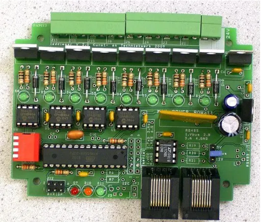
[image:14.612.74.340.263.489.2]Currently, a multi-channel MIDI trigger board is implemented [21]. Currently, a Korg nanoKONTROL Studio sends MIDI data to a computer that converts the data to RS-485 and sends it to a custom-made 24V LED dimmer board (Figure 2.1). Different types of actuators can be connected to the output of the dimmer board, which can then all be controlled individually using MIDI signals. As mentioned before, solenoids are usually used for this purpose, but they solely rely on impact for the production of sound. In this chapter, examples of technologies currently in use are analyzed. They already conform to certain aspects that the final product of this graduation project should conform to as well in their current form. While none of them are exactly the solution to the research question, as that would make this research pointless, and they all have their own limitations that make them unsuitable solutions, these technologies will be discussed in this chapter to draw inspiration from.
Figure 2.1: Edwin Dertien's 24V LED dimmer board. 2
2.3.2
EBow
The EBow (Figure 2.2), short for ‘electronic bow’ or ‘energy bow’, is a device for use on electric guitar. It was invented in 1969 by Greg Heet and is currently produced by Heet Sound Products in Los Angeles. What it does, is make a guitar with metal strings produce sounds on one string without the use of a
plectrum. The sound that is produced with it is often compared to the sound that is achieved when running an actual bow (such as the one used on a violin or a cello) across the strings of the guitar, hence the name.
2 Source:
14
Figure 2.2: An EBow placed on an electric guitar.3
The way it works is as follows: as can be seen in Figure 2.2, the device has both an input coil and an output coil that are placed at a fixed distance from each other, at which they do not directly interfere with each other. Meanwhile, a guitar string is held perfectly centered along the same axis as the coils, also at a constant distance from the coils because of the string guides underneath the device ( Figure 2.4) which hold on to the two neighboring strings, also silencing them. The two coils are connected to a LM386 low voltage audio power amplifier, which is an amplifier integrated circuit that requires very few external components (Figure 2.5). It runs on a standard 9V battery. Because of the magnetic field that is created by the circuit, the guitar string will start to vibrate and because of the feedback loop, this vibration will provide an input for the circuit, which will make the output coil produce a new magnetic field and keep the string vibrating for as long as the user wants or until the battery runs out.
Moving the device along the strings will allow the user to discover a place where they like the produced feedback sound best and find other sweet spots. For electric guitars, this is usually near one of the magnetic pickups, for acoustic guitars, it depends. The constant distances between the three main components responsible in the production of sounds, namely the input coil, output coil and the string, makes this audio feedback loop one that is very predictable and controllable. This is something that is rarely seen in audio feedback.
15
Figure 2.3: a high-level overview of an EBow.4 Figure 2.4: underside of an EBow.5
Figure 2.5: DIY-schematic of an EBow.6
The EBow allows for a lot of sonic flexibility for guitarists: the user guide describes it as “virtually an instrument in itself”. It also provides plenty of examples for different playing techniques and even mentions ways to use it to make an electric guitar sound like a flute, cello, horn or harmonica [22]. This flexibility is very relevant to the current research. The small form factor is a big plus too and the ergonomics make for an intuitive user experience. It would seem that the EBow checks all the boxes of the project requirements. However, the tonal flexibility when used on guitar is also the device’s main downside: due to its design, it only works on metal-stringed instruments. This makes it useless for this project in its current state, as the material that needs to produce a sound is ceramic. It could be that adding metal to the ceramic would allow it to be manipulated with the EBow, but that requires further research. What could potentially be useful in
4 Source: https://www.youtube.com/watch?v=98zGR3QSJ74 5 Source: https://buzzmusic.co/products/ebow
16
finding a solution is to build the EBow circuit on a breadboard and experiment with different types of sensors and actuators connected to the input and output of the circuit.
2.3.3
Koka’s Magnetic Bow
Koka Nikoladze is a well-known Georgian sound artist. Just as Maalman, Nikoladze is a musician too. His sound art therefore incorporates musical elements as well. For example, he makes his own musical instruments and even small boxes with all kinds of objects inside and on top that play a small composition when turned on. He calls these boxes Beat Machines. One of the musical instruments that he made is called Koka’s Propeller Trinity, which uses a propeller for generating many types of different sounds. Included in the trinity is Koka’s Rotary Magnetic Bow [23], which, as the name implies, uses permanent magnets mounted on a rotating disk (Figure 2.6). According to Nikoladze, when the magnets spin in front of any musical instrument, it causes a magnetic oscillation, which can be controlled by changing the rotation speed, which is controlled with a fader-type potentiometer. By changing the magnetic oscillation, different frequencies can be targeted and resonate [24]. For example, when placed in front of a plugged-in electric guitar as showcased in his demonstration video, a droning sound is created that can go on for as long as the artist wants it to. The bow seems to have to be mounted at a fixed distance from the
instrument, which does make for very stable audio feedback.
Figure 2.6: Left: Koka's Rotary Magnetic Bow full setup, right: close-up shot of the rotary bow.7
The form factor of the device is quite small, and it features a convenient mounting hole for attaching it to a microphone stand. Though the stable audio feedback is a desirable feature, the pitch control of the device leaves a bit to be desired as the pitch is almost entirely determined by adjustment of a potentiometer. Though intuitive, this is quite an imprecise method. Of course, by replacing the regular potentiometer with a digital one, it can be adjusted precisely, but the sound that is produced at a different setting will differ heavily based on what instrument the device is used on. It is hard to determine if the device is easy to integrate in other types of setups, as the only currently known instance of Koka’s Rotary Magnetic Bow being used is in the demonstration video on an amplified electric guitar. Even though it does not conform to all requirements, this device is worth building as a test setup to get familiar with the way it works, for the purpose of sonification of ceramics.
2.3.4
The Sound of Ceramics
The Sound of Ceramics was an exhibition by Lu Wang and Polly Apfelbaum at Brown University, Rhode Island, which showcased the sonic properties of ceramics in different geometric shapes as they were
17
suspended from the ceiling with a wire (Figure 2.7) [25]. The pieces of ceramic material were used as a melodic percussive instrument during a performance, which was accompanied by prerecorded sounds produced by the same setup. Unfortunately, no footage of this exhibition of any sort could be found, so the way in which the shape of the ceramics influenced the sounds that they produced remains unknown. However, it would have been a good example of the sonic properties of ceramic materials.
Figure 2.7: The Sound of Ceramics.8
While ceramics are being used to create different types of sounds which are all easily and intuitively controllable, the sounds produced in this setup are all impact-based and decay quite quickly, just as in the current state of the Lost & Found Orchestra. Aside from this, the system is all but small and unobtrusive, and would be hard to integrate in a Lost & Found Orchestra in this form. However, this is not really a shame, as there is no added benefit in adding more objects in the Lost & Found Orchestra that produce sound in exactly the same way that the current objects already do.
2.3.5
Ceramic Sound Art Instruments
In 2016 and 2017, sound artist Fedde ten Berge created a few interactive ceramic sound art installations in collaboration with Frank van Os from Barst! Keramiek. The shapes of the installations invite viewers to touch them, after which the installation responds with amplified electronic signals applied to its surfaces, generating sounds while also showcasing the electronic properties and vibrating qualities of the used ceramics. The experience that is produced is different for every viewer. Three examples of these ceramic installations (Figure 2.8):
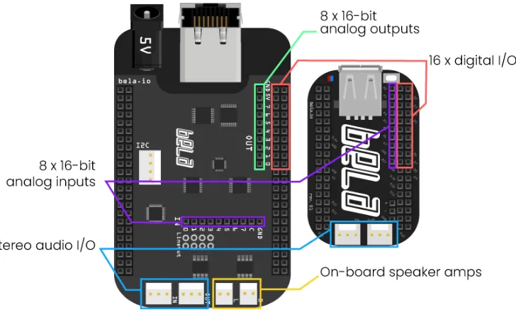
• The Egg. This installation starts to crackle when the viewer moves their hands closer to it. As they move their hands away, a chord is produced using phase aligned formant synthesis. When the viewer puts their hand in the water contained in the egg, the ceramic material will produce the loudest sound [26]. All this interaction is made possible by means of Bela (Figure 2.9), an
embedded computer platform that allows for digital interfacing of sensors in a low-level manner (not unlike Arduino), while simultaneously being capable of ultra-low latency on-board audio processing, which makes for interesting real-time interactive applications [27].
18
• The Trunk. Close proximity capacitive sensing is used for producing sounds in both the tree trunk and the ceramic water trays of the installation. The water triggers samples of water splashing when touched. The trunk is equipped with three piezo disks at the bottom, so that sounds produced by tapping on it can be extended into what seems to be infinity using software [28]. This extended sound is close to that what needs to be achieved on ceramics for this research.
• The Shroom. Another Bela-based artwork that uses sensors to sense different types of vibrations, such as electromagnetic or acoustic, but also material vibrations and responds to people
approaching it with different sounds. The ceramic dome has steel dust baked inside of it and as the inside is covered with aluminum foil, this makes for a capacitive proximity sensor. Also inside the bowl are electret microphones for picking up acoustic vibrations and piezo disks for picking up vibrations caused by knocking [29]. What type of actuators are used is currently unknown, but it could be worth getting into contact with the artist for this too, as this installation can create sustained ceramic sounds as well.
Figure 2.8: From left to right: The Egg, The Trunk, and The Shroom by Fedde ten Berge.9
19
Figure 2.9: a graphic overview of Bela.10
2.3.6
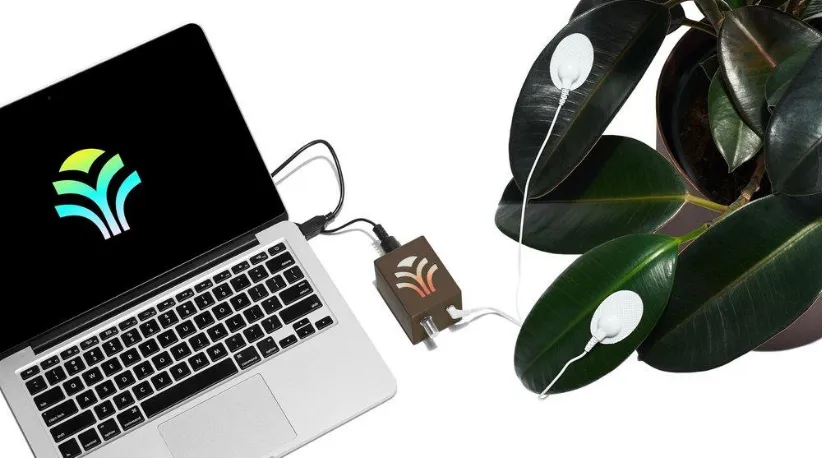
MIDI Sprout
A device developed by Joe Patitucci from zero-waste record label Data Garden, who try to combine electronic music and the environment to show a relationship between the two. The MIDI Sprout uses changes in conductivity on the surface of plant leaves combined with a complex algorithm to create music (Figure 2.10). This device has also sparked the advent of Plants FM, an online radio station that streams music generated by plants and the MIDI Sprout all day long. The usage of changes in conductivity of a surface for generating notes is an interesting concept for the Lost & Found Orchestra too. Through the aforementioned The Shroom, it became clear that the conductivity of ceramic clay can be changed by mixing it with something like steel dust before baking. If a way of changing the conductivity of already baked ceramics can be found, maybe such as bending it etc., this could be relevant for the Lost & Found Orchestra as well in some way, though not in the context of capturing the actual acoustic characteristics of a ceramic object, which is purely an acoustical context.
20
Figure 2.10: MIDI Sprout interfaced with a MacBook Pro via MIDI over USB and electrodes placed on a plant as input.11
2.3.7
Conclusion
What can be gathered from the state of the art is that there is a plethora of examples of products and projects that can make for sonification of a wide range of objects, but none of them are directly capable of solving the research question as-is. Elements from the working principle of the EBow can definitely be used to get an indefinite sustain, aspects of other projects such as Ten Berge’s involving conductivity less so. The remainder of this research will be dedicated to finding ways to sonify objects by implementing knowledge from the state of the art, such as constructing an EBow circuit and connecting different types of sensors and actuators to the input and output. At the very least, this analysis has given an insight in which techniques might not work as well, such as capacitive sensing.
21
3
Methods & Techniques
3.1
Introduction
[image:22.612.86.411.214.679.2]This chapter is devoted to the methods and techniques that will be put into practice to research audio feedback in ceramic objects. This will be done by means of the design process that is adhered to in most projects in the Creative Technology BSc. program that was designed by Mader and Eggink [30], which can be found in Figure 3.1. The methods will be named and explained, and the used research techniques that belong to these main methods will be listed in under the method they belong to.
22
3.2
Ideation
When looking at Figure 3.1, there is one design question that leads this project into the ideation phase, which is the research question of how to sonify ceramic objects in a non-percussive manner. In this specific project, the techniques used are user/expert interview (part of the co-design process that is required for this project, as it is made specifically for one sound artist) and sketches. Ideation is the phase of divergence, meaning that the territory of the design project, its boundaries and the project goals are defined by means of research. This research can be done via many means, such as surveys, focus groups literature study or lab experiments. Most of the research that needs to be done, is done in this phase. The goal is to make clear to the designer what exactly needs to be accomplished with the design challenge to make the design achieve its objectives. Eventually, a combination of a product idea and an interaction idea is what came out of this phase, which required some iteration when in the specification phase, it turned out that some of the preliminary requirements were either not feasible or not defined clearly enough.
3.2.1
Scientific literature research
Though some scientific literature analysis has been done already for chapter 2.1, the analysis of relevant literature is an iterative process that should occur in every chapter of any scientific publication, such as this graduation project. It helps the researcher stay focused and prevents a tunnel vision mentality, which could prevent the researcher from finding an answer to their research questions. New sources will be searched for as soon as a lack of scientific evidence for a statement occurs. In the process of analyzing this literature, interesting new findings will also be incorporated into this report, which may lead to new research questions.
3.2.2
Co-design
Co-design sessions need to take place, at which both the commissioner and student should be present. This session should serve to brainstorm and to discuss the view that both parties have on the project and if either of those views is realistic. A final design concept should be a project that still has the core
functionality of what the commissioner aims to achieve with the project, but it should also be feasible to make for the developer, which is in this case the student. Feasible is meant in both the sense of
completing the project in the given timeframe of 10 weeks, as well as it being realistically possible to make. The developer and the commissioner will work side by side and bounce ideas off each other as soon as they occur in order to gain new insights and work further from these insights.
3.3
Specification
23
computer simply applies a set of rules that it strictly adheres to so that no compromises will be made and the best product possible will be brought onto the market. If a certain value of a variable turns out not to be tolerable, the process will revert to the transformation stage and all variables and goals will have to be reconsidered. In this chapter, the main categories of components that should be used will be discussed and different for each of these categories will be compared. This will result in an updated version of the list of preliminary requirements, called the system requirements. In this project, these requirements were the product specifications and the interaction specifications. Co-design is used for defining these
requirements as well, as Maalman’s preferences are still very relevant here. Some light prototyping is done here as well to check for feasibility of using certain components and set specific goals for the prototype, but nothing concretely focused on answering the research question is built yet. This will have to wait until the realization phase
3.4
Realization
Based mostly on the requirements, thinking needs to be done about building prototypes that can be tested, so that eventually, a solution can be developed. It will turn out soon enough if the requirements that were set in the previous chapters are specific and concise enough, as if they turn out to be not, a prototype cannot be built properly. This is because it is impossible to leave too many variables to the imagination, as the prototype will likely not achieve the goal that it is set out to achieve.
3.4.1
Building prototypes
The insights gained during the scientific research will be used to select the working principles of an eventual end product, which will be thoroughly tested in isolation by means of various prototypes. Based on these principles, the appropriate components will be evaluated and selected for building the prototypes. Building prototypes is an iterative process, so if part of one of the prototypes turns out not to function as expected, it will be tinkered with to see the influences that that can have [30] and looked at scientific theory as to why something does not work the way that is expected.
3.4.2
Laboratory experiments
24
4
Ideation
4.1
Introduction
The ideation phase mainly focuses on designing with the stakeholder in mind, which is why they need to be interviewed. Some brainstorming will be done based on this, after which preliminary requirements can be set.
4.2
Stakeholders
The main target audience of the to-be developed technology is sound artists, making them a large stakeholder in this project. To get an accurate picture of exactly what they are looking for in this
technology, it is necessary to consult them in person. It is easy to make a technology very flexible and let the end user configure every parameter, but not all end users are equal, and some may have less of an understanding of the influence of certain parameters and may not be able to properly configure the system. This means that putting some constraints to the flexibility is necessary. To gain these insights, their previous work needs to be analyzed and interviews need to be scheduled with them. Interviews and co-design with Daniël Maalman himself and an interview with Jaap Mutter (an artist who has worked on numerous projects with Maalman) contributed the most information to the list of preliminary
requirements that will be mentioned later.
The designer of the system is the second large stakeholder in this situation. The designer or developer is also the person responsible for integrating measures to prevent abuse into the system. This is mostly because the designer does not want to be held accountable for anything that might go wrong while the product is being used by the end user, such as damage to either the user or their possessions. This is an incentive to make the product as safe to use as possible. One way of doing this is by significantly reducing the flexibility of the technology, so that the end cannot possible navigate themselves into any sort of dangerous usage scenario. The hard part is though, that the technology still needs to be flexible enough for the end user, as it has a purpose to fulfill as a creative tool.
Consumers of the art created with the use of this technology are the third stakeholder. Though not as important as the previous two, the final result of the usage of the technology should still be pleasing to the people who enjoy sound art. If it is not, they sort of become the victim of the developed technology and they will lose interest in the work of the artist, which in turn reduces the income of the artist. Polling whether they like the produced results or not is not the concern of the developer, but rather the concern of the sound artists, as after all, they are the ones responsible for making their own living. This stakeholder will not be taken into account for further development, as it is the responsibility of the artist to cater to their preferences.
25
4.3
Brainstorming
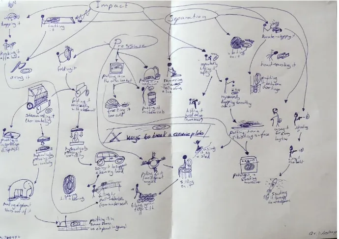
Brainstorming for possible solutions to the research question was done in a few different ways. In order to set the boundaries for what was possible to get sound out of a ceramic object, Edwin Dertien
[image:26.612.73.418.213.457.2]recommended making a morphological overview of ways to destroy a ceramic dinner plate. This morphological overview can be found in Figure 4.1. While being a lighthearted exercise, this diagram provoked thought about how all of these different methods of destroying a ceramic object would sound if they were to be executed in real life, most of which would not produce a long, sustained sound. Now that the boundaries were set for breaking a ceramic object, the working space for keeping a ceramic object intact in the process of producing a sound from it was defined.
Figure 4.1: X ways to break a ceramic plate.
4.4
Interviews
As is the case with co-design, carrying out an interview with the person by whom the design is going to be used. is extremely important, as they play a large role in determining the preliminary requirements and maybe even part of the system requirements. The interview with Maalman was not done in a traditional single Q&A session style, but rather by means of planning in parts of different days with him and playing around with his equipment while asking things that were unclear and Maalman telling things he thinks are important for the project. As such, this interview cannot possibly be documented as a traditional
interview. That is why the outcome of the interview is mostly summed up in the list of preliminary requirements. As Maalman is very experienced in the field of sound art, his opinions should be valued highly.
26
amplified signal, as it only has a certain bitrate and bit depth. An analog sensor simply produces a continuous output voltage, that would change smoothly depending on the distance of the plate. This would then have to be combined with a similar type of actuator to keep the object vibrating to obtain a sustained sound.
4.5
Preliminary requirements
The requirements below will be prioritized based on the MoSCoW principle as defined by Clegg and Barker [32]. MoSCoW is an acronym that stands for Must, Should, Could, Won’t, with the o’s added for pronunciation convenience. The musts are the main factors that determine whether the project can be counted as a success. If even one of these is not met, the project should be considered a failure. The should are the factors next in line of importance, but the project will not fail it they are not met. The coulds are aspects that could improve overall satisfaction with the result but are not considered critical and may be added if time and resources allow for it. The won’ts are aspects that have the lowest priority to be added and are therefore not included in the scope of the project. They will likely not be considered for a following iteration either. Requirements proposed by Maalman are in bold.
Musts:
• Plug & play for existing Lost & Found Orchestras
• Use the characteristics of the object itself in the produced sound
• Accurate pitch control • No damage to the object
Shoulds:
• Affordable • Expandable
• Easy to move around and remove
Coulds:
• Intuitive user interface • Portability
Won’ts:
• Control over the inherent resonant frequencies of a ceramic object.
4.6
Building plans
27
5
Specification
5.1
Introduction
5.2
Object sonification
The ways in which people have tried to sonify objects are plentiful. However, there are three elements that they all seem to have in common:
1. A source of excitation 2. A means of picking up 3. A means of amplification
Coincidentally, these are also the three main required components for an audio feedback loop, as mentioned in 2.3.2 and 2.3.3.
28
[image:29.612.72.436.72.341.2]Figure 5.1: Ceramic artifact during Daniël Maalman's artist-in-residence program at ekwc.
Figure 5.2: Grocier Innovation 256mm porcelain dinner plate.12
Maalman mentioned the following: there is a difference between ceramic material and the enamel coating. Both have an impact on the sound that is produced in the end. In 8TET1, he only used the ceramic material porcelain. Porcelain is made by adding powder to water with some other elements, which results in castable clay. The clay is then poured into a cast, which is then baked. The result is a finished ceramic object. Then, a mixture for enamel (a glass-metal composite [33]) is made, which is then slathered onto the baked ceramic object and subsequently baked at a slightly lower temperature to obtain a glossy finish. The enamels used all contain lead. The orange and yellow enamels seemed to pull the
29
material more and therefore break the ceramics more often than the blue and green enamels, which Maalman suspects has an effect on the sounds the ceramic can produce.
5.3
Excitation
5.3.1
Introduction
The source of excitation is the part that makes the surface of an object vibrate, which makes it produce sound. In Maalman’s Foundscape project: 8TET1, [34] he sonifies homemade ceramic plates by placing solenoid modules with springs attached above the plates. Using Dertien’s RS485-based 24V LED dimmer board [35], the solenoids are controlled via MIDI signals provided by Ableton Live. Based on the
[image:30.612.71.266.288.478.2]characteristics of the ceramic plates (types of additives used, such as lithium), the impact power of the solenoid, the tip used on the solenoid and the location where the ceramic plate is hit, a different sound will be produced. For example, most of the ceramic plates as seen in Figure 5.3 are hit with a small, rubber tip, but one of them is hit with a Dremel sanding tip, which produces a sound with many more higher harmonics. However, this is again a sound produced by means of impact.
Figure 5.3: 8TET1 by Daniël Maalman13
5.3.2
Surface transduction
When looking at a loudspeaker, the part that produces sound by moving up and down is the diaphragm of the speaker, which often has the shape of a cone, after which it is aptly named as can be seen in Figure 5.4. The cone should have a large surface so that a sufficient amount of air can be displaced.
30
Figure 5.4: Simplified anatomy of a standard loudspeaker.14
In the case of an object vibrating and therefore producing sounds, the object itself can be thought of as the diaphragm of a speaker. Instead of simply attaching a speaker to the object, there is a way to waste as little signal as possible. Removing the diaphragm results in a speaker that can be put onto any surface, which will turn that surface into a diaphragm. These types of speakers exist, and they are called surface transducers. One example of a surface transducer in use is the project called “IKEA plate reverb”, YouTuber LeoMakes actually uses the Adafruit Medium Surface transducer. In his initial setup, he bought two metal IKEA ‘BROR’ shelves and frames and modified them so that they would be about coffee table height. He put four plastic knobs in the corners of the surface of the first shelf as spacers to rest the surface of the second shelf upon. This is to minimize contact area so that the second plate can optimally resonate when a surface transducer is put on top (Figure 5.5), where it stays in place by means of its grippy, rubber bottom.
Figure 5.5: Bottom plate with spacers on the left, top plate with surface transducer and contact microphones on the right.15
The surface transducer is connected to one output channel of a Velleman MK190 2x 5W mp3-player amplifier DIY kit, which is a simple TDA1517-based amplifier (low-wattage stereo B-class power amplifier integrated circuit). The output of a digital audio workstation or DAW is fed into the amplifier
31
using a digital-to-analog converter or DAC. The contact microphones are two 7BB-12-9 12mm piezo elements, which are attached with double-sided tape. Their output is fed into an analog-to-digital converter or ADC, which can record the signal that is filtered by the plate using a DAW. The DAC and ADC are combined into one convenient device known as an audio interface. At the end of the video, Leo remarks that the piezo discs do pick up quite a bit of ground noise, which can be notch-filtered out, and that their output impedances are not matched with the input impedance of the ADC, which could be fixed using an amplifier circuit.
However, in a follow-up video, he managed to fix most of his problems: he was able to make the plate resonate better by cutting off the bent edges, completely sanding off the powder coating and suspending the plate from four corners using springs. The impedance matching problem he thought he had turned out to not be a problem, as no loading effects occurred in the ADC because of the high 1MΩ input impedance built in to the audio interface. The ground noise that occurred was fixed by simply running a wire from the resonating plate to the same grounding point the audio interface was using.
In this project, the shelf surface acts as a filter for the sound that is sent in via the surface transducer because of its inherent resonant frequencies. As discussed before, a common way of picking up sounds on a surface is by means of piezo sensors used as contact microphones. They send the vibrations they detect to the ADC as a voltage signal, which is received as a sound. This sound can then be recorded in the DAW.
For making a ceramic plate stay in resonance, a principle similar to the aforementioned plate reverb is needed. The main difference is that the output of the piezo sensors would need to be amplified and sent back to the surface transducer, so that a feedback loop can arise. Looking at available surface transducers, Adafruit is a well-known manufacturer of them. They produce two basic types:
• Adafruit Medium Surface Transducer (Figure 5.6)
o Effective bandwidth 100 - 15000Hz
o Listening frequency 50 – 2000Hz
o Input voltage 3.7V
o Resonant frequency 100Hz
o 3W RMS, 5W peak
• Adafruit Large Surface Transducer (Figure 5.7)
o Effective bandwidth 100 - 15000Hz
o Listening frequency 50 – 2000Hz
o Input voltage 6.3V
o Resonant frequency 50Hz
32
Figure 5.6: Adafruit Medium Surface Transducer.16
Figure 5.7: Adafruit Large Surface Transducer.17
When deciding on which one to use, it is important to take these specifications into account, as well as the frequency responses of the surface transducers. The human hearing ranges from 20Hz to 20000Hz, with the range deteriorating with age. As can be seen in Figure 5.8, not all frequencies are perceived at the same loudness when played at the same volumes. This graph has been the basis for the ISO standard ISO 226 until a revision in 2003, which sums up to a period of around 47 years.
33
Figure 5.8: Equal loudness curves by Robinson and Dadson, 1956. [36]
Just like human ears have a different sensitivity to different frequencies, so do microphones and speakers. In an ideal world, the frequency response curve would be completely flat, so that every frequency would have the same perceived loudness to the listener. In reality, when two different frequencies are sent into a speaker at the same amplitude, the resulting output volume will likely not be the same. This is the case for almost any speaker. Figure 5.9 and Figure 5.10 show the frequency response curves for both of the Adafruit Surface Transducers.
34
Figure 5.10: Adafruit Large Surface Transducer frequency response graph [38].
As can clearly be seen, neither of the surface transducer has a frequency response that can be called is anything close to flat. If one would want the curve to be flat, this could be accounted for by using a multi-banded equalizer. This allows for amplification of a certain band of frequencies and attenuations of others. The sound that needs to be played will get sent to the equalizer first, which can pass it on to the speaker after processing. This would theoretically make for a speaker that plays sounds of the same amplitude at each frequency at the same loudness.
However, even if it would be possible to obtain a completely flat frequency response curve, there are many other factors that influence sound along its way into your ears, such as reflections. These reflections can occur against things like the surface the speaker is placed on, or the walls of the room that it is placed in. For surface transducers, this is especially important to remember, as they rely on other objects acting as their diaphragm. Depending of the shape of this diaphragm, the sound signature that is eventually heard changes drastically. The speed at which sound travels depends on the medium that is used to transport it. That is why looking at Figure 5.9 and Figure 5.10 does not teach us anything. In this project, a variety of ceramic materials in a variety of shapes is tested, which all have different sound signatures when actuated. As long as there is not an extreme dip in the frequency response at the resonant frequency of the to-be sonified object, a completely flat frequency response is far from necessary. Of course, a frequency does need to be produced at the resonant frequency of the object but depending on the amplification factor of the sound that is fed into it, the surface transducer itself does not need to show an inherent resonance or even a flat behavior at the resonant frequency of the object. The aspect that matters most for creating an audio feedback loop is the loudness of the surface transducer, which makes the choice for the Adafruit Large Surface Transducer a logical one. However, both of them can be tested in experiments, as the resonant frequencies of ceramics are not known yet and either one may work better than the other for some objects.
5.3.3
Conclusion
35
5.4
Pickup
5.4.1
Introduction
The pickup is the part of a system that allows sound to be picked up, so that it can be used for further purposed, such as recording or further modulation by means of different audio effects for example. In the following paragraphs, a look will be taken at different means of picking up sounds.
5.4.2
Condenser microphone
The first thing that would come to mind for most people when they think of a means to pick up sounds is a simple microphone. Many different types of recording microphones exist, with the most important two being dynamic and condenser microphones. The main difference between the two is that dynamic microphones do not require external power, whereas condenser microphones do. This also makes for the fact that condenser microphones have a better frequency response than dynamic ones: condenser
microphones tend to have quite a flat frequency response curve, such as the Studio Projects B1 (Figure 5.11), of which the frequency response curve can be seen in Figure 5.12.
Figure 5.11: Studio Projects B1 condenser microphone.18
Figure 5.12: frequency response curve of the Studio Projects B1.19
5.4.3
Magnetic coil pickup
The main downside of using a regular microphone is the fact that it does not pick up just the part that needs to be picked up, it also picks up a lot of the timbre that the acoustics of the room it is used in can give to the sound. When looking at musical instruments, there are other ways sounds can get amplified. When looking at an electric guitar for example, the dry output signal is almost exclusively determined by the shape and type of wood, the strings and the pickups. This is of course before the output signal gets into contact with any effect pedals or amplifiers.
36
The inside of a single coil guitar pickup is shown in Figure 5.13. When one of the six (ferromagnetic) strings of a guitar vibrates over one of the magnets, the magnetic field contracts and expands. This change of the magnetic field creates an alternating potential and with that, a signal.
Figure 5.13: Inside of a single coil guitar pickup.20
Though ceramic materials may contain metals, this is likely not enough to produce a significant change in the magnetic field of the pickup. This means that a guitar pickup will not work for the amplification of ceramics as-is.
5.4.4
Laser microphone
However, principles similar to a guitar pickup can still be applied: a vibrating surface can still be detected. Lasers can be used for accurate proximity sensing purposes based on their reflections, but research has also indicated that by focusing a laser beam on an object at the right angle, it can be used as a microphone. This works because the changes in the reflection of the laser beam on the surface due to the movement of the plate, and therefore distance from the laser beam, creates a signal that can be amplified [39]. A diagram of an example setup can be seen in figure 5.14.
37
figure 5.14: Setup of a laser microphone [39].
The main downside of this technique is that the received signal will not be clear at all if the reflection angle is not exactly right. In a setup where objects need to be moved around a lot, such as in Maalman’s installations, this might pose problems in getting consistent results from the laser microphone. Aside from all this, laser-microphone technology is still quite expensive and part of the challenge of this project is to still keep it affordable.
5.4.5
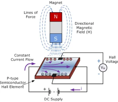
Hall effect sensor
A hall effect sensor (Figure 5.15) excels in its simplicity. The main working principle of the sensor is, as the name implies, the Hall effect, which basically makes it sense how strong the magnetic field around it is, to which its output voltage is directly proportional. The way it works can be seen more in-depth in Figure 5.16. There are two types of this sensor: threshold and linear. The threshold hall effect sensor acts as a switch as soon as a threshold in magnetic field is crossed, the linear hall effect sensor reacts linearly to a change in magnetic field around it. The linearity of the latter mentioned sensor makes it an excellent sensor for proximity sensing. Because Hall effect sensors can be completely analog, without any digital quantization or sampling required to use, they could theoretically be connected to an audio amplifier, with their output changing based on a vibration in the magnetic field within their range. In this project, a magnet could be attached to the rim of a porcelain plate with a hall effect sensor positioned above it (mounted on a separate, non-vibrating frame).
Figure 5.15: A linear Hall effect sensor.21
38
Figure 5.16: Diagram that shows how a Hall effect sensor works.22
The main downside of using this method, is that the output signal would be quite low depending on how much a porcelain plate would actually move when vibrating, and the fact that the placement of the sensor would have a huge impact on the characteristics of the sound, similar to what was mentioned previously about laser microphones. These characteristics may not make it the ideal candidate for audio purposes.
5.4.6
Contact microphone
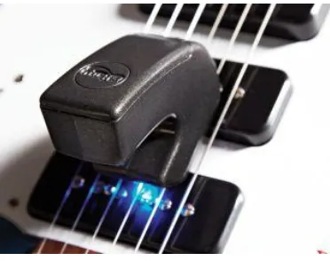
5.4.6.1 Piezo
To capture the sounds from any object with as much detail as possible, a contact microphone is often used, as stated before. This is a microphone that is attached directly to the surface that it aims to capture the sound characteristics of. One type of contact microphone is a piezoelectric microphone or piezo. This type of microphone is relatively cheap and often found in acoustic guitar pickups and clip-on guitar tuners. On acoustic guitars, they are usually mounted by means of an adhesive such as double-sided tape, 3M, Blu-Tack, hot glue, epoxy or dedicated Shadow Glue for transducers. Though these means are sufficient for picking up sounds, Blu-Tack, hot glue and Shadow Glue are still thick, shock absorbent materials that come between the piezo disc and the to-be sonified ceramic plate. This lack of direct contact between the contact microphone and the surface that it should pick up the sound from, combined with the shock absorbent properties of the adhesive results in a to some degree attenuated version of the sound that is sent to the amplifier.
As for clip-on tuners or other devices that clip onto an instrument for pitch detection or amplification purposes, such as the Snark tuner (Figure 5.17 &Figure 5.18), consist of a solid body, through which the vibrations produced by an instrument travel, to which a piezo disc is directly attached. Between the clip and the body of the instrument, small pieces of rubber are places. This is meant to both get a better grip on the instrument, as well as to prevent any scratching damage to the surface of the instrument. A side effect of this rubber is that certain higher frequency components of the sound produced by the instrument will be absorbed and not make it to the piezo disc. For amplification purposes, this would pose a problem, as it is impossible to send an accurate representation of the sound to the speaker. For tuning purposes however, it is actually a desirable phenomenon as this means less high-frequency harmonics and noise present in the signal have to be analyzed. The fundamental frequency and therefore the pitch of the sound
39
[image:40.612.74.229.112.264.2]will be more dominant to the tuner and thus easier to analyze and give visual feedback on using the display.
Figure 5.17: A Snark SN-8 clip-on tuner.23
Figure 5.18: The inside of a Snark clip-on tuner, with the location of the piezo disc clearly visible.24
Another way of mounting a contact microphone that came to mind during a brainstorm, is to use a magnet to keep the piezo in place and firmly pressed onto the surface that needs to be sonified. For example, a small magnet can be put on top of a piezo disc, which can then be put on the rim of a plate, which has a magnet underneath, causing the piezo disc to snap onto the rim of the plate because of the attraction between the magnets. As it turns out, this technique has actually been used before by sound artist Ed Devane. On the website for his company SoniPhorm, he sells a magnetic contact microphone (Figure 5.19), which he mentions being useful in scenarios where amplification of metal structures, such as gates or bridges or any other ferrous metal, is necessary [30]. The device has a 3D printed casing that has been filled with epoxy, a piezo disc and a strong magnet, which enables it to capture every last bit of detail as almost no damping occurs because of the lack of an absorbent material.
[image:40.612.72.290.294.505.2]
40
Figure 5.19: SoniPhorm magnetic contact microphone [40].
5.4.6.2 Accelerometer
[image:41.612.74.392.73.313.2]Aside from piezo-based contact microphones, there are others types of contact microphones as well. One example of this is the Omnia by Heartsound which uses an accelerometer (Figure 5.20). Its focus is on amplifying acoustic instrument sounds in as much detail as possible, but they claim it works on every vibrating surface [41][42]. It comes with its own dedicated pre-amplifier, which can be tweaked to the liking of the user regarding gain, frequency response and volume. The pre-amplifier features a BNC connector for the contact microphone input and an XLR connector for the sound output. As both of these are balanced and electronically shielded connections, there will be very little interference present in the final signal.
Figure 5.20: Dedicated Omnia pre-amplifier on the left, accelerometer-based contact microphone on the right [41].
![Figure 3.1: The design process of Creative Technology [30].](https://thumb-us.123doks.com/thumbv2/123dok_us/9652878.467288/22.612.86.411.214.679/figure-design-process-creative-technology.webp)
![Figure 5.10: Adafruit Large Surface Transducer frequency response graph [38].](https://thumb-us.123doks.com/thumbv2/123dok_us/9652878.467288/35.612.73.356.69.270/figure-adafruit-large-surface-transducer-frequency-response-graph.webp)