MASTER THESIS
MYOELECTRIC CONTROL
OF BIONIC HANDS VIA
MUSCULOSKELETAL
MODELLING,
ADMITTANCE CONTROL
AND FORCE FEEDBACK
Mikel Mateo
FACULTY OF ENGINEERING TECHNOLOGY DEPARTMENT OF BIOMECHANICAL ENGINEERING EXAMINATION COMMITTEE
dr.ir. M. Sartori dr.ir. A.Q.L. Keemink G.V. Durandau dr.ir. U. Yavuz
DOCUMENT NUMBER BW - 709
iii
Abstract
v
List of Acronyms
ADL Activities of Daily Living
BMI Brain-Machine Interface
CC Co-Contraction
DOF Degrees of Freedom
ECoG Electrocorticography
EEG Electroencephalography
EMG Electromyography
FRF Frequency Response Function
HOC Hand Open-Close
MCP Metacarpophalangeal
MMI Man-Machine Interface
MS Musculoskeletal
MTUs Musculotendon Units
MVC Maximal Voluntary Vontraction
MYO Myoelectric
NMS Neuromusculoskeletal
PR Pattern Recognition
sEMG Surface Electromyography
TMR Targeted Muscle Reinervation
vi
Contents
1 Background 1
1.1 Introduction . . . 1
1.2 Demographics and Prevalence . . . 1
1.3 Upper limb prostheses . . . 2
1.4 Myoelectric Control . . . 4
1.5 Challenges in Current Myoelectric Prosthesis . . . 7
1.6 Developments in Prosthetic Control . . . 8
1.7 Scope of Thesis: Towards bio-inspired grasp force control . . . 10
Bibliography 11 2 Paper 15 Appendices 16 A EMG-driven musculoskeletal model description, scaling and calibration 35 A.1 Model description . . . 35
A.2 Model Scaling . . . 35
A.3 EMG calibration . . . 36
A.4 Model calibration . . . 37
B System communication framework 45 B.1 Framework overview . . . 45
B.2 Michelangelo hand interface . . . 46
B.3 Processing in Matlab . . . 47
C Prosthesis Control In Matlab 51 C.1 Matlab GUI for prosthesis control: overview . . . 51
C.2 Description and steps for prosthesis control . . . 51
C.3 Friction parameters . . . 54
C.4 Admittance parameters . . . 54
D Admittance Model Equations 57 D.1 Friction model details . . . 57
D.2 Equations of Motion . . . 59
E Michelangelo hand’s force sensor calibration 61 E.1 Overview . . . 61
E.2 Calibration experiment . . . 61
F Prosthesis Dynamics Identification details 65 F.1 Identification experiment . . . 65
F.2 Computing the frequency response function . . . 66
F.3 Estimating the parameters of the FRF . . . 67
1
Chapter 1
Background
1.1
Introduction
Human hands are an essential tool to interact with the environment, explore, create, com-municate and socialise. They conform a highly versatile device capable of performing a large number of tasks using simple to fine and complex movements. They are an ex-tremely complex biomechanical system formed by twenty-seven bones and actuated by more than thirty muscles leading to more than 19 Degrees of Freedom (DOF). Further-more, thousands of sensors continuously measure physical variables, such as force and joint position, which are used as feedback to redefine our movements[1].
FIGURE 1.1: Upper limb amputation levels. Modified from [2]
However, traumatic accidents, dysvascular dis-eases (e.g. diabetes), cancer and congenital defi-ciencies, can lead to the loss of one or both upper limbs. This can have a life-changing impact in the amputee since the individual’s ability to perform activities of daily live (ADLs) autonomously, the capability to work and socialize are suddenly lim-ited [3].The levels of upper limb amputation can be classified as shown in Fig. 1.1.
Most patients suffering from an amputation re-quire the use of a prosthesis to restore arm function and recover the ability to perform tasks of daily liv-ing and increase quality of life. Preferably, pros-thesis should replace the function of the lost limb as close as possible, have a natural appearance, be lightweight and affordable. However, there exist an inevitable trade-off among such requirements as they are often hard to combine [4]. Taking those re-quirements as a base, this thesis is focused on im-proving the functionality of a prosthetic hand.
1.2
Demographics and Prevalence
2 Chapter 1. Background
limb amputations per 100.000. Among the upper limb amputees, 95% were unilateral and amputations were caused by trauma (85%), cancer (7%), infection (6%), dysvascular disease (1-2%), and drug overdose (0-1%) [7].
1.3
Upper limb prostheses
The first prostheses date back to ancient Egypt 3000 years ago, when they were both used for cosmetic and functional purposes. As medicine techniques and technology develop-ment advanced, doctors were able to prepare the limb stump for emerging prosthetic devices [8]. Today, different types of passive and active upper limb prosthesis exist to serve wide individual needs and preferences.
Passive upper limb prostheses
Passive prostheses are not equipped with any mechanical nor electrical part to provide active grasping capabilities. Passive prosthesis can be subdivided into cosmetic (Fig.1.2a) and functional (Fig.1.2b). Cosmetic prosthesis are mainly designed for aesthetic substitu-tion of the missing limb, while funcsubstitu-tional ones are designed to assist on specific activities by the use of a tool or hand. Passive functional prosthesis hands have an appearance close to the human hand and provide basic functionalities such as pushing and pulling. Passive functional tools have a mechanical appearance and are designed for activities requiring a special grasp type [1], [9].
(A) Cosmetic prothesis (B) Prosthetic tool
FIGURE1.2: Different examples of passive prosthesis
Body-powered prostheses
FIGURE1.3: Body powered prosthesis with
integrated cables and harnesses for mechani-cal control [10]
1.3. Upper limb prostheses 3
Externally powered prostheses
Externally powered prostheses are active prosthesis that exploit the power from an ex-ternal source to drive electrical or hydraulic actuators to move the prosthesis. They gen-erally offer greater control options and grasp force, at the expense of increased mainte-nance and weight due to built in batteries and electrical components. Nowadays, most commercially available advanced prostheses provide more than 1 DOF and allow for different grips and hand gestures to sequentially select the joints to be controlled. Exam-ples of commercially available prosthesis are Ottobock’s Michelangelo (Fig. 1.4a) , Touch Bionics’ i-Limb (Fig. 1.4b) and Bebionic hand (Fig. 1.4c). However, with more than 2 DOF the sequential control implies high mental effort and becomes non-intuitive, not natural, slow, difficult to learn and prone to errors [2], [12]. Therefore, to develop an intuitive and robust Man-Machine Interface (MMI) to control active prosthesis is a current challenge researchers are facing.
(A) Michelangelo hand (B) i-Limb hand (C) Bebionic hand
FIGURE1.4: Commercially available externally powered prosthesis
Man-Machine Interfaces
In prosthetics, there exist several types of MMIs that enable the control of the artificial limbs. More specifically, they depend and are classified based on the type of input ex-tracted from user’s intention. This can range from mechanical input (as explained in section 1.3), buttons, to Brain-Machine Interface (BMI) based on Electroencephalogra-phy (EEG) and ElectrocorticograElectroencephalogra-phy (ECoG) [13], [14]. However, the most widely used interface in market and research is myoelectric control (MYO), which makes use of sur-face electrodes (Sursur-face Electromyography (sEMG)) placed in the skin of the residual limb. This electrodes capture the muscle signals driven through the Peripheral or Cen-tral Nervous System (PNS and CNS) and derived from a voluntary muscle contraction which enables an amputee to control movements over multiple DOFs [1]. Moreover, re-searchers have also studied the use of intramusculuar EMG which provides access to deeper muscles and avoiding cross-talk and electrode shift. Although sEMG is preferred for its non-invasive nature and ease of use in daily live, intramuscular EMG seems a promising technique as wireless implantable recording devices are being developed [15], [16].
4 Chapter 1. Background
close the real hand, which triggers the artificial hand to close. This technique allows for more intuitive control over multiple DOFs [13], [14], [17].
FIGURE1.5: Targeted muscle reinnervation surgical procedure
1.4
Myoelectric Control
EMG Processing
EMG signal amplitude is usually below 10mV and its frequency content goes from 0 to 500 Hz, which makes it sensitive to noise and artefacts. For this reason, EMG is low and high pass filtered to exclude frequency content outside its common range. Further filtering is made depending on the application of interest and notch filters are applied to remove power line artefacts.
Additionally, EMG signals need to be analysed in real-time. This is made by using time segments called windows, where multiple samples are recorded and their ampli-tude is averaged. The ampliampli-tude of the EMG signal is calculated, for each electrode, by using the root-means-square value (RMS=
q 1
n∑ni=1EMG2i) or the mean-absolute value
(MAV = n1∑ni=1EMG2i
) for a givennnumber of samples in each window [18]. There are different windowing techniques, such as adjacent windowing and overlapping tech-niques, where part of the previous window is used to compute a new average. The use of windowing, windowing technique and length depends on the control framework or algorithm used, as computing the average of such windows adds computation time [19]. Following this process, user’s intentions are deciphered and communicated to the motor controller in order to actuate the appropriate DOF. A range of different methods exist to translate information obtained from EMG signals to control commands. These are usually classified either as sequential or simultaneous. Sequential control actuates only 1 DOF at a time, while simultaneous control allows to actuate more than 1 DOF. Although sequential control is most used, research is focusing on simultaneous control of more than one DOF. In the following lines, current MYO control methods are presented.
Control Strategies
On-off control
1.4. Myoelectric Control 5
actuation is independent of the muscle contraction level. This control strategy can be implemented using a pair of antagonist muscles or only one muscle, where two different contraction levels actuate two different directions [16], [17].
Proportional control
[image:11.595.88.512.404.569.2]The human neuromotor control system can vary joint torques, velocities and positions at will and therefore, the ’on-off’ prosthetic control was non-intuitive for humans. Hence, proportional control was developed. In such control scheme the velocity command given to the motors is proportional to the muscle contraction level. Moreover, contraction could not only be proportionally mapped to velocity, but also to other mechanical quantities such as force or position. Therefore, force control can be used to proportionally vary the grasp force, although this remains non-intuitive. Furthermore, position control can be used to proportionally prescribe position commands to the prosthesis. However, given the stochastic nature of the EMG signal, it would be difficult to reach specific position and even more, the amputee should maintain a constant contraction level to stay in one position which would cause fatigue. Hence, velocity control is preferred over force and position control as it provides smoother control and is less fatiguing for the user, as it is not needed to keep muscle contraction for the prosthesis to stay in a specific configura-tion. However, proportional control can be useful for gross prosthetic movements but not for finer control [16], [17], [20].
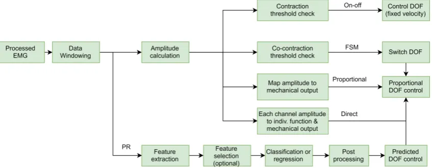
Fig. 1.6 provides an overview of the steps involved in each control method, where it can be seen that other control schemes are used along with proportional control.
FIGURE 1.6: Scheme representing different MYO control methods. For on-off control a fixed velocity is used. In proportional control a mechanical output (force, velocity, position) can be used to drive the prosthesis. If multiple and cross-talk free control sites are available, direct control can be used to drive the prosthesis in a proportional way assigning one function to each of the control sites. In FSM two control sites can be used to select the desired DOF by co-contraction. In PR, features are extracted and used as input for a classifier or a regression analysis, where the output is the predicted, desired DOF.
Direct control
6 Chapter 1. Background
[17]. However, this can be overcome by the use of intramuscular EMG, although individ-ual control of each muscle is challenging for the amputees [21].
Finite state machine
Finite state machine (FSM) appears as an alternative to control prosthesis with more than one DOF when the number of EMG signals is limited, as in pure proportional and di-rect control. This method consist on switching the DOF to actuate by using different methods. Co-contraction (CC) is regularly used to switch between DOFs. This switch-ing method consists on co-contractswitch-ing two antagonistic muscles and, when a predefined amplitude threshold is passed, the DOF to actuate is changed (Fig. 1.7). Afterwards, the selected DOF is controlled proportionally [17]. This type of control means a non-intuitive, slow transfer of the user’s intentions to the prosthesis and requires long training periods and high-mental effort [12]. However, proportional FSM remains as the default control method in commercially available prosthesis and is often used as the golden standard for comparison with new control methods [2].
FIGURE1.7: Co-contraction based FSM
Pattern Recognition
In order to overcome the limitations previously cited, the research community came up with techniques based on Pattern Recognition (PR). The core of PR consists on recogniz-ing patterns in data that will be used topredict the output for new data instances. In MYO control, PR algorithms can be trained to recognize the patterns of muscle activation obtained from EMG signals to derive the motor intention (see Fig. 1.6). On this process, data is windowed and multiple features from time, frequency and time-frequency do-main are extracted and used as input for the learning algorithm. A higher number of features can result in greater computational complexity and feature selection techniques are often implemented as an additional step to remove irrelevant features.
In this point, features can be classified or used as input for regression methods. In the first case, a classification algorithm is used, such as artifical neural networks (ANN) or linear discriminant analysis (LDA) and a class label (or DOF label in MYO control) is predicted [16]. However, classification can only predict one prosthetic function at a time. To solve this problem, multiple-class algorithms have been developed, although this increases the number of patterns to be trained which can be cumbersome [17], [22]. Furthermore, classification does not support proportional control of the prosthesis and this needs to be computed in parallel, which adds more complexity to the control algo-rithm.
1.5. Challenges in Current Myoelectric Prosthesis 7
are mapped to output continuous value by using a selected function. Therefore, there is no need of computing proportional control in parallel. This allows for the possibility of simultaneous control of more than 1 DOF.
As a last stage, with the aim of removing wrongly predicted instances, post-processing techniques such as majority voting (MV) are used, where certain number of past predic-tion samples are used to see which one was predicted the most.
1.5
Challenges in Current Myoelectric Prosthesis
The earliest PR-EMG based prostheses date back to 1950s and 1960s and since then many PR based EMG controlled prosthesis studies, offline and online, have been carried out by the showing acceptable level of classification accuracy (>90%) and functionality [18], [23]. However, a study on the prosthesis use carried out in 1995 stated that only the 18% of amputees wears a MYO prosthesis [24], and more interestingly, that the 27% of amputees fitted with an active body-powered or MYO prosthesis use their prosthesis in a passive way. Moreover, a more recent study from 2007 reported that the overall prosthesis rejection rate was found to be as much as 23%, despite the great technological advancements achieved by the research community in the laboratory [11]. The main cause of such rejection for advanced prosthesis is due to the fact that the control interface they provide does not allow for natural control. Human movement implies simultaneous coordination and proportional movement of multiple DOFs across several joints at the same time while applying the right amount of force when handling objects or interacting in any other way with the world.
In this sense, PR-algorithms attempt to solve the challenging problem of modelling human biomechanics by encapsulating all neuromuscular variables (e.g. EMG, joint an-gles and torques) in a non-linear function. This way, the dynamics of the NMS system are reduced to a black box where the relationship of its variables is not explicitly mod-elled, which does not allow direct understanding of the transformation mechanics be-tween variables [25]. It is because of this reason that new control strategies for prosthetic hands based on modelling the underlying biomechanics of human movement are being explored. Modelling true biomechanics would allow for more intuitive control, without the learning burden machine learning methods involve.
8 Chapter 1. Background
FIGURE1.8: Example of haptic feedback. A vibrotactile stimulation unit informs the user about prosthesis states and forces [27].
Such type of feedback is also calledhapticfeedback. Nevertheless, the impact these techniques have in grasp force accuracy is still unclear. On the other hand, other re-searchers attempted to improve grasp force control by feeding back the forces exerted in the prosthetic hand to the prosthetic controller to update control commands. How-ever, the techniques used are based on commanding small force or position increments or decrements to find a suitable grasping force, which neither provide an optimal nor natural way to control interaction forces (refer to Chapter 2, section I-B for an extended review on the mentioned techniques).
In conclusion, research is focused on creating new control strategies that resemble the way humans produce movement and interact with the world. This master thesis aims to provide a proof-of-concept control strategy that allows for intuitive control of the prosthetic hand’s DOF’s and grasp force control.
1.6
Developments in Prosthetic Control
Model Based Control
Unlike in pattern recognition, building computational models of the NMS system allows to extract parameters that cannot be measured experimentally. This is useful to gain in-sight on how the internal variables of the NMS change on time, like muscle length and forces. This way, subject-specific NMS can be created and used to plan rehabilitation or design rehabilitation robotics, simulate neuromuscular disorders and analyse motor control [25], [28]. In the scheme of upper limb prosthesis, EMG can provide an exper-imental interface to extract neural information of an individual’s intended movement and estimate the biomechanics of an amputated limb, such as forces and torques, which are transformed and used to control the prosthetic hand. This control scheme is called
EMG-driven musculoskeletal modellingbased control. Recently, Sartori et al. [29] demon-strated the use of EMG-driven musculoskeletal modelling to control a prosthetic hand. Such control scheme showed truly intuitive, human-like prosthetic control over multiple DOFs simultaneously. Because of these reasons, this master thesis is based on the work of Sartori et al.
1.6. Developments in Prosthetic Control 9
is performed for muscle parameter values that vary non-linearly across subjects [30]. Ul-timately, the predicted joint torques (herewith also referred as moments) can be trans-formed and used as input for the controlled device. A more detailed explanation of the NMS model’s complete pipeline can be found in chapter 2, section II-B.
FIGURE1.9: General NMS modelling pipeline. Modified from [25].
Admittance control: interacting with the environment
In section 1.5, the problem of fine grasp force control in current MYO prosthesis was introduced. Along with this, the efforts of the research community to restore amputees’ ability for a better force control were introduced. Here, some researchers tried to control the forceorthe motion of the hand to increase or decrease the interaction force between the prosthetic and an object, for example. Instead of controlling either force or motion, an idea could be to control both variables at once to see what effect causes one on the other: any applied force to an object will cause some degree of deformation on the object and the object will counteract this deformation with a reaction force in opposite direction. Therefore, the key for a safe interaction is tomodel the relationship between the forces and the motioncaused by this forces, rather than each of the two variables alone. Thedynamic relationbetween force and motion is calledmechanical admittance. To illustrate this concept an example is provided in the following lines.
FIGURE1.10: Illustration of the concept of admittance.
10 Chapter 1. Background
In admittance control, a virtual model of the dynamics with which wewishthe con-trolled robotic device to move is designed. Therefore, such dynamics can also be called
desireddynamics. This master thesis makes use of the paradigm of admittance control to model the grasp dynamics while accounting for external forces arisen from the interac-tion with the environment (refer to A, secinterac-tion II-D).
1.7
Scope of Thesis: Towards bio-inspired grasp force control
11
Bibliography
[1] D. Farina, W. Jensen, and M. Akay, Eds.,Introduction to neural engineering for mo-tor rehabilitation, Hoboken, N.J: John Wiley & Sons, 2013, 579 pp., ISBN: 978-0-470-91673-5.
[2] F. Cordella, A. L. Ciancio, R. Sacchetti, A. Davalli, A. G. Cutti, E. Guglielmelli, and L. Zollo, “Literature review on needs of upper limb prosthesis users”,Frontiers in Neuroscience, vol. 10, May 12, 2016,ISSN: 1662-453X. DOI:10 . 3389 / fnins . 2016 . 00209. [Online]. Available:http://journal.frontiersin.org/Article/10.3389/ fnins.2016.00209/abstract(visited on 09/20/2019).
[3] K. Demet, N. Martinet, F. Guillemin, J. Paysant, and J.-M. André, “Health related quality of life and related factors in 539 persons with amputation of upper and lower limb”,Disability and Rehabilitation, vol. 25, no. 9, pp. 480–486, Jan. 2003,ISSN: 0963-8288, 1464-5165. DOI: 10 . 1080 / 0963828031000090434. [Online]. Available:
http://www.tandfonline.com/doi/full/10.1080/0963828031000090434(visited on 09/20/2019).
[4] E. Biddiss, “Need-directed design of prostheses and enabling resources”, in Am-putation, Prosthesis Use, and Phantom Limb Pain, C. Murray, Ed., New York, NY: Springer New York, 2009, pp. 7–21,ISBN: 978-0-387-87461-6 978-0-387-87462-3.DOI:
10.1007/978-0-387-87462-3_2. [Online]. Available:http://link.springer.com/ 10.1007/978-0-387-87462-3_2(visited on 09/22/2019).
[5] K. Ziegler-Graham, E. J. MacKenzie, P. L. Ephraim, T. G. Travison, and R. Brook-meyer, “Estimating the prevalence of limb loss in the united states: 2005 to 2050”,
Archives of Physical Medicine and Rehabilitation, vol. 89, no. 3, pp. 422–429, Mar. 2008, ISSN: 00039993. DOI:10.1016/j.apmr.2007.11.005. [Online]. Available:https: / / linkinghub . elsevier . com / retrieve / pii / S0003999307017480 (visited on 09/22/2019).
[6] S. Wild, G. Roglic, A. Green, R. Sicree, and H. King, “Global prevalence of diabetes: Estimates for the year 2000 and projections for 2030”,Diabetes Care, vol. 27, no. 5, pp. 1047–1053, May 1, 2004,ISSN: 0149-5992, 1935-5548.DOI:10.2337/diacare.27. 5.1047. [Online]. Available:http://care.diabetesjournals.org/cgi/doi/10. 2337/diacare.27.5.1047(visited on 09/22/2019).
[7] K. Østlie, O. H. Skjeldal, B. Garfelt, and P. Magnus, “Adult acquired major up-per limb amputation in norway: Prevalence, demographic features and amputation specific features. a population-based survey”, Disability and Rehabilitation, vol. 33, no. 17, pp. 1636–1649, Jan. 2011,ISSN: 0963-8288, 1464-5165.DOI:10.3109/09638288. 2010.541973. [Online]. Available:http://www.tandfonline.com/doi/full/10. 3109/09638288.2010.541973(visited on 09/22/2019).
12 Bibliography
[9] B. Maat, G. Smit, D. Plettenburg, and P. Breedveld, “Passive prosthetic hands and tools: A literature review”,Prosthetics and Orthotics International, vol. 42, no. 1, pp. 66– 74, Feb. 2018, ISSN: 0309-3646, 1746-1553. DOI: 10 . 1177 / 0309364617691622. [On-line]. Available:http://journals.sagepub.com/doi/10.1177/0309364617691622
(visited on 09/25/2019).
[10] M. Klerstad and M. Svensson, “Creating a body powered prosthetic arm with 3d printing technology”, p. 75,
[11] E. A. Biddiss and T. T. Chau, “Upper limb prosthesis use and abandonment: A sur-vey of the last 25 years”,Prosthetics and Orthotics International, vol. 31, no. 3, pp. 236– 257, Sep. 2007,ISSN: 0309-3646, 1746-1553.DOI:10.1080/03093640600994581. [On-line]. Available:http://journals.sagepub.com/doi/10.1080/03093640600994581
(visited on 09/22/2019).
[12] C. Castellini, P. Artemiadis, M. Wininger, A. Ajoudani, M. Alimusaj, A. Bicchi, B. Caputo, W. Craelius, S. Dosen, K. Englehart, D. Farina, A. Gijsberts, S. B. Godfrey, L. Hargrove, M. Ison, T. Kuiken, M. Marković, P. M. Pilarski, R. Rupp, and E. Scheme, “Proceedings of the first workshop on peripheral machine interfaces: Go-ing beyond traditional surface electromyography”,Frontiers in Neurorobotics, vol. 8, Aug. 15, 2014,ISSN: 1662-5218.DOI:10.3389/fnbot.2014.00022. [Online]. Avail-able:http://journal.frontiersin.org/article/10.3389/fnbot.2014.00022/ abstract(visited on 09/25/2019).
[13] J. Ribeiro, F. Mota, T. Cavalcante, I. Nogueira, V. Gondim, V. Albuquerque, and A. Alexandria, “Analysis of man-machine interfaces in upper-limb prosthesis: A review”,Robotics, vol. 8, no. 1, p. 16, Feb. 21, 2019,ISSN: 2218-6581.DOI:10.3390/ robotics8010016. [Online]. Available:http://www.mdpi.com/2218-6581/8/1/16
(visited on 09/26/2019).
[14] A. E. Schultz and T. A. Kuiken, “Neural interfaces for control of upper limb pros-theses: The state of the art and future possibilities”,PM&R, vol. 3, no. 1, pp. 55–67, Jan. 2011,ISSN: 19341482.DOI:10.1016/j.pmrj.2010.06.016. [Online]. Available:
http://doi.wiley.com/10.1016/j.pmrj.2010.06.016(visited on 09/26/2019). [15] L. H. Smith and L. J. Hargrove, “Comparison of surface and intramuscular EMG
pattern recognition for simultaneous wrist/hand motion classification”, in 2013 35th Annual International Conference of the IEEE Engineering in Medicine and Biology Society (EMBC), Jul. 2013, pp. 4223–4226.DOI:10.1109/EMBC.2013.6610477. [16] P. Geethanjali, “Myoelectric control of prosthetic hands: State-of-the-art review”,
Medical Devices: Evidence and Research, vol. Volume 9, pp. 247–255, Jul. 2016,ISSN: 1179-1470.DOI:10.2147/MDER.S91102. [Online]. Available:https://www.dovepress. com/myoelectric-control-of-prosthetic-hands-state-of-the-art-review-peer-reviewed-article-MDER(visited on 09/26/2019).
[17] A. D. Roche, H. Rehbaum, D. Farina, and O. C. Aszmann, “Prosthetic myoelec-tric control strategies: A clinical perspective”,Current Surgery Reports, vol. 2, no. 3, p. 44, Mar. 2014, ISSN: 2167-4817. DOI: 10 . 1007 / s40137 - 013 - 0044 - 8. [Online]. Available:http://link.springer.com/10.1007/s40137-013-0044-8(visited on 09/26/2019).
[18] E. Scheme and K. Englehart, “Electromyogram pattern recognition for control of powered upper-limb prostheses: State of the art and challenges for clinical use”,
Bibliography 13
//www.rehab.research.va.gov/jour/11/486/pdf/scheme486.pdf(visited on 10/02/2019).
[19] M. Hakonen, H. Piitulainen, and A. Visala, “Current state of digital signal process-ing in myoelectric interfaces and related applications”,Biomedical Signal Processing and Control, vol. 18, pp. 334–359, Apr. 2015,ISSN: 17468094.DOI:10.1016/j.bspc. 2015.02.009. [Online]. Available:https://linkinghub.elsevier.com/retrieve/ pii/S174680941500021X(visited on 10/01/2019).
[20] A. Fougner, O. Stavdahl, P. J. Kyberd, Y. G. Losier, and P. A. Parker, “Control of upper limb prostheses: Terminology and proportional myoelectric control—a re-view”, IEEE Transactions on Neural Systems and Rehabilitation Engineering, vol. 20, no. 5, pp. 663–677, Sep. 2012, ISSN: 1534-4320, 1558-0210. DOI: 10 . 1109 / TNSRE . 2012 . 2196711. [Online]. Available: http : / / ieeexplore . ieee . org / document / 6205630/(visited on 09/30/2019).
[21] L. H. Smith, T. A. Kuiken, and L. J. Hargrove, “Real-time simultaneous and propor-tional myoelectric control using intramuscular EMG”,Journal of Neural Engineering, vol. 11, no. 6, p. 066 013, Dec. 1, 2014, ISSN: 1741-2560, 1741-2552. DOI:10 . 1088 / 1741 - 2560 / 11 / 6 / 066013. [Online]. Available: http : / / stacks . iop . org / 1741 -2552 / 11 / i = 6 / a = 066013 ? key = crossref . edc34b0f5a0b7a836ef83b5d18d6ba47
(visited on 09/30/2019).
[22] A. J. Young, L. H. Smith, E. J. Rouse, and L. J. Hargrove, “Classification of simul-taneous movements using surface EMG pattern recognition”,IEEE Transactions on Biomedical Engineering, vol. 60, no. 5, pp. 1250–1258, May 2013.DOI:10.1109/TBME. 2012.2232293.
[23] N. Jiang, S. Dosen, K. Muller, and D. Farina, “Myoelectric control of artificial limbs #8212;is there a need to change focus? [in the spotlight]”, IEEE Signal Processing Magazine, vol. 29, no. 5, pp. 152–150, Sep. 2012.DOI:10.1109/MSP.2012.2203480. [24] T. W. Wright, A. D. Hagen, and M. B. Wood, “Prosthetic usage in major upper
extremity amputations”,The Journal of Hand Surgery, vol. 20, no. 4, pp. 619–622, Jul. 1995,ISSN: 03635023.DOI:10.1016/S0363-5023(05)80278-3. [Online]. Available:
https://linkinghub.elsevier.com/retrieve/pii/S0363502305802783(visited on 10/03/2019).
[25] M. Sartori, D. G. Llyod, and D. Farina, “Neural data-driven musculoskeletal model-ing for personalized neurorehabilitation technologies”,IEEE Transactions on Biomed-ical Engineering, vol. 63, no. 5, pp. 879–893, May 2016, ISSN: 0018-9294, 1558-2531. DOI: 10 . 1109 / TBME . 2016 . 2538296. [Online]. Available: https : / / ieeexplore . ieee.org/document/7440844/(visited on 10/03/2019).
[26] C. Antfolk, M. D’Alonzo, B. Rosén, G. Lundborg, F. Sebelius, and C. Cipriani, “Sen-sory feedback in upper limb prosthetics”,Expert Review of Medical Devices, vol. 10, no. 1, pp. 45–54, Jan. 2013, ISSN: 1743-4440, 1745-2422. DOI:10.1586/erd.12.68. [Online]. Available:http://www.tandfonline.com/doi/full/10.1586/erd.12.68
(visited on 03/01/2019).
14 Bibliography
[28] F. Valero-Cuevas, H. Hoffmann, M. Kurse, J. Kutch, and E. Theodorou, “Computa-tional models for neuromuscular function”,IEEE Reviews in Biomedical Engineering, vol. 2, pp. 110–135, 2009, ISSN: 1937-3333, 1941-1189. DOI: 10 . 1109 / RBME . 2009 . 2034981. [Online]. Available:http://ieeexplore.ieee.org/document/5342785/
(visited on 10/15/2019).
[29] M. Sartori, G. Durandau, S. Došen, and D. Farina, “Robust simultaneous myo-electric control of multiple degrees of freedom in wrist-hand prostheses by real-time neuromusculoskeletal modeling”,Journal of Neural Engineering, vol. 15, no. 6, p. 066 026, Dec. 1, 2018, ISSN: 1741-2560, 1741-2552. DOI: 10 . 1088 / 1741 - 2552 / aae26b. [Online]. Available: http : / / stacks . iop . org / 1741 - 2552 / 15 / i = 6 / a = 066026?key=crossref.24203caa63d0aa7e7a24cbd38ab35e99(visited on 02/21/2019). [30] M. Sartori, M. Reggiani, D. Farina, and D. G. Lloyd, “EMG-driven forward-dynamic
estimation of muscle force and joint moment about multiple degrees of freedom in the human lower extremity”, PLoS ONE, vol. 7, no. 12, P. L. Gribble, Ed., e52618, Dec. 26, 2012, ISSN: 1932-6203. DOI: 10 . 1371 / journal . pone . 0052618. [Online]. Available: http : / / dx . plos . org / 10 . 1371 / journal . pone . 0052618 (visited on 10/15/2019).
[31] C. Pizzolato, D. G. Lloyd, M. Sartori, E. Ceseracciu, B. J. Fregly, and M. Reggiani, “CEINMS: A toolbox to investigate the influence of different neural control solu-tions on the prediction of muscle excitation and joint moments during dynamic motor tasks”, p. 23, 2016.
[32] R. Pintelon and J. Schoukens,System identification: a frequency domain approach. John Wiley & Sons, 2012.
[33] A. Q. Keemink, H. van der Kooij, and A. H. Stienen, “Admittance control for phys-ical human–robot interaction”,The International Journal of Robotics Research, vol. 37,
no. 11, pp. 1421–1444, Sep. 2018,ISSN: 0278-3649, 1741-3176.DOI:10.1177/0278364918768950. [Online]. Available:http://journals.sagepub.com/doi/10.1177/0278364918768950
(visited on 02/21/2019).
15
Chapter 2
17
Myoelectric control of bionic hands via
musculoskeletal modelling, admittance control and
force feedback
Mikel Mateo, BSc, Massimo Sartori,Member, IEEE, Arvid QL Keemink, Guillaume Durandau, Student Member, IEEE
Abstract—Current myoelectric upper limb prostheses do not provide truly bio-mimetic control that allows for both intuitive control and reliable grasp dynamics. This is mainly because current machine learning approaches provide a control interface that is non-intuitive and extraordinarily different from human natural control. Furthermore, the lack of afferent feedback pathways forces the amputee to rely mainly on visual feedback to control grasp action, where the implementation of state-of-the-art haptic feedback techniques does not show conclusive results on the help of grasp force control. In this work, a subject-specific EMG-driven musculoskeletal model coupled to an admittance controller is used to drive a bionic hand. The admittance model virtually mimics the grasp dynamics of a real hand interacting with the environment. This way, the prosthetic hand (Michelangelo hand, Ottobock) can readjust its control commands during interaction by accounting for external forces. Theoretical stability boundaries of the control system are analysed for stable interaction and experimental tests are carried out comparing the proposed control framework to non-admittance based EMG-driven musculoskeletal modelling during grasping tasks. Experimental outcomes show positive results when compared to non-admittance based control. This control framework sets the bases to enable safer prosthesis-environment interaction without the need of constant visual feedback.
Index Terms—admittance model, control system stability, EMG-driven musculoskeletal modelling, myoelectric control, sys-tem identification.
I. INTRODUCTION
T
HE loss of an upper limb can have a profound impact in the quality of life, since the individual’s ability to perform activities of daily live (ADLs) autonomously, the capability to work and socialize are suddenly limited [1]. Myoelectric prosthesis (MYO) aim to restore the missing functions by providing a man-machine interface based on electromyography (EMG) which enables the amputee to control the artificial limb. Surface electrodes placed in an antagonistic muscle pair in the residual limb capture the muscle signals driven through the neuromotor system, after which they are processed and used as input to control prosthetic joints. Nowadays, most commercially available advanced prostheses provide control of more than one degree of freedom (DOF) and allow for different grips and hand gestures by the co-contraction of two muscles to sequentially select the different joints to be controlled. Examples of commercially available prosthesis are Ottobocks Michelangelo, Touch Bionics i-Limb and Bebionic. However, with more than 2 DOF the sequential control implies high mental effort and becomes non-intuitive, not natural,slow, difficult to learn and prone to errors [2], [3]. Moreover, the lack of proprioceptive feedback forces the user to rely primarily on visual information, which leads to excessive or poor grasp forces [4]. Therefore, despite the great technolog-ical advancements, studies stated that the overall prosthesis rejection rate was found to be as much as 23% [5].
The principal problem of MYO-controlled prosthesis is that it is extraordinarily different from human natural control, which requires simultaneous coordination and proportional movement of multiple DOFs across several joints at the same time, while applying the right amount of force when handling fragile objects or interacting with humans and animals [6].
The ultimate goal of upper limb prosthetics is to replicate the human control strategy to provide truly bio-mimetic con-trol that allows for safe grasp dynamics. However, several challenges arise in this path given the state of current MYO-prosthesis.
A. Challenges in Current Myoelectric Prosthesis
Approaches based on machine learning algorithms, like pattern recognition (PR) and regression techniques, have been employed for prosthetic control to resolve the complexity of mimicking human-like control. As such, these techniques do not capture the underlying biomechanics of the human neuromusculoskeletal system (NMS) and they rather reduce the relation between neuro-biomechanical variables to a black box. Moreover, the same movement can be produced by different muscle recruitment strategies due to a redundant number of muscle tendon units (MTUs) controlling a limited number of DOFs. PR-algorithms are sensitive to this fact due to specific training conditions which fail to generalize to new, untrained conditions [6]. Ultimately, they fail to create a bio-mimetic prosthetic interface.
18
account for this fact, haptic feedback techniques are being developed to recover lost proprioception and exteroception where the amputee is fitted with a feedback unit, such as a vibrotactile cuff. However, although haptic feedback is able to characterize, for example, grip force intensity, it cannot transmit if applied forces are insufficient or excessive and therefore is not able to guide amputees response[9]. In this scenario, the results regarding the benefits of haptic feedback for grasp force control in the literature are inconclusive and contradictory [10].
In conclusion, the existing gap between the intent of the user, control strategy and reliable interaction with the environ-ment lies in the absence of a bio-inspired model that captures their relationship. This is, there is currently no human-like prosthetic control strategy which allows for an intuitive control and which automatically readjusts its control commands when excessive grasping forces are achieved through the derived intent of the amputee. Therefore, this work is focused on building a control strategy that a) allows for an intuitive control by EMG-driven musculoskeletal (MS) modelling, and b) captures thedynamic relationbetween the predicted forces by such model, phantom limb dynamics and contact forces arising from grasping real objects. As feedback pathways to the user are still an inconclusive research topic, they are left as a future development to complement and complete the proposed human-like control strategy.
B. Towards bio-mimetic control
Unlike machine learning methods, EMG-driven muscu-loskeletal (MS) modelling provides truly intuitive and robust MYO control over multiple DOFs simultaneously by estimat-ing phantom limb biomechanics out of the EMG signals. In EMG-driven MS modelling, a subject-specific model of the individuals anthropometry is used to estimate net torque over multiple DOFs. Forces and torques produced by individual MTUs are estimated out of their kinematics (length, velocity and moment-arm) and from EMG extracted neural excitations. The MS model is calibrated in a closed loop formulation for anatomical and physiological internal parameters that vary nonlinearly across individuals [11], [12]. In short, MS decodes motor intentions and transforms them into joint torques by taking into account subject’s limb kinematics and dynamics.
In the scheme of upper limb prosthesis, Sartori et al. [13] developed a subject-specific, real-time simultaneous multi-joint prosthetic control using an EMG-driven MS model. In that work, the predicted joint torques where directly mapped to joint velocity which was used as input for the control of an upper limb prosthesis. Hence, the prosthetic device was used as a physical integrator into device position, thus eliminating the need of numerical integration of velocity into position. However, the direct mapping from joint torque to joint velocity does not take into account limb dynamics and possible displacements caused by external forces acting on the prosthetic hand. That is, the prosthesis still cannot react to the environment by readjusting its commands when is in contact with an object. Therefore, the dynamic relation between predicted joint torque, external forces and output
motion needs to be modelled to achieve truly bio-mimetic control that allows for robust interaction with real objects.
Several studies attempted to integrate external forces in prosthetic control with approaches based on hybrid force-position control with sliding-mode control [14] and object stiffness estimation [15], parallel force-position control [16], artificial neural network (ANN) models to estimate new com-mands from net external forces [17] and normal to shear force ratio based rules [18], where in many of them the velocity/position/force input signal of the artificial hand is increased until a predefined interaction force threshold is reached. However, none of them established a dynamic relation between input and output (velocity/force) but rather controlled them separately. Moreover, the mentioned approaches highly depend on the kind of prosthesis used (e.g. actuation mechan-ics, sensors available etc.) which does not help to create a generic solution for this problem.
In this sense, the limb dynamics that convert net torques to motion can be regarded as a mechanical admittance. The concept of admittance can be explained as the amount of motion the limb ’admits’ for an input torque. Then, admittance
controls the relation between torque and motion. Admittance control is the inverse of the impedance control paradigm proposed in the works by Hogan [19] and Colgate et al. [20] and which allows to control both motion and force at once. This prevents from controlling each variable separately by modelling their relation, unlike the techniques described above. More explicitly, in admittance control, the relation between force and motion is modelled through a virtual model of the dynamics of the physical system. This virtual model can be considered as the desired dynamics the controlled device is aimed to follow. Admittance control-based approaches have previously been used in bio-robotics for exoskeleton control, rehabilitation purposes and movement support to enable the controlled device to respond with desired dynamics [21], [22].
19
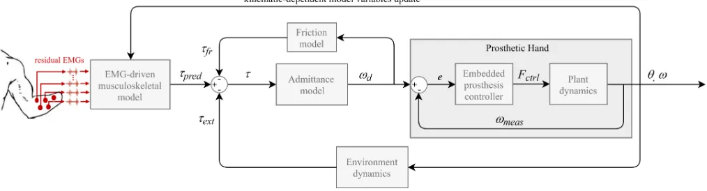
Fig. 1. Proposed control framework composed of the EMG-driven MS model, the admittance model coupled with a joint friction model and the prosthetic hand itself. The EMG-driven MS-model predicts joint torquesτpred based on EMG-derived neural activations generated by subject’s intended movement.
The admittance model represent the dynamics of the open/close of the hand while interacting with environment, which produces a reaction torqueτext.
The friction model reproduces the biological friction conditions in which joints move and produces a friction torqueτf r. This admittance model coupled to
the friction model transforms the net torqueτinto desired angular velocity referencesωd. The desired velocity is used as reference for the prosthetic hand
controller. The erroreis the difference between measured velocityωmeasandωd. The hand controller attempts to drive the prosthetic device by applying a
control forceFctrl. The output kinematics areωmeasand prosthesis angular positionθ.
II. MATERIALS ANDMETHODS
The control framework presented in this paper is an ex-tension of the work of Sartori et al. [13]. The focus of this paper is toimprovethe grasping force dynamics by accounting for external forces. This is done through an admittance model, coupled with a joint friction model, which reproduces, to some extent, the desired dynamics of a real hand interacting with the external world. The proposed control strategy is depicted in Fig. 1 and comprises of three major components including: the EMG-driven MS model, the admittance model coupled with a joint friction model and the prosthetic hand. The framework allows for simultaneous control of 2 DOFs: hand opening-closing (HOC) and wrist pronation-supination (WPS). However, because this paper focuses on grasp dynamics, only HOC was used for our experiments to test the implemented admittance model (see section IV for further explanation).
The experimental procedures were performed by three healthy subjects on two consecutive sessions. First, a generic MS model was scaled and calibrated for each subject’s anthropometry and force-generating capacity. In the second session, the subject-specific model was used to perform the experimental tasks.
In the following lines, we first describe how anthropometry data were collected for establishing subject-specific MS model (see section II-A). Secondly, we describe the components of our proposed control strategy (sections II-B to II-D) and explain the processes to find the theoretical stability bound-aries of the prosthesis-environment interaction (section II-G). Thirdly, the online prosthesis control experimental procedures are described (see section II-H).
A. Data recording and processing
A generic dynamic upper limb model was scaled on Open-Sim for each subject. For this, the anatomical position of the shoulder joint, elbow, wrist, metacarpophalangeal (MCP) joint of the middle finger and index finger length were taken for each subject. Scaling of the MS model was therefore done
using manual scale factors for each participant instead of using motion capture data for the ease of the subjects. Anatomical measures were taken in natural position, with no elbow flexion, such that the position of the arm matched the pose of the generic OpenSim model. Although the generic MS model provides all DOFs and MTUs in the human hand [23], only a subset of these were employed.
All experimental procedures were performed using a pow-ered multi-functional Michelangelo prosthetic hand (Ottobock HealthCare GmbH, Duderstadt, DE) equipped with WPS and HOC motors and passive flexion-extension (WFE). The hand can produce lateral grasp and palmar grasp, where only palmar grasp (HOC) was used for our experiments.
EMG was recorded using 8 EMG Ottocbock electrodes connected to the central control unit of the prosthesis (Ax-onMaster 13E500, Ottobock). EMG electrodes consisted of an on-board 90-450 Hz bandpass filter and 50Hz notch filter [24]. Electrodes were placed in eight upper limb muscle groups including: biceps brachii, pronator teres, extensor carpi radialis, extensor carpi ulnaris, extensor digitorum, flexor carpi radialis, flexor carpi ulnaris and flexor digitorum [13]. The subjects were asked to perform a set of movements for EMG normalization including: wrist flexion, extension, pronation, supination, ulnar deviation, radial deviation, hand open and close and rest (no movement). EMG values for each channel were normalized by the highest processed value during the movement phases and removed base line by the mean value during no movement.
20
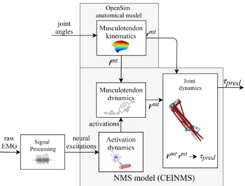
Fig. 2. Schematic structure of EMG-driven MS model. Neural excitations are obtained from raw EMG signals as linear envelopes and transferred into muscle activations. MTU lengths (lmt) and moment arms (rmt) are obtained
from the input joint angles using multi-dimensional cubic B-splines. MTU forces (Fmt) are obtained from muscle activation andlmtusing a Hill-type
muscle model.Fmtis converted into MTU torque (τ
pred) by multiplication
withrmt.
data, including processed EMG signals, were transmitted via Bluetooth connection between the AxonMaster unit and a PC at a frequency of 100 Hz.
B. EMG-driven Musculoskeletal Modelling
Limb biomechanics were estimated using Calibrated EMG-Informed NMS Modelling Toolbox (CEINMS) [12], hereafter referred as EMG-driven musculoskeletal (MS) model. The proposed EMG-driven MS model takes as input a) joint angles from prosthetic device and b) raw EMG from amputee’s residual limb and outputs joint torques of the phantom limb and intact limb. The EMG-driven MS model is based on four key components: activation dynamics, MTU kinematics, MTU dynamics and joint dynamics. The activation dynamics
component allocates experimentally measured EMG linear envelopes from 8 muscles to 14 MTUs in the model as detailed in Table I. MTU-allocated activations were further processed by a second order muscle twitch model and ad-justed to account for the non-linear EMG-to-force relationship. The MTU kinematics component first synthesises subject-specific MTU paths into multidimensional cubic B-splines. Such splines are then used to produce estimates of MTU length (lmt) and three-dimensional moment arms (rmt) as a function of prosthetic joint angles. The MTU dynamics component computes individual MTU forces (Fmt) obtained from MTU-specific activations and lmt using a Hill-type muscle model [11], [13]. The joint dynamics predicts joint torques (τpred) by the sum of the products of rmt andFmt.
C. Model Calibration
[image:26.612.53.295.53.237.2]The calibration process consisted on instructing the subjects to mimic predefined motions of the prosthesis. For this exer-cise, subjects were asked to move through the whole range of motion of the specified DOF while the prosthesis moves at
Fig. 3. EMG-driven MS model calibration is performed by comparing predicted torques (τpred) with experimental torques (τexp) obtained from
prosthetic commands.
constant speed. Motions included opening and closing of the hand and wrist pronation-supination. The calibration algorithm receives: a) EMG from subject, b) prosthesis DOF angles and c) normalized velocity control commands of the prosthesis, representing the torque associated to reach specific prothe-sis DOF angles. The calibration of the model is performed for muscle parameter values that vary non-linearly across subjects, including: EMG to-activation non-linearity factor, muscle optimal fiber length, tendon slack length, and muscle maximal isometric force. The initial parameter values are iteratively refined through a simulated annealing algorithm so that the error between the model’s predicted torques (τpred) and normalized prosthetic control commands (velocities repre-senting prothesis torques (τexp)) is minimized [12], [13]. The calibration algorithm receives information from pre-recorded data.
D. Admittance Model
The predicted torques by the EMG-driven MS model are converted into desired angular velocity references (ωd) via an admittance model of the phantom hand (see Fig. 1). That is, the predicted torque will virtually accelerate a model of the inertial dynamics of the phantom hand causing virtual motion references that will be forwarded to the prosthetic low-level controller. Because external forces are also considered to be acting on the virtual dynamics of the phantom hand, velocity references will change if any external force is present. In short, there is a dynamic relation between force and velocity and there is no longer the need of controlling both separately. Lastly, the admittance model operates in only 1 DOF, i.e. opening and closing of the prosthetic hand.
[image:26.612.321.565.67.184.2]21
Fig. 4. Body diagram of the virtual dynamics of the index finger modelled as a 1 DOF pendulum. The massless rod, with lengthlrod, is attached to a point
with virtual mass (mv) and to the MCP joint where friction between synovial
surfaces generates a friction torque (τf r) opposing motion. The external force Fext caused by the interaction with the environment opposes the predicted
torque (τpred) by the MS model.
motion is affected by: an inertial torque, the predicted joint torque by the MS model for the hand open-close DOF (τpred), friction forces (τf r) in the attachment point (i.e. the MCP joint) and a external force (Fext) acting on the point mass (i.e. the base of the index finger). Therefore, external forces are considered to act always in the same point and are transformed to torque by the length of the rod (i.e. length of the index finger lrod). The gravitational component was not considered as this is affected by the rotation of the wrist, i.e. because motion only occurs in two dimensions, the gravity would only affect the motion of the finger when its base is facing up or down. This model was chosen for its simplicity and flexibility for future developments (see section IV-H).
The external force is measured from the force sensor embed-ded in the prosthesis in the base of the thumb and transformed by the length of the index finger, i.e. τext = Fextlrod. For accuracy reasons explained in section II-A, the embedded sensor was calibrated with an external load cell giving a range up to 74 N.
The friction force represents the friction present in a human joint: static friction must be overcome by muscle force in order to move; once moving, dynamic friction acts to oppose motion. Without friction, any minimal muscle activation would cause a joint torque and our limbs would constantly shake. Because the MS model does not consider joint friction this is specially an important factor: any registered EMG signal
would compute small predicted torques causing the prosthetic hand to constantly move. Moreover, friction acts as a threshold for the external force too, meaning that for the external force to cause any effect on the motion of the pendulum it must exceed friction force first. The friction model used to mimic such behaviour is based on the Stribeck friction model, which is a combination of Coulomb and viscous friction models and where the Stribeck friction accounts for low velocity friction effect happening in lubricated environments, such as human synovial joints (e.g. MCP joint) [26], [27]. The parameters of the friction model were experimentally fine tuned.
Because the friction model is energy passive (for a definition of passivity refer to section II-G), we can consider the viscous friction coefficient as the damping coefficient of the MCP joint. Furthermore, we consider that the external forces do not affect the dynamics of the prosthetic device as it was shown to provide good disturbance rejection. Our admittance model can be obtained by solving the ordinary differential equation defining the motion of the pendulum. This is of the form of (1) in time domain and (2) in Laplace domain, with friction model (3), where: Yv represents the (virtual) admittance, Iv is the virtual inertia (governed by virtual mass mv), bv is virtual damping, Ω is the resulting angular velocity and T input net torque, Fc the Coulomb friction, R is the contact radius between the metacarpal and proximal phalanx on the MCP joint,Fsis the Stribeck force,vsis the Stribeck velocity andδvs controls the decay of the exponential. The dependence
of the variables on time (t) ands is omitted for readability:
Ivω˙ −bvω=τ=τpred−τext−τf r (1)
Yv=
Ω
T =
1
Ivs+bv
(2)
τf r=sgn(ωd)R(Fc+ (Fs−Fc)e(
|ωd|
vs )δvs) (3)
E. Prosthesis Low-Level controller
The output velocity reference of the admittance model is used to drive the HOC of the Michelangelo hand, where the velocity command for the fingers is mirrored for the actuation of the thumb. Control commands are amplitude-normalized for each subject. The prosthesis HOC angular kinematics are directly modulated as a function of the input command amplitude. The resulting HOC angle is fed into the EMG-driven model to update the kinematic-dependent state in the musculoskeletal model (Fig. 1). Lastly, the admittance model
TABLE I
MAPPING BETWEEN EXPERIMENTALEMGS AND SIMULATEDMTUS.
EMGs Biceps brachii Pronator teres Extensor carpi radialis Extensor carpi ulnaris Extensor digitorum Flexor carpi radialis Flexor carpi ulnaris Flexor digitorum MTUs BIClong,
BICshort PT, PQ ECRL, ECRB ECU EDCI, EIP FCR FCU
FDSI,FDPI FDPM
22
is constrained to work only in the available range of motion of the prosthetic HOC. This prevents from computing commands that would drive the prosthesis out of its range of motion.
F. System Communication Framework
The real-time modelling framework (i.e. EMG-driven model and admittance model Fig.1) run on a PC (Intel Core i7-8700 at 3.20 GHz, 32 GB RAM). The admittance model and prosthetic hand control part were coded in MATLAB 2017b (The MathWorks, Inc., Natick, Massachusetts, United States). The admittance model was updated at 100 Hz. Two software plug-in modules were developed to enable direct UDP connection between the real-time modelling framework and Michelangelo hand. The first plug-in module allowed to connect the EMG-driven MS model with the admittance model and prosthetic control program. During prosthetic control, the control program updated the MS model with prosthetic DOF angles and EMG signal to receive newly computed torque estimates. The second plug-in module enabled a direct UDP connection to the prosthetic hand.
G. Theoretical stability assessment
Within the admittance control framework, when the pros-thetic hand manipulates an object they both exert forces on each other and exchange mechanical power. In such situation, it can be said that they behave as a single coupled system. Coupling an admittance controlled device with external envi-ronment dynamics creates a negative force feedback loop (Fig. 5). Hence, the stability of the whole system will depend on the overall prosthesis dynamics and environment dynamics [21]. To ensure safe and robust prosthesis-environment interaction, the stability of the coupled dynamics needs to be assessed.
In our proposed framework, the overall prosthesis dynamics are specified by the admittance controllerYv, prosthesis low-level control Hc and physical dynamics of the device (i.e. plant dynamics, Hp). The resulting dynamics are called the
apparent dynamics(Ya) of the controlled device, whereYa= YvHcHp. The environment can be considered an impedance (Ze) transforming displacement caused by the interaction with the prosthesis into a reaction force measured by the embedded force sensor in the prosthetic thumb (see Fig. 5). In more complete admittance models, environment dynamics also include the dynamics of the interface between the force sensor and the interaction port (usually called post-sensor) dynamics [21]. In this work, such dynamics are not considered for simplicity.
Because there is practically no knowledge ofZe, one way of ensuring stability in our system is to ensure it is energy passive [21]. Our single-port system will be passive if the extracted power over time does not exceed the initial energy input to our system. For the shake of following conventional notation, we consider our system to be translational where the power is the product between force (f) and velocity (v) as in 4.
Z t
−∞
[image:28.612.355.518.64.148.2]f(τ)v(τ)dτ ≥0, ∀t≥0 (4)
Fig. 5. Admittance and impedance causality of prosthesis-environment interaction (modified from [21]).Yarepresents the apparent dynamics of the
prosthetic device andZethe unknown environment dynamics.Zetransforms
motion caused by interaction with the prosthesis into a reaction torque,τext.
Friction torque is removed for clarity.
Therefore, if we design the apparent dynamics Ya to be passive, the system will be stable for any interaction with pas-sive environment dynamics [28]. Springs, masses and dampers are passive elements, where physical objects can regarded as a combination of the formers. Therefore, theoretically, for passive Ya dynamics, the prosthesis-environment interac-tion should always be passive. Passivity of the admittance controlled prosthetic hand can be assessed by observing the behaviour of Ya. For this, in case the dynamics of the controlled device are not known (i.e. Hc andHp) they must be identified by system identification techniques. Nevertheless, passive behaviour of a controlled device cannot always be achieved due to weak dynamic performance of the controlled device. Then, the apparent dynamics can be stable but non-passive [21]. In such case, we could assess what range of environment dynamicsZecould complementarily stabilizeYa for a stable prosthesis-environment interaction. Such range is calledenvironment z-widthorez-width.
Environment dynamics can be described in dynamical pa-rameters by its inertia, damping and stiffness. Due to the lack of knowledge of such parameters, we can model the environment as a stiffness (ke) and a damping (be) such that Ze=be+ke/s. The ez-width is calculated based on known Yvparameters, or better, can help in identifying appropriateIv andbv for fine tuning the admittance model for the purpose at hand. For our case, we considerIvto be governed by a virtual mass mv (i.e. inertia of a pendulum being Iv = mvl2rod). Note that the values ofmv andbvwill be a trade-off between stability boundaries and performance, where increasing values ofmv would feel as moving a heavy finger and increasingbv would slow down the response of the prosthetic hand due to its dissipative nature. The closed-loop transfer function of Fig. 5 isYa/(1 +YaZe), with loop-gainYaZe. The ez-width ofYa can be calculated by determining the phase margin of the loop gain, that is: if the phase margin is negative for given values of ke and be for a chosen values of mv andbv, the coupled system is unstable.
H. Experimental Tests
23
Fig. 6. Experimental set-up for force tracking and blind object tasks. The spring is fixed between two plates and moved by pressing the black ball meeting the thumb.
Identification of prosthesis dynamics
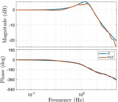
To assess the ez-width of our admittance controlled prosthetic hand, we first conducted a system identification experiment to identify the unknown dynamics of the prosthesis controller and plant, Hc and Hp respectively. We conducted a short experiment where the prosthetic hand was excited by an input signal that commanded the prosthesis to a specific position. The output position was recorded and compared to the input. The model of the prosthesis dynamics to be identified is defined as a black box containing dynamics of HcandHp. A multisine was used as input signal because it is periodic, contains power only at the desired frequencies and allows for the detection of non-linear distortions to certain degree. To prevent leakage, frequencies equal to an integer multiple of the frequency resolution are included. This way each harmonic fits exactly an integer number of times in the multisine signal [29]. The multisine had a period of 120 s (sampled at 100 Hz) and contained 80 frequencies ranging from 0.05 Hz to 4.95 Hz. The variance of the signal was optimized with respect to its amplitude by crest optimization using MATLAB command iddinput. Three trials with three different amplitudes were carried out: 20%, 50% and 100% of allowed HOC. These measurements yielded the Frequency Response Function (FRF) for the three amplitudes.
Experimental tasks and outcome measures
Three intact-limb subjects (aged 24.3 ±1.52) participated in this study and completed three experimental tasks. One subject had previous experience with MS-modelling and MYO control, but not with admittance based control. None of the rest had previous experience with MS-modelling or admittance based control. For ease of reading, the EMG-driven MS model based and admittance controlled prosthesis with environment force feedback is named MS+Adm+Fb, while the EMG-driven MS model with no admittance, i.e. the scheme presented by Sartori et al. in [13], is named MS+NoAdm. For the experimental tasks, only HOC was used as the Michelangelo hand could not grasp an object and
Fig. 7. Set up for blind object experiment. A wall is placed between the subject and the spring so no visual feedback is present during the experiment. Furthermore, the subject is deprived from auditory feedback by wearing noise-cancelling headphones.
pronate/supinate at the same time. This did not affect the goals of the experiments but limited the tasks to 1 DOF. The goals of the experimental tasks were fivefold:
• To evaluate to what extent MS+Adm+Fb control accounts for external forces when compared to MS+NoAdm when neither visual of auditory feedback are present.
• To assess if MS+Adm+Fb control scheme allows for
more accurate and precise grasp force control when compared to MS+NoAdm.
• To assess the robustness of the control methods regarding
undesired commands or unexpected commands produced by the EMG crosstalk between muscles.
• To determine which control strategy provided the most intuitive control when grasping new objects during un-trained conditions.
• To assess the computational performance of the frame-work for both control strategies.
The experimental procedures were carried out on two ses-sion on two consecutive days. In the first sesses-sions, a muscu-loskeletal model was scaled and calibrated to match subject’s anthropometry and force-generating capacity. Furthermore, the subject was trained to use both control methods and performed trials for the first two experimental tasks. The subject was also equipped with the Michelangelo and invited to grasp different objects. A proper training for the specific functional task was not given to the subject. The reason for this was to test the intuitiveness of both control methods when presented to new, untrained conditions and objects. During the second session, the subject-specific model was used for the online prosthesis control experimental tasks. Online control tests were performed with no model re-calibration.
[image:29.612.88.263.54.187.2] [image:29.612.349.526.55.189.2]24
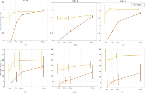
headphones to prevent auditory feedback when the object was grasped, as this feedback may prevent them from squeezing the object. The subjects were in control of the prosthesis HOC and asked to close it with varying levels of the maximal voluntary contraction (MVC). The measured MVC was plotted against the reference MVC levels in the computer screen as the only feedback to the subject. Subjects performed 3 trials with each control strategy (i.e. MS+Adm+Fb and MS+NoAdm). One trial consisted of 120 seconds partitioned in 24 MVC intervals of 5 seconds each. Four MVC levels were used as reference: 0%, 5%, 10%, 30%. The reference MVC levels were presented in a stair case form, where a 0% MVC was interleaved between each non-zero MVC levels. This fact helped to track the performance of the prosthesis when no command is sent but an external force is present. The displacement due to interaction forces was video-recorded for post-experiment analysis with the help of the ruler placed in the experimental setup (Fig. 6). This experiment allows to test the performance on grasp force control of the two control methods and to what extent they can account for external forces when no visual and auditory feedback of the prosthesis are given to the user. We hypothesized that MS+NoAdm control would cause higher interaction forces than during MS+Adm+Fb. Therefore, the outcome measure of this experiment were the displacement on the spring and the mean interaction force for each MVC level, where higher interaction forces were considered as possible damage or high deformation to the object or prosthesis.
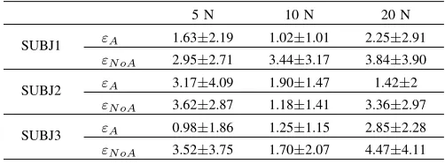
2) Force tracking: For this task the set up was the same as for the previous one. The subjects were asked to grab the object by generating appropriate EMG commands to follow a reference force line shown in the computer screen as accurately as possible with varying interaction force levels. Subjects performed 3 trials with each control strategy (i.e. MS+Adm+Fb and MS+NoAdm). One trial consisted of 120 seconds partitioned in 12 intervals of 10 seconds each. Three interaction force reference levels were chosen: 5, 10 and 20 Newtons, which corresponded to 10 %, 20 % and 40% of the maximal force the subject could achieve, respectively. Force levels were presented in a stair case form, where each level was presented 4 times across the duration of the experiment (see Fig. 12). During the experiment, the interaction force between the object and the Michelangelo hand was measured and plotted in the same screen. The experiment was performed with MS+Adm+Fb and MS+NoAdm. The object used was a spring with specific stiffness ke as discussed in section III-A. During MS+NoAdm control, the velocity commanded to the prosthetic hand is proportional to the input force, for which subjects would need to carefully produce reference velocities to achieve the reference interaction force. Because MS+Adm+Fb control can account for the interaction forces, we hypothesized that this control method would allow to reach faster balance between the subjects’ force and the interaction force for a finer grasp force control. Therefore, the outcome measures for this experiment are the absolute mean error between the reference interaction force and measured interaction force, the variability of the measured interaction force and the goodness of fit between the reference interaction force and measured interaction force. The absolute error is
[image:30.612.324.550.60.156.2](a) (b)
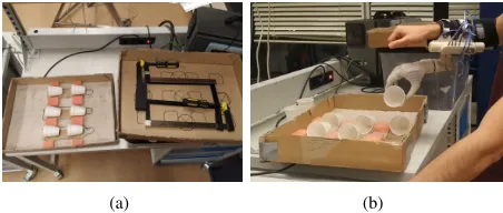
Fig. 8. Setup for functional task. Subject wore the prosthetic hand and moved cups from the box on the table to a higher positioned box.
taken as a measure of accuracy, while the variability of the measured forces is expressed as the interquartile range (IQR) and used to evaluate the consistency in the control of force (i.e., precision). The goodness of fit is evaluated in terms of R2 value and gives information on how good the subjects could follow the reference force levels. TheR2value, for each
MS+Adm+Fb and MS+NoAdm, is computed as the combined mean R2 value across all trials of each staircase period .
3) Functional task: For this task, the subjects were equipped with the Michelangelo hand and asked to grasp and move plastic cups from a box on a table to a higher positioned box (Fig. 8). Plastic cups were chosen as they are non-stiff objects and provide visual feedback when broken. The task was performed with the two control strategies for both untrained and trained conditions. Between conditions, the subjects were given several trials until he was familiarized with both control strategies and therefore trained to accomplish the task. The subjects were asked to transport 6 cups from one box to another 5 times non-stop, i.e. when all 6 cups were transported to the higher box they were transported back to the first box.
This experiment can show the usability of the MS+Adm+Fb in a real situation while assessing the robustness of both con-trol methods when the position of the arm is changed during the task. The primary outcome measure of this experiment is the number of broken or dropped cups during manipulation and the secondary outcome is the number of transported cups per minute (cpm). We hypothesized that MS+Adm+Fb would allow for more intuitive control and faster manipulation of the cups while a safe interaction force is achieved, breaking and dropped less cups than with MS+NoAdm.
The computational performance was assessed in terms of mean and variance of the computational speed for all frame-work components across all trials.
The subjects performed the experiments in order of increas-ing complexity: first the blind object test (no direct force control), force tracking (fine force control) and finally the functional task (force control during real situation).
III. RESULTS

![Fig. 5.Admittance and impedance causality of prosthesis-environmentmotion caused by interaction with the prosthesis into a reaction torque,prosthetic device andinteraction (modified from [21])](https://thumb-us.123doks.com/thumbv2/123dok_us/9634212.465884/28.612.355.518.64.148/admittance-impedance-prosthesis-environmentmotion-interaction-prosthesis-prosthetic-andinteraction.webp)