Munich Personal RePEc Archive
Passive Control of Spar Type Floating
Wind Turbine using Effective Economic
Optimal Design Values
Khatri, Krishna
University Visvesvaraya, College of Engineering
1 June 2019
Online at
https://mpra.ub.uni-muenchen.de/94447/
Passive Control of Spar Type Floating Wind Turbine using Effective
Economic Optimal Design Values
Krishna Khatri
University Visvesvaraya, College of Engineering Abstract
This paper studies the performance of a passive linear tuned mass damper on controlling motion of a floating wind turbine. Controlled and uncontrolled analytical models of the spar FWT is
established using Newton’s second law and conservation of angular momentum theory. The
aerodynamic, hydrodynamic, mooring and buoyancy forces are determined and coupled with the system. For the controlled model, the TMDs are located in different locations and are tuned to different frequency ratios to reduce the motion of the FWT in different directions. The economic optimal design values are considered for the passive controller. The control performance is evaluated by the reduction of root mean square response in each degree of freedom. The results reveals that the linear TMD tuned to the frequency of pitch degree of freedom reduces the translational motion and rotational motion by 5% and 12% respectively. However, tuning the linear tuned mass damper to the frequency of surge degree of freedom provides 8% and 6% motion reduction in translational and rotational degrees of freedom. Also, it has been shown that installing the linear TMD inside the spar is more effective than installing the TMD inside the nacelle.
Keywords: Spar floating wind turbine; conservation of angular momentum; linear tuned mass damper; passive control
1. Introduction
Due to the advantages of renewable energies over the fossil fuels, renewable energies have been attractive in different engineering fields [1]-[12]. Offshore wind turbines offer larger renewable power generation in comparison with the onshore wind turbines due to steadier and stronger wind speed in marine areas. In many countries, areas with allowable water depth to install offshore fixed wind turbines are highly limited and hence, floating wind turbines are more attractive than the fixed offshore wind turbines. In addition, due to higher wind speeds and possibility of generating higher electrical power in locations farther from the shore, the wind turbine size has increased which increases the flexibility of the wind turbine structures. Therefore, structural control methods have been investigated to reduce the motion and vibrations of the floating wind turbine.
vibrations of offshore wind turbines [22], [23]. Recorded met ocean data reveals that real wind and wave loadings are not in one direction. Therefore researchers introduced passive controlling methods which are able to reduce the vibrations in different directions [24]–[28].
In addition to passive controlling methods, active and semi-active controlling methods have also been investigated to reduce the vibrations of the offshore wind turbines. Active tendons were installed inside the blades to reduce the edgewise and flapwise vibrations of the blades [29], [30]. Semi-active controlling methods require much smaller energy input in comparison with the active controlling methods. It was shown that semi-active controlling methods are more effective than passive controlling methods in reducing the vibrations of offshore wind turbines [31]–[34].
The above literature review shows that most mentioned researches have focused on reducing vibrations of fixed offshore wind turbines. Only some studies have studied the vibration reduction of floating wind turbines which mostly have simplified the structural modeling of the floating wind turbine either to in-plane directions or by linear simplified methods. Therefore, this paper studies the effectiveness of a passive linear TMD in reducing vibrations of a spar floating wind turbine. The floating wind turbine is modeled using conservation of momentum method which models the non-linarites of the structure. The aerodynamic, hydrodynamic, hydrostatic and mooring loads are determined via accurate methods. The TMD frequency is tuned to different degrees of freedom frequencies. Also, the linear TMD is placed in different locations to determine the most optimum location in reducing the root mean square response of the floating wind turbine. It is shown that the linear TMD tuned to the frequency of pitch degree of freedom reduces the translational motion and rotational motion by 5% and 12% respectively. However, tuning the linear tuned mass damper to the frequency of surge degree of freedom provides 8% and 6% motion reduction in translational and rotational degrees of freedom. Also, it has been shown that installing the linear TMD inside the spar is more effective than installing the TMD inside the nacelle.
2. Analytical model
In this section, the equations of motion for the floating wind turbine are derived by using conservation of angular momentum and Newton’s second law. It is essential to introduce different
coordinate systems and to determine the system’s equations of motion with respect to the
mentioned coordinates. Also, the external forces and moments, which are resulted from buoyancy, hydrodynamic, wind, and mooring cables are determined.
The floating wind turbine is considered as two rigid bodies, the tower and the rotor and nacelle assembly. (X, Y, Z) is earth-fixed global coordinate system located at system’s center of mass.
1 1 1
(x , y , z ) and (x , y , z )2 2 2 are body fixed and are located at first and second body’s center of mass
respectively. (x , y , z )s s s is the coordinate system for the entire system, which is assumed to be
parallel to (x , y , z )1 1 1 and is located on the system’s center of mass [35]–[37].
Six unknown degrees of freedom is related to the first body which includes three translational,and 3 rotational degrees of freedom. Additionally, two known degrees of freedom for rotor spinning,
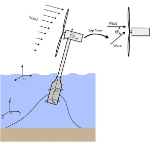
The schematic image of the floating wind turbine and the coordinates are illustrated in Fig. 1. The
[image:4.612.152.456.140.425.2]misalignment angle between wind and wave loading is denoted by θ.
Fig. 1. Schematic image of the spar type FWT
Newton's second law is applied to the system to determine the translational equations:
1 2
(m m ) a
I I
s
C C
G
F
(1)where
FCI is the summation of all external forces. Also,1
m and m2 denote the mass of first and second body respectively. Additionally, the linear acceleration of the system which is shown as
a I s
C
G is equal to X X1, 2,X3.
To determine the rotational equations of motion, the conservation of angular momentum theory is used as follows:
1 1
H
s s
C
s s
G B G
M H
(2)where
M is the external moment resulted from external loadings. Also,s
s G
H denotes the angular momentum of entire system in Cs coordinate system.H s
s
G is the change of momentum amplitude
for the entire system and 1 1 C B
describes the absolute angular velocity. The total angular momentum
The angular momentum of the system can be determined as follows:
'
s
s
G s s
H I H (3)
where Is is the inertia tensor and H' ( IBsin , IB cos , ICyaw). The absolute time derivative of
angular momentum of the system can be determined as:
'
s
s
G s s s s
H I I H (4)
By substituting the angular momentum of the system and its derivative into the newton’s second
law and conservation of angular momentum theory, the equations of the motion can be written in a matrix form as:
wave wind buoy mooring gravity
MXCXKX Q Q Q Q Q (5)
It should be noted that, M, C and K are the mass, damping and stiffness matrixes which are time variant. Variables Qwave,Qwind,Qbuoy,Qmooring,Qgravityare the force and moment vectors resulted from
the external loadings.
3. Loading
The mooring forces, buoyancy force, hydrodynamic and wind loads are derived in this section
3.1.Wind Load
The most dominant load on offshore wind turbine is the wind loading. Therefore, it is important to model this force accurately. The mean velocity is calculated using logarithmic wind profile:
0
0
log( / )
( )
log( / )
hub ref
V z z
v z
H z (6)
where Vhubis the mean velocity at the hub height. z0is the roughness length. The Kaimal spectrum
model is used to model the turbulent component of the wind.
After determining the wind velocity on the wind turbine, the blade element momentum method is used to determine the lift and drag forces acting on the wind turbine blade. The lift and rag forces can be expressed as follows:
2 2
1 1
, F
2 2
L a rel l D a rel d
F V cC V cC (7)
where a is the density of air andcis the chord length and the CN and CT are the normal and the tangential coefficients.
3.2.Wave load
The wave force acting on circular cylindrical structural members can be estimated using Morison’s
equation as follows:
2 2
1
2 4 4
I
M d rt rt a t m n
f C DV V C D V C D V (9)
where Cd ,Ca andCm are the drag, added mass and inertia coefficient respectively. Also, is the
sea water density and D is the diameter of the hull. Vt ,Vnand Vrtare the normal component of
wave acceleration, structural acceleration and velocity of the water particle relative to the tower. The normal component of water particle acceleration is determined by: I ( I)
n z z
V u V u . Parameter V represents the wave acceleration vector in theCIcoordinate system and
I z
u is the unit vector along the central axis of the tower in theCI coordinate system, which is equal to: (0, 0,1)
I z s I
u T .
The structural velocity and acceleration are calculated by the following equations:
1 1
1 2 3 /
( , , ) ( )
s
C
t s I B i G
V X X X T r (10)
1 1 1
1 1 1
1 2 3 / /
( , , ) ( ( ))
s s
C C C
t s I B i G B B i G
V X X X T r r (11)
Where ri G/ sis the vector radius from CM of the system to the segment with unit length. The normal
velocity of the water particle relative to the tower is expressed asVrt uzI(VrwtuzI). The relative
velocity of the wave to the segment of the submerged tower is shown as Vrwt V Vt in which Vis
the wave kinematic velocity.
To define the velocity and acceleration of the water particles, it is considered that the sea waves have a regular sinusoidal shape. According to this theory the surface elevation, velocity and acceleration of particles are computed:
( , ) cos
2 H
y t ky t
(12)
(0, , )
cosh ( )
cos( )
sinh
cosh ( )
sin( )
sinh
V u v
H k x d
u ky t
T kd
H k x d
v ky t
T kd (13) 2 2 2 2
(0, , )
2 cosh ( )
sin( )
sinh
2 cosh ( )
cos( )
sinh
V u v
H k x d
u ky t
kd T
H k x d
v ky t
where H , T ,kand are wave height, time period of wave, wave number and angular wave frequency respectively. The wave force on the platform of the system and the wave moment in the
s
C system is computed by numerically integrating over the submerged length of the tower as follows: / ( ( ) s I wave M I wave i G I s M
F f
M r T f dz
(15)The wave loading along surge and sway by considering the wind-wave misalignment angle, , can be expressed as:
,
,
cos sin
wave surge wave
wave sway wave
F F F F (16) 3.3.Mooring forces
To determine the mooring load, a dynamic linking library, Moordyn [38], is coupled to the MATLAB codes. This model uses a lumped mass approach to discretize the cable dynamics over the length of the mooring line.
3.4.Buoyancy Load
The instantaneous buoyancy of the floating system can be expressed as follows:
2 1
(0, 0, )
I B
F g r h (18)
where is the water density, r is the radius of the cylinder and h1 is the instant submerged length of the cylinder,
To determine the moments, the center of buoyancy should be calculated, if the distance between center of buoyancy and CM of the system is assumed as rB G/ s ( B, B, B), the distance can be
expressed as: 2 31 33 1 2 32 33 1
2 2 2 31 32 1 2 33 1 4 4 ( ) 2 8 B B B G tt r tt h tt r tt h
r tt tt h h tt h (19)
The resulting external moment is defined as /
s I s
s I
B B G C C B
M r T F
4. Simulation and Results
The NREL 5MW spar type wind turbine model is used as a case study. The wind speed is considered to be 12 m/s with a turbulence intensity of 10%. The significant wave height is 2 m
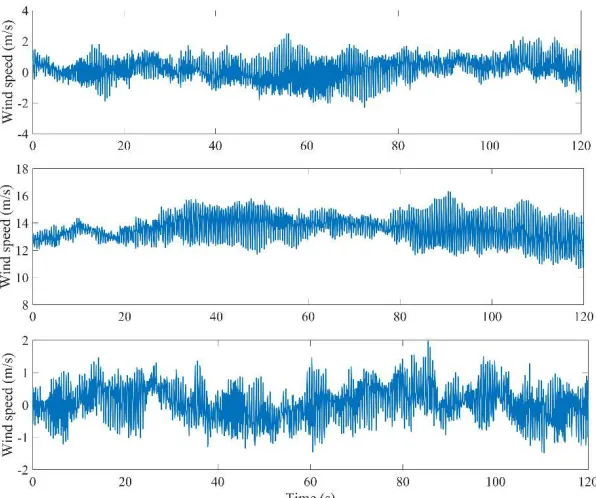
should be noted that the wind time history is generated in three different axes and the wind turbine is facing the wind speed with higher values.
Fig. 2. Three dimensional wind time history (v12 /m s and turbulence intensity of 10%)
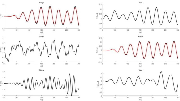
Fig. 3. Vibration mitigation of FWT with linear TMD frequency tuned to 0.008 Hz.
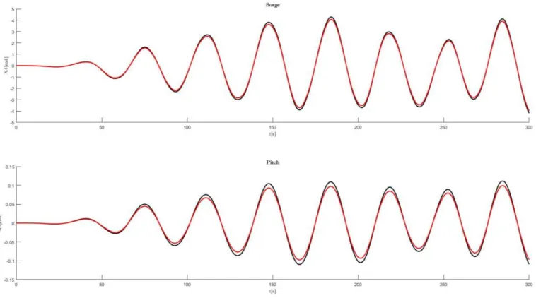
[image:9.612.116.492.437.652.2]Fig. 4 shows the translational and rotational motion reduction between the baseline wind turbine and controlled case. The passive linear TMD is installed inside the spar and the frequency is tuned to 0.03 Hz which is the natural frequency of the wind turbine system in rotational degree of freedom. It can be seen that the motion of the floating wind turbine in surge and pitch degree of freedom has reduced. But, the reduction in pitch direction is more significant than the reduction in surge direction.
Fig. 4. Vibration mitigation of FWT with linear TMD frequency tuned to 0.03 Hz.
which is the natural frequency of the wind turbine system in rotational degree of freedom. It can be seen that the motion of the floating wind turbine in surge and pitch degree of freedom has reduced. By comparing the results presented in Fig. 5 and Fig. 4, it can be concluded that installing the TMD inside the spar is more effective than installing it inside the nacelle.
Fig. 5. Vibration mitigation of FWT with linear TMD frequency tuned to 0.03 Hz and installed inside the nacelle.
5. Conclusion
In this paper, the spar floating wind turbine is modeled using conservation of momentum method which considers the nonlinearities of the system in the model. A linear tuned mass damper is installed in nacelle and the platform. The TMD is also tuned to different frequencies to evaluate the effectiveness of the TMD in reducing the vibrations of the floating wind turbine in different degrees of freedom. It is shown that the linear TMD tuned to the frequency of pitch degree of freedom reduces the translational motion and rotational motion by 5% and 12% respectively. However, tuning the linear tuned mass damper to the frequency of surge degree of freedom provides 8% and 6% motion reduction in translational and rotational degrees of freedom. Also, it has been shown that installing the linear TMD inside the spar is more effective than installing the TMD inside the nacelle.
References
[1] Tajalli, Seyede Zahra, Seyed Ali Mohammad Tajalli, Abdollah Kavousi-Fard, Taher Niknam, Morteza Dabbaghjamanesh, and Shahab Mehraeen. "A Secure Distributed Cloud-Fog Based Framework for Economic Operation of Microgrids." In 2019 IEEE Texas Power and Energy Conference (TPEC), pp. 1-6. IEEE, 2019.
[3] Taherzadeh, Erfan, Shahram Javadi, and Morteza Dabbaghjamanesh. "New Optimal Power Management Strategy for Series Plug-In Hybrid Electric Vehicles." International Journal of Automotive Technology 19, no. 6 (2018): 1061-1069.
[4] Taherzadeh, Erfan, Morteza Dabbaghjamanesh, Mohsen Gitizadeh, and Akbar Rahideh. "A new efficient fuel optimization in blended charge depletion/charge sustenance control strategy for plug-in hybrid electric vehicles." IEEE Transactions on Intelligent Vehicles 3, no. 3 (2018): 374-383.
[5] Dabbaghjamanesh, Morteza, Shahab Mehraeen, Abdollah Kavousi-Fard, and Farzad Ferdowsi. "A New Efficient Stochastic Energy Management Technique for Interconnected AC Microgrids." In 2018 IEEE Power & Energy Society General Meeting (PESGM), pp. 1-5. IEEE, 2018.
[6] Dabbaghjamanesh, Morteza, Shahab Mehraeen, Abdollah Kavousifard, and Mosayeb Afshari Igder. "Effective scheduling operation of coordinated and uncoordinated wind-hydro and pumped-storage in generation units with modified JAYA algorithm." In 2017 IEEE Industry Applications Society Annual Meeting, pp. 1-8. IEEE, 2017.
[7] Dabbaghjamanesh, Morteza, Abdollah Kavousi-Fard, and Shahab Mehraeen. "Effective scheduling of reconfigurable microgrids with dynamic thermal line rating." IEEE Transactions on Industrial Electronics 66, no. 2 (2019): 1552-1564.
[8] Khazaei, Peyman, Morteza Dabbaghjamanesh, Ali Kalantarzadeh, and Hasan Mousavi. "Applying the modified TLBO algorithm to solve the unit commitment problem." In 2016 World Automation Congress (WAC), pp. 1-6. IEEE, 2016.
[9] Khazaei, P., S. M. Modares, M. Dabbaghjamanesh, M. Almousa, and A. Moeini. "A high efficiency DC/DC boost converter for photovoltaic applications." International Journal of Soft Computing and Engineering (IJSCE) 6, no. 2 (2016): 2231-2307.
[10] Rakhshan, Mohsen, Navid Vafamand, Mokhtar Shasadeghi, Morteza Dabbaghjamanesh, and Amirhossein Moeini. "Design of networked polynomial control systems with random delays: sum of squares approach." International Journal of Automation and Control 10, no. 1 (2016): 73-86.
[11] Ashkaboosi, M., Nourani, S.M., Khazaei, P., Dabbaghjamanesh, M. and Moeini, A., 2016. An optimization technique based on profit of investment and market clearing in wind power systems. American Journal of Electrical and Electronic Engineering, 4(3), pp.85-91.
[12] Dabbaghjamanesh, M., A. Moeini, M. Ashkaboosi, P. Khazaei, and K. Mirzapalangi. "High Performance Control of Grid Connected Cascaded H-Bridge Active Rectifier Based on Type II-Fuzzy Logic Controller with Low Frequency Modulation Technique." International Journal of Electrical & Computer Engineering (2088-8708) 6, no. 2 (2016).
[13] P. J. Murtagh, A. Ghosh, B. Basu, and B. M. Broderick, “Passive control of wind turbine vibrations
including blade/tower interaction and rotationally sampled turbulence,” Wind Energy, vol. 11, no. 4, pp. 305–317, Jul. 2008.
[14] M. A. Lackner and M. A. Rotea, “Passive structural control of offshore wind turbines,” Wind Energy, vol. 14, no. 3, pp. 373–388, Apr. 2011.
[15] B. Zhao, H. Gao, Z. Wang, and Z. Lu, “Shaking table test on vibration control effects of a monopile offshore wind turbine with a tuned mass damper,” Wind Energy, vol. 21, no. 12, pp. 1309–1328, Dec. 2018.
[16] M. Ghassempour, G. Failla, and F. Arena, “Vibration mitigation in offshore wind turbines via tuned mass
damper,” Eng. Struct., vol. 183, pp. 610–636, Mar. 2019.
[17] J. Yang, E. M. He, and Y. Q. Hu, “Dynamic modeling and vibration suppression for an offshore wind
turbine with a tuned mass damper in floating platform,” Appl. Ocean Res., vol. 83, pp. 21–29, Feb. 2019. [18] Z. Zhang, S. R. K. Nielsen, B. Basu, and J. Li, “Nonlinear modeling of tuned liquid dampers (TLDs) in
rotating wind turbine blades for damping edgewise vibrations,” J. Fluids Struct., vol. 59, pp. 252–269, Nov. 2015.
[19] Q. Jin, X. Li, N. Sun, J. Zhou, and J. Guan, “Experimental and numerical study on tuned liquid dampers for
2007.
[20] M. H. Alkmim, M. V. G. de Morais, and A. T. Fabro, “Vibration Reduction of Wind Turbines Using Tuned Liquid Column Damper Using Stochastic Analysis,” J. Phys. Conf. Ser., vol. 744, no. 1, p. 12178, Sep. 2016.
[21] S. Colwell and B. Basu, “Tuned liquid column dampers in offshore wind turbines for structural control,” Eng. Struct., vol. 31, no. 2, pp. 358–368, 2009.
[22] H. Zuo, K. Bi, and H. Hao, “Using multiple tuned mass dampers to control offshore wind turbine vibrations
under multiple hazards,” Eng. Struct., vol. 141, pp. 303–315, 2017.
[23] V.-N. Dinh and B. Basu, “Passive control of floating offshore wind turbine nacelle and spar vibrations by
multiple tuned mass dampers,” Struct. Control Heal. Monit., vol. 22, no. 1, pp. 152–176, Jan. 2015. [24] G. M. Stewart and M. A. Lackner, “The impact of passive tuned mass dampers and wind–wave
misalignment on offshore wind turbine loads,” Eng. Struct., vol. 73, pp. 54–61, 2014.
[25] Z. Zhang, A. Staino, B. Basu, and S. R. K. Nielsen, “Performance evaluation of full-scale tuned liquid dampers (TLDs) for vibration control of large wind turbines using real-time hybrid testing,” Eng. Struct., vol. 126, pp. 417–431, Nov. 2016.
[26] C. Sun and V. Jahangiri, “Bi-directional vibration control of offshore wind turbines using a 3D pendulum
tuned mass damper,” Mech. Syst. Signal Process., vol. 105, pp. 338–360, May 2018.
[27] C. Sun and V. Jahangiri, “Fatigue damage mitigation of offshore wind turbines under real wind and wave
conditions,” Eng. Struct., vol. 178, pp. 472–483, Jan. 2019.
[28] V. Jahangiri and C. Sun, “Integrated bi-directional vibration control and energy harvesting of monopile
offshore wind turbines,” Ocean Eng., vol. 178, pp. 260–269, Apr. 2019.
[29] B. Fitzgerald and B. Basu, “Cable connected active tuned mass dampers for control of in-plane vibrations of
wind turbine blades,” J. Sound Vib., vol. 333, no. 23, pp. 5980–6004, Nov. 2014.
[30] A. Staino, B. Basu, and S. R. K. Nielsen, “Actuator control of edgewise vibrations in wind turbine blades,” J. Sound Vib., vol. 331, no. 6, pp. 1233–1256, Mar. 2012.
[31] C. Sun, “Semi-active control of monopile offshore wind turbines under multi-hazards,” Mech. Syst. Signal Process., vol. 99, pp. 285–305, Jan. 2018.
[32] J. Arrigan, V. Pakrashi, B. Basu, and S. Nagarajaiah, “Control of flapwise vibrations in wind turbine blades using semi-active tuned mass dampers,” Struct. Control Heal. Monit., vol. 18, no. 8, pp. 840–851, Dec. 2011.
[33] J. Chen, C. Yuan, J. Li, and Q. Xu, “Semi-active fuzzy control of edgewise vibrations in wind turbine blades
under extreme wind,” J. Wind Eng. Ind. Aerodyn., vol. 147, pp. 251–261, Dec. 2015.
[34] C. Huang, J. Arrigan, S. Nagarajaiah, and B. Basu, “Semi-Active Algorithm for Edgewise Vibration Control
in Floating Wind Turbine Blades,” in Earth and Space 2010, 2010, pp. 2097–2110.
[35] L. Wang and B. Sweetman, “Simulation of large-amplitude motion of floating wind turbines using
conservation of momentum,” Ocean Eng., vol. 42, pp. 155–164, 2012.
[35] V. Jahangiri and M. M. Ettefagh, “Multibody Dynamics of a Floating Wind Turbine Considering the
Flexibility between Nacelle and Tower,” Int. J. Struct. Stab. Dyn., vol. 18, no. 6, 2018.
[37] L. Wang and B. Sweetman, “Multibody dynamics of floating wind turbines with large-amplitude motion,” Appl. Ocean Res., vol. 43, pp. 1–10, 2013.