ISSN Print: 2327-5219
DOI: 10.4236/jcc.2017.512008 Oct. 30, 2017 70 Journal of Computer and Communications
Visualization of 3-Dimensional Vectors in a
Dynamic Embryonic System—WormGUIDES
Eric Wang
1,2, Anthony Santella
3, Zi Wang
1, Dali Wang
1,4, Zhirong Bao
31Department of Electric Engineering and Computer Science, University of Tennessee, Knoxville, TN, USA 2Coding Club, Farragut High School, Knoxville, TN, USA
3Developmental Biology Program, Memorial Sloan Kettering Cancer Center, New York, NY, USA 4Environmental Science Division, Oak Ridge National Laboratory, Oak Ridge, TN, USA
Abstract
WormGUIDES is an open-source dynamic embryonic system designed to fa-cilitate global understanding of cellular decisions in the developing nervous system of the nematode C. elegans. WormGUIDES was designed to allow in-vestigation and exploration of the observational results of the C. elegans life cycle from laboratory experiments. In the process of a mechanistic C. elegans model development, some functionalities of WormGUIDES needed to be en-hanced to support model validation and verification. In this study, a new way to visualize 3-dimentional vectors within WormGUIDES was investigated and presented. Then, the practical values of this method were demonstrated by visualizing two biologically significant directions (i.e., division orientation and cell polarity) of individual embryonic cells in C. elegans. Lastly, a mathematic approach was designed to illustrate the differences between these two sets of vectors and provide easy indications of the location of these individual cells that have large data discrepancies within the C. elegans embryonic system.
Keywords
Embryonic Data Visualization, WormGUIDES, Workflow,
Software Architecture, Division Orientation, Cell Polarity, C. elegans
1. Introduction
In the past several years, a consortium of biologists, computer scientists, and microscopists from the Memorial Sloan Kettering Cancer Center, Yale Univer-sity, the University of Connecticut, and the National Institute of Health have worked together to create a novel systems-level resource that will facilitate ex-amination of cellular decisions in the developing nervous system of the nema-How to cite this paper: Wang, E., Santella,
A., Wang, Z., Wang, D.L. and Bao, Z.R. (2017) Visualization of 3-Dimensional Vectors in a Dynamic Embryonic Sys-tem—WormGUIDES. Journal of Computer and Communications, 5, 70-79.
https://doi.org/10.4236/jcc.2017.512008
Received: September 19, 2017 Accepted: October 27, 2017 Published: October 30, 2017
Copyright © 2017 by authors and Scientific Research Publishing Inc. This work is licensed under the Creative Commons Attribution International License (CC BY 4.0).
DOI: 10.4236/jcc.2017.512008 71 Journal of Computer and Communications tode C. elegans. This resource, used for global understanding in dynamic em-bryonic systems, is WormGUIDES [1]. WormGUIDES was solely a mobile app until 2016, when a desktop version of WormGUIDES was released with detailed information on cell shapes, note-taking, and sharing functionality, as well as sin-gle-cell information summaries [2]. Along with current development of agent-based embryogenesis modeling [3] [4], we would like to extend the WormGUIDES functionality for model verification and validation. This process is necessary in order to achieve an efficient way of comparing any 3D vectors through visualization. In this paper, we first summarize the software architecture of WormGUIDES, and then present a method to visualize the 3-dimentional vectors with RGB values. Finally, we demonstrate the practical use of this me-thod to visualize two sets of 3-dimentional vectors with significant biological meanings: division orientation and cell polarity. The experiment can be ex-tended to other vectors to facilitate further model calibration and verification.
2. Software Architecture of WormGUIDES
2.1. Computational Platform and Software Architecture
The source code for the desktop version of WormGUIDES is located on GitHub for free download [5]. The computational platforms used in the study are a MacBook Air and a workstation at MSKCC. The detailed WormGUIDES instal-lation instructions are available online [6].
Currently, there are two important functions embedded within Worm-GUIDES. One of these functions is designed to contain and display the C. ele-gans lineage tree information from previous experiments [7] and after gene mu-tation & manipulation [8]. The other important function is to allow access to and visualize the connectome, the complete neural connectivity record which is uniquely available for C. elegans [9].
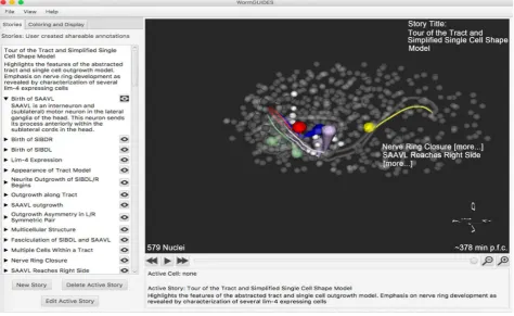
Additionally, WormGUIDES contains several utilities to support user search and query. The WormGUIDES interface is illustrated in Figure 1.
DOI: 10.4236/jcc.2017.512008 72 Journal of Computer and Communications
Figure 1. The main interface of WormGUIDES.
2.2. Data Visualization Procedure within WormGUIDES System
WormGUIDES provides the intuitive creation and sharing of interactive visua-lizations. Users can create custom color schemes to highlight features of interest. Multiple color layers can be combined to create an interactive 4D illustration of key events or features. This view of the embryo can then be shared with others encoded in a URL text string. This functionality can be used to visualize arbi-trary single cell data superimposed on the model by computing a mapping from data into RGB. A color space and outputting a URL which assigns each cell in the embryo a unique data-driven color.2.3. The Visualization of 3D Vectors
DOI: 10.4236/jcc.2017.512008 73 Journal of Computer and Communications R, G, and B values, respectively, we can create a colored system of cells in WormGUIDES that defines in which direction the mother cell will split into its daughters.
3. Practical Applications of Data Visualization
An important example of a vector to visualize is cell division orientation, defined as the direction in which a parent cell splits into two daughter cells. Cell division orientation is important for morphogenesis, cell fate, and tissue homeostasis. In this section, we use our color schemes to visualize the division of orientation, measured from tracked cell positions. In C. elegans embryogenesis, the division orientation is closely related to another concept, cell polarity, which is defined as “the asymmetric organization of several cellular components, including its plas-ma membrane, cytoskeleton or organelles” [10]. Cell polarity causes asymmetric organization within a cell, such as localization of molecules. Cell polarity im-pacts the division orientation [11] since the mitotic spindle can be oriented based on the asymmetric localization of regulators, such as PAR proteins, or the Wnt signaling pathway. However, unlike division orientation, cell polarity caused by many factors and cannot be easily modeled. As a result, we first make several assumptions to derive a cell polarity from a division orientation. Then we can visualize the cell polarity and quantify the differences between division orientation and cell polarity to identify the sources of these differences.
3.1. Calculation and Visualization of Division Orientation from
Observation
A MatLab program is created to calculate the division orientations from obser-vational datasets, derived directly from the microscopic images from Dr. Bao’s lab. Each dataset contains the cell list at a specific timestamp during the observa-tion. The interval of observation is around 60 seconds. The pseudo code of divi-sion orientation calculation is illustrated in Figure 2. First, we load the tracked
DOI: 10.4236/jcc.2017.512008 74 Journal of Computer and Communications cell locations. Then, we align the XYZ axes with the individual body axis of cell separately: X axis for the Anterior-posterior (AP) direction, the Y axis for the Ventral-dorsal (DV) direction, and the Z axis for the Left-right (LR) direction. The pseudo code of division orientation calculation is illustrated in Figure 2.
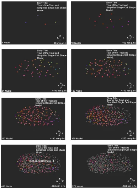
Following the procedure described in Section 2.4, the collection of visualiza-tion results is shown in Figure 3. As illustrated, each dot represents one nuclei in the embryo. The colors of the dots in the images above each represent the di-vision orientation of one of the cells, which is derived from the observational dataset. Each image is representative of a different point of time in the embryo’s development. From these images, we observe that the division orientation of AB related cells at each generation have similar colors, especially at the early devel-opment phase (before the 220 minutes after the beginning of embryo growth). This observation leads us to an assumption that the dominant driving force in each generation of AB-related cell development may be the same. It can also be used to estimate the cell polarity in the cell development.
3.2. Calculation and Visualization of Cell Polarity of Cells within
AB Sub-Lineage
In our study, we define cell polarity as the main factor for determining division orientation. As we previously mentioned in Section 3, it is difficult to model the cell polarity directly from observation. However, in Section 3.1 we observed that the division orientation of AB related cells at each generation have similar direc-tions at the early development phase. As a result, we may assume cell polarity for each cell in the AB sub-lineage tree in a generation is the same. The cell polarity of all the cells of same generation within AB sub-lineage tree is thereby calcu-lated by averaging the division orientations for the generation of cells. Then, adding the X, Y, and Z components of the vectors to get the main vector, norma-lizing this main vector, and splitting it back into components should allow the cell polarity to be easily mapped onto its respective RGB values.
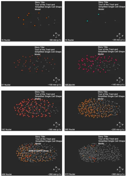
As illustrated in Figure 4, the cell polarity within AB lineage changes from generation to generation. The color of cell polarity in the first image is light green, which means the direction more aligns with Z axis, while the color of cell polarity in the second image is orange, which means the direction more aligns with X-Y plane. It is a very rapid change. From the third image, the colors of cell polarity vary within the range of orange and pink/red, which shows the direction is still aligned with the X-Y plane. The comparison between Figure 3 and Figure 4 shows differences of these two sets of vectors, so that we may need to reeva-luate of our methods and assumptions of cell polarity calculations. In the next section, we would like to quantify these differences to identify the sources for the major data discrepancy.
3.3. Quantification of Differences between Observed Division
Orientation and Calculated Cell Polarity
DOI: 10.4236/jcc.2017.512008 75 Journal of Computer and Communications
Figure 3. The division orientations of the cells at different times of the embryo’s development. The red and orange color majority
DOI: 10.4236/jcc.2017.512008 76 Journal of Computer and Communications
Figure 4. The visualization of cell polarities of cells within the AB sub-lineage. The rest cells are not relevant and are colored in gray.
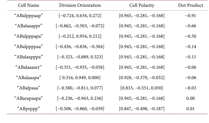
DOI: 10.4236/jcc.2017.512008 77 Journal of Computer and Communications Cell Polarity, a DotProduct function was developed in MatLab to quantify the discrepancy of these two set of vectors. Each vector is associated with individual cell that can be used to link the vectors between these two datasets. Since only the direction, not the quantity, of the vector is of interest, all the vectors are normalized first before the dot production operation. The results are easy to un-derstand: the closer the value of dot product is to 1, the closer the two individual vectors match. For the demonstration purpose, the top 10 cells with the large differences between these two vectors are listed in Table 1. The complete com-parison results are available in Dropbox [12].
As shown in Table 1, the two vectors associated with cell AB alpppaap have the biggest errors, the negative value (close to −1) meaning that these two vec-tors have almost completely opposite directions. It is also noticeable the large differences occurred at a later stage of development. The result also reiterates that at the early development phase the division orientations of AB related cells have similar division orientation.
4. Conclusions and Discussions
[image:8.595.198.541.535.737.2]WormGUIDES is an open-source dynamic embryonic system developed by col-laborations between Memorial Sloan Kettering Cancer Center, Yale, University of Connecticut Medical Center and the National Institute of Health. Worm-GUIDES can support the examination of cellular divisions in the developing nervous system of the nematode C. elegans. To facilitate mechanistic embryonic system model development, we need a visualization tool to identify the locations & ranges of 3D vector data and the discrepancy between 3D vectors datasets. In this paper, we have presented a new way to visualize 3D vectors within Worm-GUIDES. We have laid out the implementation details and demonstrated the functionality by visualizing both the division orientation and the calculated cell polarity of individual embryonic cells in AB sub-lineage of C. elegans. Different
Table 1. The differences (Dot Product) between the Division Orientation and Cell Polarity
of Cells within the AB Sub-lineage.
Cell Name Division Orientation Cell Polarity Dot Product “ABalpppaap” [−0.724, 0.634, 0.272] [0.945, −0.281, −0.168] −0.91 “ABalaaappr” [−0.862, −0.503, −0.072] [0.945, −0.281, −0.168] −0.66 “ABalpppapa” [−0.212, 0.954, 0.212] [0.945, −0.281, −0.168] −0.50 “ABalppppaa” [−0.456, −0.836, −0.304] [0.945, −0.281, −0.168] −0.14 “ABalaapppa” [−0.323, −0.889, 0.323] [0.945, −0.281, −0.168] −0.11 “ABalaaaarr” [−0.351, −0.935, −0.058] [0.945, −0.281, −0.168] −0.06 “ABalaaapa” [ 0.316, 0.949, 0.000] [0.928, −0.370, −0.032] −0.06 “ABalpaaa” [−0.580, −0.811, 0.077] [0.833, −0.551, 0.050] −0.03 “ABarapaapa” [−0.236, −0.943, 0.236] [0.945, −0.281, −0.168] 0.00
DOI: 10.4236/jcc.2017.512008 78 Journal of Computer and Communications hypotheses will be proposed in the C. elegan’s embryogenesis model develop-ment, especially for the cells that divide in the directory of D/V or LR, instead of AP. Therefore, this visualization and discrepancy quantification will provide in-formation to facilitate the identification of major factors for regulating cell divi-sion orientation. In addition, this tool can be used to provide intuitive access to information on the location properties of these individual cells with large data discrepancies.
Acknowledgements
This study is supported by an NIH research project grants (R01GM097576 and 2R01GM097576). Research in the Bao lab is also supported by an NIH center grant to MSKCC (P30CA008748).
References
[1] Santella, A., Catena, R., Kovacevic, I., Shah, P., Yu, Z.D., Marquina-Solis, J., Kumar, A., et al. (2015) WormGUIDES: An Interactive Single Cell Developmental Atlas and Tool for Collaborative Multidimensional Data Exploration. BMC Bioinformatics, 16, 189. https://doi.org/10.1186/s12859-015-0627-8
[2] C. elegans Tropic Meeting: Neuronal Development, Synaptic Function and Beha-vior, CeNeuro 2016, and Nagoya BNC Symposium.
http://www.bio.nagoya-u.ac.jp/~ceneuro2016/
[3] Wang, Z., Ramsey, B.J., Wang, D.L., Wong, K., Li, H.S., Wang, E. and Bao, Z.R. (2016) An Observation-Driven Agent-Based Modeling and Analysis Framework for
C. elegans Embryogenesis. PLoS ONE, 11, e0166551.
https://doi.org/10.1371/journal.pone.0166551
[4] Wang, Z., Wang, D.L., Li, H.S. and Bao, Z.R. (2017) Cell Neighbor Determination in the Metazoan Embryo System. Proceedings of the 8th ACM International Confe-rence on Bioinformatics, Computational Biology, and Health Informatics, Boston, MA, August 2017, 305-312.
[5] WormGUIDES Source Code in GitHUB.
https://github.com/tangydoris/WormGUIDES
[6] Wang, E. WormGUIDES Installation Guide with Eclipse. Available in Dropbox at
https://www.dropbox.com/s/v9uv0m109vsrhb4/WormGUIDES_installation_revise d_v1.0.docx?dl=0
[7] Bao, Z., Murray, J.I., Boyle, T., Ooi, S.L., Sandel, M.J. and Waterston, R.H. (2006) Automated Cell Lineage Tracing in Caenorhabditis elegans. Proceedings of the Na-tional Academy of Sciences of the United States of America, 103, 2707-2712.
https://doi.org/10.1073/pnas.0511111103
[8] Du, Z., Santella, A., He, F., Shah, P.K., Kamikawa, Y. and Bao, Z.R. (2015) The Reg-ulatory Landscape of Lineage Differentiation in a Metazoan Embryo. Developmen-tal Cell, 34, 592-607. https://doi.org/10.1016/j.devcel.2015.07.014
http://www.sciencedirect.com/science/article/pii/S1534580715004876
[9] White, J.G., Southgate, E., Thomson, J.N. and Brenner, S. (1986) The Structure of the Nervous System of the Nematode Caenorhabditis elegans: The Mind of a Worm. Philosophical Transactions of the Royal Society London, 314, 1-340.
DOI: 10.4236/jcc.2017.512008 79 Journal of Computer and Communications
[10] The Definition of Cell Polarity at Nature.com.
https://www.nature.com/subjects/cell-polarity
[11] Cowan, C.R. and Hyman, A.A. (2004) Asymmetric Cell Division in C. elegans: Cor-tical Polarity and Spindle Positioning. Annual Review of Cell and Developmental Biology, 20, 427-453.
https://doi.org/10.1146/annurev.cellbio.19.111301.113823
[12] Comparison of Division Orientation and Cell Polarity of Individual Cell within AB-Lineage. Available in Dropbox at