INTERCOM STATIONS
I N S T R U C T I O N M A N U A L
I-SERIES
i-Series Instruction Manual
2003 Clear-Com Intercom Systems All Rights Reserved
Part Number 810268 Rev. A Clear-Com Intercom Systems 4065 Hollis Street
Emeryville, CA 94608-3505 U.S.A
Clear-Com is a registered trademark of Clear-Com Intercom Systems.
The Clear-Com Logo is a registered trademark of Clear-Com Intercom Systems.
Matrix Plus is a registered trademark of Clear-Com Intercom Systems. Windows and Windows NT are registered trademarks of Microsoft Corp.
CONTENTS
IMPORTANT SAFETY INSTRUCTIONS
v
OPERATION
1-1
Description. . . 1-1 Operational Features. . . 1-1 i-Series Construction . . . 1-1 i-Series Modules . . . 1-2 Key Module . . . 1-2 Function Key Module. . . 1-2 Mic-Headset Module . . . 1-3 Level-Control Module . . . 1-4 Auxiliary Options Module . . . 1-4 Constructing an i-Station from Modules . . . 1-4 Powering an i-Station . . . 1-7 Non-Display Key Module Start-Up Sequence. . . 1-7 Display Key Module Start-Up Sequence . . . 1-7 Function Key Module Start-Up Sequence. . . 1-7 Front Panel Controls and Lights . . . 1-7 A Note About Terminology . . . 1-7 About Displays . . . 1-8 About Keys . . . 1-8 Temporary or Latched Action. . . 1-8 Active and Non-Active Keys . . . 1-8 About Lights. . . 1-9 Call-Waiting Light . . . 1-9 In-Use Light . . . 1-10 Priority-Conflict Error Light. . . 1-10 Telephone Off-Hook Light . . . 1-10 Radio-Receiver Active Light. . . 1-11 Station-Connected Light . . . 1-11 Audio-Presence Light . . . 1-11 Incompatible Firmware Light . . . 1-11 Summary of Key Module Lights . . . 1-12 Answer-Back Feature . . . 1-12 Answer-Back and Clear Keys . . . 1-12 Answering a Call with the Answer-Back Key. . . 1-13 Answering a Second Call from the Answer-Back Stack . . . 1-14 Copying the Answer-Back’s Label to a Key’s Label on Your Station . . . 1-15 Summary of Answer-Back and Clear Key Lights . . . 1-15 Volume Controls . . . 1-15 Speaker and Headset Volume Controls. . . 1-15 Adjusting Intercom Volume . . . 1-15Resetting Listen Levels to the Default Level . . . 1-18 Using the Basic Function Keys . . . 1-19 GN MIC (Gooseneck Microphone On/Off ) . . . 1-19 HS MIC (Headset Microphone On/Off ) . . . 1-20 SPKR ON (Speaker On/Off ) . . . 1-20 LISTEN (Listen-only/Call Signal/Remote Telephone Line Release) . . . 1-20 Activating the “Monitor Mode” of a Talk-with-Listen Key. . . 1-21 Sending Call Signals . . . 1-22 Releasing Remote Telephone Lines. . . 1-23 Summary of Function Key Module Lights . . . 1-23 Using the Advanced Function Keys . . . 1-24 Summary of Advanced Features . . . 1-25 DTMF Dialing from the Keypad . . . 1-26 Local Exclusive . . . 1-27 Local Page Override . . . 1-27 Assignment Panel . . . 1-28 Pick List Scroll . . . 1-29 Local Preferences . . . 1-32 Listen Level Reset . . . 1-33 Gooseneck Microphone Volume Level . . . 1-33 Headset Microphone Volume Level . . . 1-34 Sidetone Volume Level . . . 1-34 Exit. . . 1-35 Station Information . . . 1-35 Port Information. . . 1-35 Clear Function . . . 1-36 Escape. . . 1-36 Enter . . . 1-36 Display Contrast Adjustment and Baud Rate Adjusment . . . 1-36 Selecting a Feature from the Feature Menu . . . 1-37 Rear-Panel Modules . . . 1-38 Communications Module. . . 1-39 Expansion Out Connector. . . 1-39 DB-15M Connector (Reserved for Future Use) . . . 1-39 To Matrix Connector . . . 1-39 Auxiliary Options Module . . . 1-39 General Purpose Inputs Connector . . . 1-40 Setting Up GPIs (General Purpose Inputs) in PGM-WIN. . . 1-40 Microphone On/Off (Toggle) . . . 1-41 Mute Microphone Output to Frame . . . 1-41 Microphone Off (Momentary) . . . 1-42 Answerback Talk/Clear . . . 1-42 Speaker Off . . . 1-43 PTT: Activate All Talk Keys . . . 1-43 PTT: Activate 2-Way Radio Talk Keys . . . 1-44 Activate Talk Switch #1 . . . 1-45 Activate Talk Switch #2 . . . 1-45
Relay Outputs Connector . . . 1-46 Mute Relay . . . 1-46 Programmable Relay . . . 1-46 External Speaker Input Connector. . . 1-47 Line-Level Output Connector . . . 1-47 Hot-Microphone Output Connector. . . 1-47 Balanced Program Input Connector . . . 1-47 External Dynamic Microphone Input Connector . . . 1-48 Operating an i-Station Expansion Panel . . . 1-48
INSTALLATION
2-1
Introduction . . . 2-1 Equipment Placement . . . 2-1 Mains AC Power. . . 2-1 Adjustments . . . 2-1 Configuration. . . 2-1 Wiring . . . 2-1 Pinout Diagrams . . . 2-2 Expansion Out Connector (J1). . . 2-3 RJ-45 to Matrix Connector (J3) . . . 2-5 General Purpose Inputs Connector (J5A) . . . 2-5 Relay Output Connector (J5B). . . 2-6 Speaker-Feed Output (J6). . . 2-7 Line-Level Output (J7) . . . 2-7 Hot Microphone Output (J8). . . 2-8 Program Input (J9) . . . 2-8 Auxiliary Microphone Input (J10) . . . 2-8MAINTENANCE
3-1
Introduction . . . 3-1 General Troubleshooting . . . 3-1 Troubleshooting Tips . . . 3-1 Analog Block Diagram . . . 3-4 Station Block Diagram . . . 3-5 COM-10 Communications Module PCB Technical Reference
COM-10 Communications Module PCB Component Layout Drawing . . . 3-6 Bill of Materials . . . 3-7 Com-10 Module Schematic . . . 3-8 Station Controller PCB Technical Reference
Station Controller PCB Component Layout Drawing . . . 3-9 Bill of Materials . . . 3-10 Station Controller Schematic (Analog) . . . 3-13 Station Controller Schematic (Digital) . . . 3-14
Key Module PCB Technical Reference
Key Module PCB Component Layout Drawing . . . 3-15 Bill of Materials . . . 3-16 Key Module PCB Schematic. . . 3-17 Keypad Module Front (Controls) PCB Technical Reference
Keypad Module Front (Controls) PCB Component Layout Drawing. . . 3-18 Bill of Materials . . . 3-19 Keypad Module Front (Controls) PCB Schematic . . . 3-20 Keypad Module Back (Electronics) PCB Technical Reference
Keypad Module Back (Electronics) PCB Component Layout Drawing . . . 3-21 Bill of Materials . . . 3-22 Keypad Module Back (Electronics) PCB Schematic . . . 3-23 Auxiliary Options Module PCB Technical Reference
Auxiliary Options Module PCB Component Layout Drawing . . . 3-24 Bill of Materials . . . 3-25 Auxiliary Options Module PCB Schematic. . . 3-27 Expansion Panel PCB Technical Reference
Expansion Panel Controller PCB Component Layout Drawing . . . 3-28 Bill of Materials . . . 3-29 Expansion Panel Controller Schematic . . . 3-31
SPECIFICATIONS
4-1
GLOSSARY
5-1
CLEAR-COM LIMITED WARRANTY
6-1
Factory Service . . . 6-1 Warranty Repair . . . 6-2 Non-Warranty Repair . . . 6-2
IMPORTANT SAFETY INSTRUCTIONS
For your safety, it is important to read and follow these instructions before operating an i-station:(1) WARNING: To reduce the risk of fire or electric shock, do not expose an i-station to rain or moisture. Do not operate an i-station near water, or place objects containing liquid on it. Do not expose an i-station to splashing or dripping water.
(2) For proper ventilation, make sure ventilation openings are not blocked. Install the i-station according to the directions in the Installation Chapter of this manual.
(3) Do not install an i-station near a heat source such as a radiator, heat register, stove, or other apparatus (including amplifiers) that produces heat. Do not place naked flame sources such as candles on or near an i-station.
(4) Do not defeat the safety purpose of the polarized or grounding-type plug. A polarized plug has two blades, with one blade wider than the other. A
grounding-type plug has two blades and a third grounding prong. The wide blade or the third prong is provided for your safety. If the provided plug does not fit into your outlet, consult an electrician for replacement of the obsolete outlet. (5) Protect the power plug from being walked on or pinched particularly at plugs, convenience receptacles, and the point where they exit from the i-station’s chassis.
(6) Only use attachments/accessories specified by Clear-Com Intercom Systems. (7) Unplug the i-station during lightning storms or when unused for long periods of time.
(8) Refer all servicing to qualified service personnel. Servincing is required when: •The i-station has been damaged in any way, such as when a power-supply
cord or plug is damaged.
•Liquid has been spilled or objects have fallen into the i-station’s chassis. •The i-station has been exposed to rain or moisture.
•The i-station does not operate normally. •The i-station has been dropped.
Please familiarize yourself with the safety symbols in Figure 1. When you see these symbols on an i-station, they warn you of the potential danger of electric shock if the i-station is used improperly. They also refer you to important operating and maintenance instructions in the manual.
Please read and follow these instructions before operating an i-station.
Figure 1: Safety Symbols
CAUTION
RISK OF ELECTRIC SHOCK DO NOT OPEN
This symbol alerts you to the presence of uninsulated dangerous voltage within the product's enclosure that might be of sufficient magnitude to constitute a risk of electric shock. Do not open the product's case.
This symbol informs you that important operating and main-tenance instructions are included in the literature accompanying this product.
OPERATION
DESCRIPTION
The i-series intercom stations for Matrix Plus 3 represent an innovative concept in intercom station design. Each station is constructed from several individual units called modules, which can be added or removed in the field, giving you exceptional flexibility in planning a station’s initial configuration and then easily changing the configuration as future operational needs change.
OPERATIONAL FEATURES
The i-series design emphasizes simplicity. No specialized training is required to operate an i-series station. Intuitive lighting indicates the status of keys for ease of use. Each key may be programmed as either a talk, a listen, or a talk-with-listen. Features of the i-stations include:
• Configurable front-panel modules. You can choose the number of keys on a station—from 8 to 32—and add or remove keys as needed. Configurable expansion panels are available to give you access to up to 32 more keys, for a total of 64 keys in two rack units (2 RU) controlled by one station.
• Full graphic LED-backlit displays for each key on display stations.
• 16-button keypad module for DTMF dialing and station reprogramming. • Individual crosspoint volume adjust on every station.
• Auto-sensing headset and microphone connectors.
• Access to multiple audio sources and multiple speaker and headset inputs and outputs when an auxiliary options module is installed. The auxiliary options module provides you with two relays and two GPIs (general-purpose inputs) that can be used either locally or system-wide.
• Advanced menu features allow you to assign new destinations and sources to your station directly from your station, to program IFB sources and
destinations, to dial telephone interfaces, to transform your station into an assignment panel, to reset local volume levels, and more.
I-SERIES CONSTRUCTION
i-Series stations are sturdily constructed from the highest quality components. Each i-station’s chassis is constructed of cold-rolled steel. Front-panel modules and removable rack ears are cast from aluminum. All external connectors and switches are made of the highest quality components and are structurally reinforced.
Clear-Com i-series intercom stations are designed with configurable front and back panels.
You have exceptional flexibility to plan a station’s initial configuration and then easily customize the configuration as future needs change.
Keys feature long-life LED illumination. Displays are full-graphic LCD with long-life LED backlighting. LEDs are made of non-organic materials which ensure years of trouble-free use.
i-Series internal architecture is based on the widely used Motorola M-Core processor. All audio is digitized by CODECs and routed to a DSP to be controlled as desired by the user.
All i-series stations have internal power supplies.
I-SERIES MODULES
i-Series intercom stations are designed in standardized units called modules. Because the stations are designed this way, you can add or remove components, such as keys, in the field without replacing the entire intercom station. Repairing and upgrading stations is easier, faster, and less expensive. The following sections give you an overview of i-series modules.
KEY MODULE
The key module is the basic building block of an i-series intercom station. A station can accommodate from one to four key modules which can be added or removed as needed.
Each key module has eight backlit keys that glow in either green or red to indicate their talk/listen status. Each key has a 5-character alphanumeric display that shows its currently programmed assignment. The alphanumeric name of an assignment is typically called a “label.”
Display stations feature backlit LCD displays with labels that are updated instantly as you program them from the PGM-WIN Configuration Program. Non-display stations have slots for paper labels. You can print and update paper labels from the PGM-WIN Configuration Program. A display and non-display key module are illustrated in Figure 1.
Figure 1: Key Modules
FUNCTION KEY MODULE
The function key module contains the intercom station’s basic and advanced controls. There are two types of function key modules in the i-series. The 16-key
+Cams +Cams Phone Dir IFB−1 IFB−3 IFB−2 PGM
Display Key Module with Electronic Labels
Non-Display Key Module with Printed Labels
+Cams Phone IFB−1 IFB−2 +Cams Dir IFB−3 Pgm
module has a numeric keypad while the 4-key module does not, as illustrated in Figure 2.
The 4-key module contains the keys that control basic intercom functions such as switching between gooseneck/headset speakers and microphones, sending call signals, and adjusting listen levels. It has separate volume controls for intercom and program sources. The operation of the this module is discussed later in the chapter.
The 16-key module includes the basic function keys and adds a 12-button numeric keypad for dialing telephone interfaces and for programming advanced features. Advanced features allow you to:
• temporarily deactivate all latched keys on a station • override the on/off or volume settings at a destination
• assign new sources and destinations to your station from your station • program IFB sources and destinations
• reset microphone and sidetone volume levels
• receive a variety of information about your station on the station’s LCD displays.
These functions are described in detail later in this chapter.
Figure 2: Function Key Modules
MIC-HEADSET MODULE
Every i-series intercom station has a mic-headset module equipped with an auto-sensing headset and microphone connector and an integrated loud speaker.
Figure 3: Mic-Headset Module
JKL 5 HS MIC SPKR ON LISTEN
*
RED PQRS 7 CLR 0 TUV 8 GN MIC 4GHI 1 2ABC VOL / PROG GRN # WXYZ 9 6MNO DEF 3 M A I N HS MIC SPKR ON LISTEN GN MIC VOL / PROG M A I NFunction Key Module with Keypad Function Key Module without Keypad
LEVEL-CONTROL MODULE
The level-control module is used in conjunction with a key module to give you a constant visual read-out of each key’s volume level.
Figure 4: Level-Control Module
AUXILIARY OPTIONS MODULE
The auxiliary options module connects your i-station to a variety of audio and control inputs and outputs. It is an optional module that can be installed in the factory or in the field, depending on your needs. Located on the rear-panel of the i-station’s chassis, it provides the following functions:
• General purpose inputs • Relay outputs
• Speaker-feed output • Line-level output
• Hot-microphone output • Balanced-program input • Auxiliary microphone input
The auxiliary option module’s functions are described in detail later in this chapter.
CONSTRUCTING AN I-STATION FROM MODULES
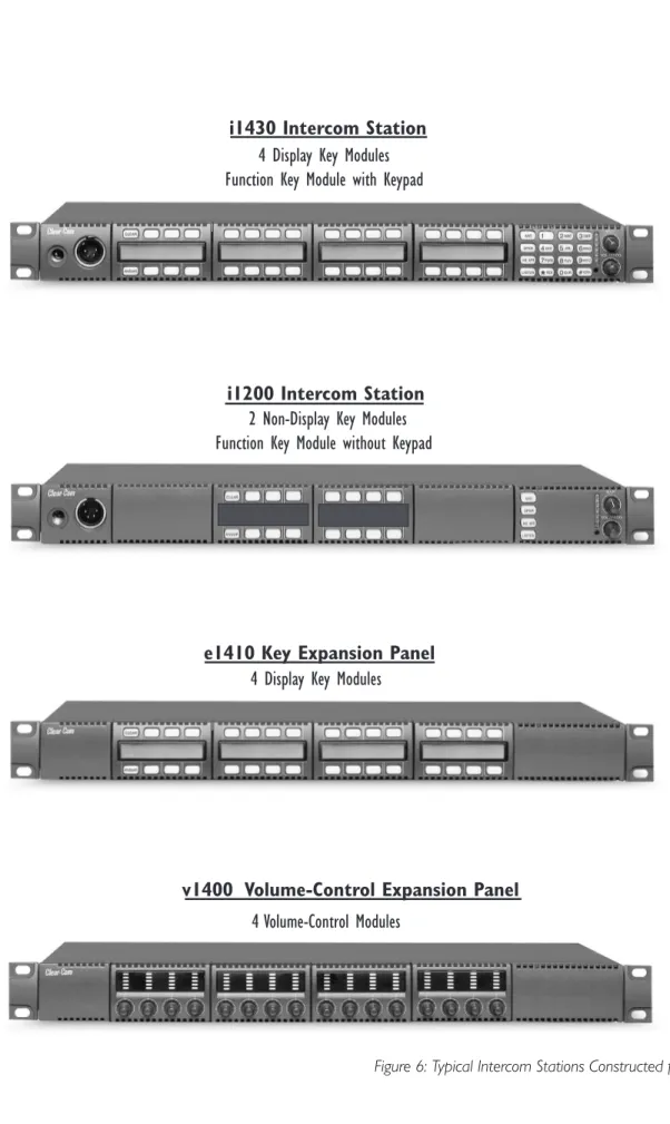
All i-series intercom stations are constructed of selected combinations of the front- and rear-panel modules. There are a total of eleven front-panel modules and two rear-panel modules in the i-series. Figure 5 on page 1-5 shows you the eleven front-panel modules. Figure 6 on page 1-6 shows you some typical i-stations formed from the basic modules.
The auxiliary options module connects your i-station to a variety of audio and control functions.
FUNCTION KEY MODULES
MIC-HEADSET MODULES
LEVEL-CONTROL MODULE
+Cams +Cams Phone Dir IFB−1 IFB−3 IFB−2 PGM Phone Dir IFB−1 IFB−3 IFB−2 PGM CLEAR ANSWR CLEAR ANSWR JKL 5 HS MIC SPKR ON LISTEN
*
RED PQRS 7 CLR 0 TUV 8 GN MIC 4GHI 1 2ABC VOL / PROG GRN # WXYZ 9 6MNO DEF 3 M A I N HS MIC SPKR ON LISTEN GN MIC VOL / PROG M A I NBlank Function Key Module Display Key Module
Display Key Module with Clear and Answer Keys
Non-Display Key Module with Clear and Answer Keys
Non-Display Key Module Blank Key Module
Function Key Module with Keypad Function Key Module without Keypad
Mic-Headset Module Blank Mic-Headset Module Level-Control Module
Phone IFB−1 IFB−2 Dir IFB−3 Pgm +Cams Phone IFB−1 IFB−2 +Cams Dir IFB−3 Pgm
Figure 6: Typical Intercom Stations Constructed from Modules
i1430 Intercom Station
4 Display Key Modules
Function Key Module with Keypad
e1410 Key Expansion Panel
4 Display Key Modules
v1400 Volume-Control Expansion Panel
4 Volume-Control Modules
i1200 Intercom Station
2 Non-Display Key Modules
Function Key Module without Keypad
POWERING AN I-STATION
NON-DISPLAY KEY MODULE START-UP SEQUENCE
When a station with non-display key modules is connected to power, all keys on each key module will flash red, then green, and will revert to their programmed colors (red for talk or talk-with-listen; green for listen). If there is no
communication to the Matrix, the keys will flash red once per second until communication to the Matrix is established.
DISPLAY KEY MODULE START-UP SEQUENCE
When a station with display key modules is connected to power, each of the display modules will show the following message:
Clear-Com Vx.x.x@2000
“V.x.x.x” represents the firmware version of the panel. All keys will flash red, then green, and will show their programmed colors and labels if there is
communication to the Matrix.
If there is no communication to the Matrix, the display will show the message “No connection to Matrix.” The keys will then flash red once per second until communication to the Matrix is established.
FUNCTION KEY MODULE START-UP SEQUENCE
When an intercom station is connected to power, all of the keys on the function key module will flash red, then green, and will revert to their programmed colors if there is communication to the Matrix.
If there is no communication to the Matrix, the keys will be dark until communication is established.
FRONT PANEL CONTROLS AND LIGHTS
A NOTE ABOUT TERMINOLOGY
In this manual, the term “source” refers to a device—intercom station, interface, beltpack, or a variety of other devices—that sends audio to your intercom station. It represents a “listen” path to your station. The term “destination” refers to a device to which you send audio. It represents a “talk” path from your intercom station.
The names of these sources and destinations appear in the display of your intercom station and are called “labels.” A label is a 5-character alphanumeric name that identifies a source, destination, or control function accessed by your intercom station.
ABOUT DISPLAYS
The 5-character name, or “label,” that you assign to a key is displayed next to the key on the key module. The labels on the upper row refer to their corresponding upper-row keys and the labels on the lower row refer to their corresponding lower-row keys.
Figure 7: Key Module
Display stations have full-graphic LED-backlit displays that you program either from the station itself or from the PGM-WIN Configuration Program.
Non-display stations have metal grooves into which paper labels can be inserted. Paper labels can be printed from the PGM-WIN Configuration Program.
ABOUT KEYS
Each key on any key module can be assigned as a talk, a listen, or a talk-with-listen from the PGM-WIN Configuration Program. See the
PGM-WIN Configuration Program Manual for more information.
Temporary or Latched Action
When you press a key to talk or listen, the key can be switched on either temporarily or continuously.
When you switch a key on temporarily, it is active for the particular period of time you require. Press and hold the key down for the desired length of time needed to talk or listen, then release the key to return it to its non-active state. You will only be able to talk or listen while you press the key.
Continuous or “latched” action allows you to lock a key into place, so that you can talk or listen hands-free. Quickly tap a key to “latch” or “lock” it into place to talk or listen. The key will glow brightly to indicate that it is active. The key will remain latched until you tap it again to return it to its non-active state.
Active and Non-Active Keys
When you activate a key—that is, when you press or latch the key to talk or listen— the key becomes bright red or green. When you press or latch an assigned talk key, the key lights up bright red while you talk to the destination.
Keys Alphanumeric Key Names or "Labels" +Cams +Cams Phone Dir IFB−1 IFB−3 IFB−2 PGM
Active keys are bright red or green. Non-active keys are dim red or green. Keys that are not assigned are off, with no illumination.
When you press or latch an assigned listen key, the key lights up bright green while you listen to the source.
Otherwise, a key that is not active—that is, a key that is not being used to talk or listen— will be dimmed: dim red for a talk or talk-with-listen key; dim green for a listen key.
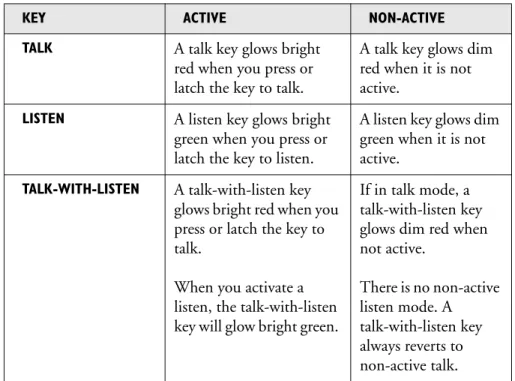
Table 1 shows the key colors associated with active or non-active talk, listen, or talk-with-listen keys.
Table 1: Key Colors for Active and Non-Active Keys
ABOUT LIGHTS
A key can be programmed to light up in a variety of ways to indicate its status. These options are discussed in the following sections. If you decide to use one of these options, it must usually first be set up in the PGM-WIN Configuration Program. A table summarizing all of the light options is located at the end of the section.
Call-Waiting Light
A key will flash rapidly (four times per second) when a source calls you. When you press the key to talk, the key becomes bright red to indicate that it is active. When you release the key, it becomes dim red to indicate that it is is not active, if the source is no longer sending audio.
If a key is active when a second source calls you, the key will not flash at the call-waiting rate, but will continue to glow solidly bright red to indicate that it is active. You will know another source is calling because you will hear their audio, the answer-back key will blink, and the source’s label will appear in the display
KEY ACTIVE NON-ACTIVE
TALK A talk key glows bright red when you press or latch the key to talk.
A talk key glows dim red when it is not active.
LISTEN A listen key glows bright green when you press or latch the key to listen.
A listen key glows dim green when it is not active.
TALK-WITH-LISTEN A talk-with-listen key glows bright red when you press or latch the key to talk.
When you activate a listen, the talk-with-listen key will glow bright green.
If in talk mode, a talk-with-listen key glows dim red when not active. There is no non-active listen mode. A talk-with-listen key always reverts to non-active talk.
above the answer-back key. You can answer the second source by pressing the answer-back key.
This option is set up by default in PGM-WIN, and it can be changed or cancelled if desired. Both the call-waiting light flash length and the amount of time the light flashes before the call is removed from the answer-back stack are programmable in PGM-WIN.
To configure the settings for this feature in PGM-WIN, choose Local Preferences from the Configure menu, then select Answer-Back Auto-Clear Time from the Option Description list. See the PGM-WIN Configuration Program Manual for
more information.
In-Use Light
A key will double-flash once per second to indicate that a destination you are trying to call is in use.
The in-use light is a feature that must be set up in the PGM-WIN Configuration Program. It is not the default option. To select the option, choose Global Advanced from the Configure menu, and click the box labeled In-Use Tally. For more information, see the PGM-WIN Configuration Program Manual.
Priority-Conflict Error Light
A priority conflict error occurs if you try to call a destination that is being accessed by another caller with a higher priority.
To indicate the priority conflict, your station’s speaker will beep twice and the destination’s key on your station will flash red rapidly when you press the key to talk. You will not be able to talk to the destination until the higher priority call has ended.
Telephone Off-Hook Light
A key will flash red once per second if a telephone interface is assigned to that key, and the telephone interface is off-hook. The central Matrix will cause each key assigned to the telephone interface on every station in the system to flash at the off-hook rate whenever the telephone interface is active (off-hook) at one or more of the stations.
If you press or latch a key that is flashing at the telephone off-hook rate, the key will glow solidly bright red to indicate that the key is active. When you release the key, it will resume flashing at the telephone off-hook rate.
This telephone off-hook light is set up by default in PGM-WIN, but it can be deactivated if necessary. To access the option settings in PGM-WIN, choose Applications from the Configure menu, and click the box labeled Telephone Off-Hook Tally. For more information, see the PGM-WIN Configuration Program Manual.
Radio-Receiver Active Light
The green light on a key will flash once per second if a radio receiver is assigned to that key, and the radio receiver is active. The central Matrix will cause each key assigned to the radio receiver on every station in the system to flash at the radio-receiver active rate whenever the radio receiver is active at one or more of the stations.
If you press or latch a key that is flashing at the radio- receiver active rate, the key will glow solidly bright green to indicate that the key is active. When you release the key, it will resume flashing at the radio-receiver active rate.
The radio-receiver active light is a feature that must be set up in the PGM-WIN Configuration Program. To select this option, choose Applications from the Configure menu, and click the box labeled Receiver Active Tally. For more information, see the PGM-WIN Configuration Program Manual.
Station-Connected Light
When the station-connected light option is selected in PGM-WIN, any time a destination station is connected to the Matrix frame, its assigned key on your station will flash red once per second. This option is primarily used when a destination station is connected to the Matrix frame via a long-line link (such as an ISDN or T1 link) that might be active only at certain times.
The station-connected light is a feature that must be set up in the PGM-WIN Configuration Program. It is not the default option. To select this option, choose Local Preferences from the Configure menu, and click Station Connected Tally in the Option Description list. For more information, see the PGM-WIN Configuration Program Manual.
Audio-Presence Light
If you assign a source to your station as a listen-only key, the key will flash green once per second if there is audio present at the source.
The audio-presence light is a feature that must be set up in the PGM-WIN Configuration Program. It is not the default option. To select this option, choose Local Preferences from the Configure menu, and click Enable Audio Presence Tally in the Option Description list. For more information, see the PGM-WIN Configuration Program Manual.
Incompatible Firmware Light
If the firmware on your station is incompatible with the Matrix, all lights on the station will blink bright red once per second, and if displays are present, they will read: “Firmware Version Incompatible.”
SUMMARY OF KEY MODULE LIGHTS
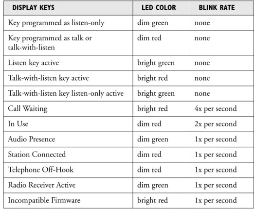
Table 2 summarizes the meaning of key colors and blink rates on a key module.
Table 2: Key Colors and Blink Rates
ANSWER-BACK FEATURE
With the answer-back feature you can reply to incoming calls from sources not assigned to keys on your intercom station. You can also call out to destinations not assigned to keys on your station.
If a second unassigned source calls you while you are speaking to the first unassigned source, the second call will be placed in the “answer-back stack,” a group of up to six waiting calls that are answered in sequence.
NOTE: All incoming calls can be answered at the answer-back key—whether from
sources with assigned keys on the intercom station or from sources without assigned keys. Typically, however, only calls from sources without assigned keys are answered there.
The following sections describe how to use the answer-back feature.
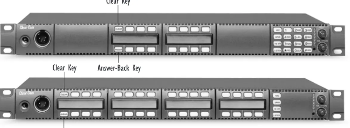
Answer-Back and Clear Keys
The answer-back key is the leftmost lower key on any intercom station. The clear key is the leftmost upper key on any intercom station. (See Figure 8.) The keys are labeled “ANSWR” and “CLEAR.”
DISPLAY KEYS LED COLOR BLINK RATE
Key programmed as listen-only dim green none Key programmed as talk or
talk-with-listen
dim red none Listen key active bright green none Talk-with-listen key active bright red none Talk-with-listen key listen-only active bright green none
Call Waiting bright red 4x per second
In Use dim red 2x per second
Audio Presence dim green 1x per second Station Connected dim red 1x per second Telephone Off-Hook dim red 1x per second Radio Receiver Active dim green 1x per second Incompatible Firmware bright red 1x per second
With the answer-back feature, you can reply to incoming calls from sources not assigned to keys on your station.
Figure 8: Answer-Back and Clear Keys
Answering a Call with the Answer-Back Key
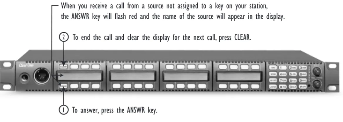
When a source that is not assigned to a key on your station calls you: • The calling source’s label appears in the display above the ANSWR key. • The ANSWR key flashes bright red to indicate a waiting call.
These conditions will continue until you press the ANSWR key to talk or until the answer-back time-out period lapses and the call is automatically removed from the answer-back stack.
NOTE: The answer-back time-out period is set in the PGM-WIN Configuration
Program. It can be set between 10 and 60 seconds. After the time-out period has elapsed, the call will be removed and will no longer be available to answer.
To answer a call from an unassigned source at the answer-back key:
1. Press the ANSWR key to talk to the caller.
When you press the ANSWR key, it becomes solid red to indicate that it is active. Note that the ANSWR key cannot be latched; it is a momentary function.
2. When you complete the call, release the ANSWR key.
When you release the key, it becomes dim red to indicate that it is inactive. 3. Press the CLEAR key to remove the caller’s label from the display.
• The display clears automatically when the answer-back time-out period elapses after you release the ANSWR key.
• See Figure 9 for an illustration of answering a call from an unassigned source at the answer-back key.
Answer-Back Key Clear Key
Clear Key
Answer-Back Key
You cannot latch an outgoing call from the answer-back key. This function is momentary only.
Figure 9: Answering a Call from an Unassigned Source at the Answer-Back Key
Answering a Second Call from the Answer-Back Stack
If a second unassigned source calls you while you are talking to the first unassigned source:
• The second caller’s audio will come through on your station’s speaker.
• The second call will be placed in the “answer-back stack” (a call list of up to six possible waiting calls). The second caller’s label will appear directly above the current caller’s label. The current caller’s label appears in the display directly above the ANSWR key.
• The light on the ANSWR key will flash to show that a call is waiting and that
a call is currently in progress—by flashing at the call-waiting rate to show that a call is waiting; but flashing bright red–dim red instead of the usual bright red–off to show that a call is also currently in progress.
To answer a call waiting in the answer-back stack:
1. Press the ANSWR key to speak to the caller.
The new caller’s label will appear in the position directly above the ANSWR key, while the next waiting call (if there is one) will display in the position directly above it. A total of six calls can wait in the answer-back stack. Only the two most recent caller’s labels will appear in the display above the ANSWR key.
2. When you complete the call, release the ANSWR key.
3. Press the CLEAR key to remove the caller’s label from the display.
• The next unassigned caller’s label appears in the display above the ANSWR key.
• The display clears automatically when the answer-back time-out period elapses after you release the ANSWR key.
4. When the next caller’s label appears above the ANSWR key, press the ANSWR key to talk to the caller.
5. Repeat steps 2 and 3 until all the calls in the answer-back stack are answered.
1 2
When you receive a call from a source not assigned to a key on your station, the ANSWR key will flash red and the name of the source will appear in the display.
To answer, press the ANSWR key.
To end the call and clear the display for the next call, press CLEAR.
When you press the ANSWR key, you will talk to the destination whose label is in the display. To clear the display, and talk to the next caller, press the CLEAR key.
Copying the Answer-Back’s Label to a Key’s Label on Your
Station
You can quickly copy the answer-back key’s talk assignment to another key on your station.
To copy the answer-back key’s assignment to a key on your station:
1. Press and continue to hold the “VOL/PROG” knob.
2. Tap or press the key to which you want to copy the answer-back key’s assignment.
• Tap the key lightly to assign it as a “talk” key to your station. • Press and hold the key for greater than 1/2 second to assign it as a
“talk-with-listen” key on your station.
This function copies the answer-back key’s assignment to the selected key on your station and clears the previous assignment.
SUMMARY OF ANSWER-BACK AND CLEAR KEY LIGHTS
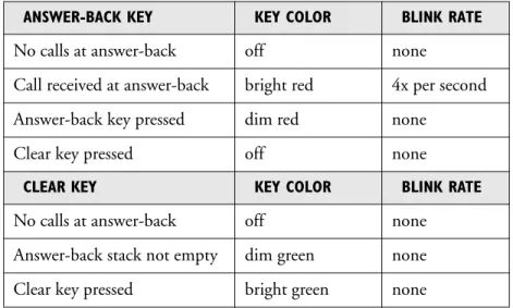
Table 3 summarizes the meanings of the color and blink rates for the answer-back and clear keys.
Table 3: Colors and Blink Rates for Answer-Back and Clear Keys
VOLUME CONTROLS
Speaker and Headset Volume Controls
Adjusting Intercom Volume
You adjust the master intercom volume on your station’s speaker and headset with the main volume knob on the function key module, as shown in Figure 10. Turn the knob clockwise to increase the volume, counterclockwise to decrease it.
ANSWER-BACK KEY KEY COLOR BLINK RATE
No calls at answer-back off none
Call received at answer-back bright red 4x per second Answer-back key pressed dim red none
Clear key pressed off none
CLEAR KEY KEY COLOR BLINK RATE
No calls at answer-back off none Answer-back stack not empty dim green none Clear key pressed bright green none
You can quickly copy the answer-back key’s talk assignment to another key on your station.
Figure 10: Main Volume and Program Volume Controls
Adjusting Program Input Volume
You receive program input at your station through the auxiliary options module, so this module must be present before you can adjust the program input. If you do not have the auxiliary options module installed on your station, the
VOL/PROG knob on the function keypad will not operate.
You adjust the program input volume on your station’s speaker and headset with the program volume knob, labeled “VOL/PROG” on the function key module. Turn the knob clockwise to increase the volume, counterclockwise to decrease it. The six LEDs located to the left of the program volume knob indicate the program volume level. As the volume goes up or down, the number of LEDs that are illuminated changes. Minimum volume is indicated by one illuminated LED; maximum volume is indicated by six illuminated LEDs.
You control the brightness of the six-segment LED with the Display Brightness settings in the PGM-WIN Configuration Program. Refer to the PGM-WIN Configuration Program Manual for more information.
Note: You can also use the program volume knob to adjust listen levels, to scroll
through menu items, and to select menu items. These functions are discussed later in this chapter.
Adjusting Listen Levels
When you need to monitor several incoming sources at once, you can vary the volume of the sources by setting “listen levels.”
For example, in a control room you may be listening simultaneously to the lighting department, the sound department, and the tape editing department, but because you need to cue the director when the show is ready to go on the air, listening to the tape editing department takes highest priority. You need to adjust the volumes of the monitored sources so that the tape editing department is louder than the others. To do this, you set listen levels.
There are two ways to adjust listen levels. One method requires using two hands, while the other method requires using only one hand. Both methods are described below. Main Volume Program Volume JKL 5 HS MIC SPKR ON LISTEN
*
RED PQRS 7 CLR 0 TUV 8 GN MIC 4GHI 1 2ABC VOL / PROG GRN # WXYZ 9 6MNO DEF 3 M A I NThe volume program knob is multi-functional. In addition to adjusting the program volume, it adjusts listen levels, scrolls through menu items, and selects menu items. These functions are discussed later in this chapter.
To adjust the listen level of an incoming source: Method 1 (Two-handed)
This method works with both the 4-button and 16-button function key modules.
1. Press and hold a listen key.
2. At the same time that you are pressing and holding the listen key in step 1, rotate the VOL/PROG knob either clockwise to increase the volume of the source or counterclockwise to decrease the volume of the source.
You will be able to hear the audio as you adjust it.
3. When you have completed adjusting the volume, release the listen key. The volume will remain at the level to which you have adjusted it. NOTE: If you try to push an active listen path higher than the maximum possible
volume, you will drive the volume of all other active paths downward, thus putting more emphasis on the desired path.
Figure 11: Adjusting Listen Levels: One-Handed Method
To adjust the listen level of an incoming source: Method 2 (One-handed)
This method works only with a 16-button function key module.
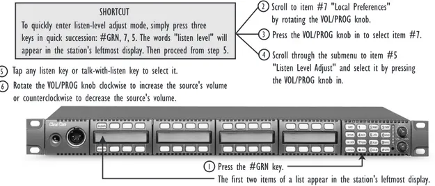
1. Press the ENTER key (labeled “#GRN”) on the numeric keypad to display a list of menu items.
The first two menu items appear in the station’s leftmost display. (For an illustration of this procedure, see Figure 11.)
2. Scroll to menu item number 7, “Local Preferences,” by rotating the VOL/PROG knob.
You can also scroll through the menu items one at a time by pressing the CLEAR key to scroll up the menu and the ANSWR key to scroll down the menu.
Press the #GRN key.
The first two items of a list appear in the station's leftmost display.
1
2 Scroll to item #7 "Local Preferences"
by rotating the VOL/PROG knob.
3 Press the VOL/PROG knob in to select item #7.
4 Scroll through the submenu to item #5 "Listen Level Adjust" and select it by pressing the VOL/PROG knob in.
5 Tap any listen key or talk-with-listen key to select it.
6 Rotate the VOL/PROG knob clockwise to increase the source's volume
or counterclockwise to decrease the source's volume. To quickly enter listen-level adjust mode, simply press three keys in quick succession: #GRN, 7, 5. The words "listen level" will appear in the station's leftmost display. Then proceed from step 5.
3. Select item 7 by pressing the VOL/PROG knob in, as if it were a key, when item 7 appears in the display.
• Another menu—a submenu—appears in the display.
• You can also select item number 7 simply by pressing the 7 key on the numeric keypad.
4. Scroll though the submenu to item number 5, “Listen Level Adjust,” and select it by pressing the VOL/PROG knob in, as if it were a key.
• The words “Listen Level” appear in the station’s leftmost display to indicate that you are in listen-level-adjust mode.
• You can also select submenu item number 5 simply by pressing the 5 key on the numeric keypad.
NOTE: To quickly enter listen-level-adjust mode, simply press three keys in quick
succession: the ENTER key (labeled “#GRN”), followed by the 5 key, followed by the 7 key. The words “Listen Level” will appear in the station’s leftmost display to indicate that you have entered the mode for adjusting listen levels. Then proceed forward from step 5 below.
5. Tap any listen key or talk-with-listen key to select it.
The key will glow bright green to indicate that you have selected it. 6. Rotate the VOL/PROG knob clockwise to increase the source’s volume or
counterclockwise to decrease the source’s volume.
7. Continue adjusting listen levels by first tapping a key to select it, and then rotating the VOL/PROG knob to adjust the source’s volume.
8. Press the ESCAPE key (labeled “*RED”) to exit listen-level-adjust mode. You can also exit listen-level-adjust mode by not pressing a key on the numeric keypad (0–9, *, #) for five seconds. After five seconds the mode times out.
Resetting Listen Levels to the Default Level
You can reset all listen levels to the default, which is the highest possible volume.
To reset all listen keys back to the default level.
1. Press the 7 key on the numeric keypad to enter Local Preferences mode. The display on the leftmost key module shows the first two items in a list of local preferences.
2. Scroll through the list by turning the VOL/PROG knob.
You can also scroll through the list one item at a time by pressing the CLEAR key to scroll up the list and the ANSWR key to scroll down the list.
3. When the menu item “Reset Listen Levels” appears in the display, select the item by pressing the VOL/PROG knob in, as if it were a key.
The display will read “Listen Level Reset Sent to Matrix.”
All listen keys are reset to the highest possible volume.When you activate a listen key at your station, audio will come in at that level. If a caller sends audio to you, that audio will come into your station at the highest possible volume.
For more information on local preferences, see “Local Preferences” under “Using the Advanced Function Keys” later in this chapter.
The VOL/PROG knob operates in two ways. You rotate the knob clockwise or counterclockwise to adjust volume levels or to scroll through menu items. You press the knob in, as if it were a key, to select items in a menu.
NOTE: The VOL/PROG knob operates in two ways. You rotate the knob to adjust
volume levels and to scroll through menu items. You press the knob in, as if it were a key, to select items in a menu.
USING THE BASIC FUNCTION KEYS
The following four basic function keys are located on the function key module: • GN MIC (gooseneck microphone on/off )
• HS MIC (headset microphone on/off ) • SPKR ON (speaker on/off )
• LISTEN (listen-only/call signal/remote telephone release)
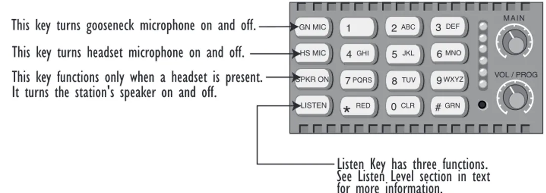
Figure 12 illustrates the location and purpose of the basic function keys. A more detailed discussion of each key follows.
Figure 12: Basic Function Keys
GN MIC (GOOSENECK MICROPHONE ON/OFF)
The gooseneck microphone key, labeled “GN MIC,” turns your station’s gooseneck microphone on or off. Press once to turn the microphone on; press again to turn the microphone off.
The gooseneck microphone is your station’s default microphone unless a headset is plugged in. When a headset is plugged in, an auto-sensing circuit in the station automatically turns the headset microphone on and turns the gooseneck
microphone off. The headset microphone always takes precedence over the gooseneck microphone.
If you press a talk key while the gooseneck microphone is plugged in but off, the gooseneck microphone automatically turns on for the duration of the call. The GN MIC key glows dim green whenever the gooseneck microphone is present but off and bright green whenever the microphone is present and on. If a gooseneck microphone is not present, the GN MIC key will not illuminate. Table 4 summarizes the key colors for active and non-active microphone and speaker keys.
This key turns gooseneck microphone on and off.
JKL 5 HS MIC SPKR ON LISTEN
*
RED PQRS 7 CLR 0 TUV 8 GN MIC 4GHI 1 2ABC VOL / PROG GRN # WXYZ 9 6MNO DEF 3 M A I NThis key turns headset microphone on and off. This key functions only when a headset is present. It turns the station's speaker on and off.
Listen Key has three functions. See Listen Level section in text for more information.
There are four basic function keys.
HS MIC (HEADSET MICROPHONE ON/OFF)
The headset microphone key, labeled “HS MIC,” turns your station’s headset microphone on and off. Press once to turn the microphone on; press again to turn the microphone off.
When a headset is plugged in to the station, the headset microphone
automatically becomes active and the gooseneck microphone is switched off. To switch to the gooseneck microphone, press the gooseneck microphone key, labeled “GN MIC.” When the headset is unplugged, the gooseneck microphone automatically becomes active.
The HS MIC key glows dim green whenever a headset microphone is present but off, and bright green whenever a headset microphone is present and on. When a headset microphone is not present, the key will not illuminate. Table 4 on page 1-22 summarizes the key colors for active and non-active microphone and speaker keys.
SPKR ON (SPEAKER ON/OFF)
The speaker on/off key, labeled “SPKR ON,” functions only when a headset is plugged into the station. Pressing the speaker on/off key toggles the headset speaker on and off. Press the key once to turn the headset speaker off, and again to turn the headset speaker back on. As the headset speaker turns off, the panel speaker will turn on and vice versa.
The key glows dim green whenever the headset speaker is off, and bright green whenever the headset speaker is on.
NOTE: Unlike the microphones, both speakers can never be turned off at the same
time. The panel loudspeaker is always active unless a headset or alternative speaker source has replaced it. That is why this key is non-functional when a headset is not plugged in.
LISTEN (LISTEN-ONLY/CALL SIGNAL/REMOTE TELEPHONE LINE RELEASE)
The LISTEN key has three functions:• Activates the “monitor mode” of a “talk-with-listen” key • Sends call signals
• Releases remote telephone lines
Figure 13 summarizes how to access these functions from the LISTEN key. The sections that follow discuss the functions in detail.
Figure 13: Accessing Features from the Listen Key
Activating the “Monitor Mode” of a Talk-with-Listen Key
NOTE: To avoid confusion, in this manual the LISTEN key on the function-key
module is referred to in all capital letters. On your i-station “LISTEN” is printed on this key in all capital letters as well. Keys on your station programmed to “listen” are referred to in this manual in lower-case letters, as in “the listen key glows bright green.”
The i-station “monitor mode” allows you to momentarily change the status of a key from listen-only to talk-with-listen. By pressing and holding the listen-only key, you momentarily change it to a talk-with-listen key.
Figure 14: Activating the “Monitor Mode” of a Talk-with-Listen Key
1
2
To activate the "listen" function of a "talk-with-listen" key, press the LISTEN key less than five seconds ("tap" the key) and then tap the desired "talk-with-listen" key. The LISTEN key illuminates bright green.
To send a call signal, press the LISTEN key for between 1 and 5 seconds and then press the key of the destination that you want to send the call signal to. The LISTEN key illuminates bright red.
To release a remote telephone line, press the LISTEN key for 5 seconds and continue to hold while you press the desired telephone interface key. The LISTEN key turns dim red and flashes on and off.
3
MONITOR MODE
CALL SIGNAL
RELEASE A REMOTE TELEPHONE LINE
1 3
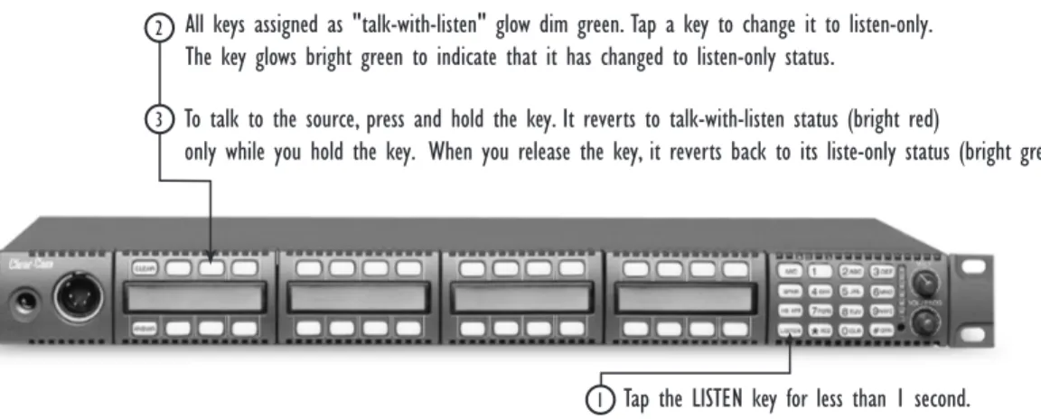
Tap the LISTEN key for less than 1 second.
2 All keys assigned as "talk-with-listen" glow dim green. Tap a key to change it to listen-only.
The key glows bright green to indicate that it has changed to listen-only status.
To talk to the source, press and hold the key. It reverts to talk-with-listen status (bright red)
To activate the “monitor mode” of a talk-with-listen key:
1. Press the LISTEN key on the function key module for less than one second (“tap” the key).
• Each key assigned as a talk-with-listen glows dim green to indicate that its “monitor mode” is available for activation.
• The LISTEN key on the function key module glows bright green while in this mode.
2. Tap a dim-green key to activate it.
The key glows bright green to indicate its change to an active listen-only key. 3. To talk to the source, press and hold the key.
The key glows bright red to indicate that a talk-with-listen call is active. When you release the key, it reverts back to its active listen-only mode (bright green). The talk-with-listen function cannot be latched; it is only active while you press the key.
To cancel the key’s monitor mode and revert back to the talk-with-listen mode:
1. Tap the LISTEN key on the function-key module. 2. Tap the desired active listen-only key (bright green).
The formerly active listen-only key now glows dim red to indicate that it has reverted back to its non-active talk-with-listen mode. If you press the key to talk, it glows bright red.
NOTE: You must tap the LISTEN key on the function key module for each key you
activate in “monitor mode.”
Sending Call Signals
A call signal is an electronic signal that is sent from one station or interface to another to get a station operator’s attention. It can be used for a variety of more technical purposes as well, such as to activate a relay to open a door, set off an alarm, or activate a public address (PA) system.
To send a call signal:
1. Press and hold the LISTEN key for between 1 and 5 seconds. The LISTEN key turns bright red to indicate that you have entered the “call-signal send” mode.
2. Press the key of the destination that you want to send the call signal to. A call signal of three loud beeps is sent to a destination each time that you press the destination’s key.
3. To send a call signal to a new destination, press the new destination’s key. A call signal is sent to the new destination each time you press that destination’s key.
4. To exit “call-signal send” mode, tap the LISTEN key and release.
• You can also exit “call-signal send” mode by simply not pressing a display key for five seconds. The mode will automatically time-out.
You can scroll one item at a time through items in a displayed list by pressing the CLEAR key to scroll up the list and the ANSWR key to scroll down the list.
• When you exit “call-signal send” mode, the LISTEN key changes from bright red to no illumination.
You can send a call signal to any destination with a designated key on your station. If more than one destination is assigned to a key, each destination will receive the call signal. If the destination is a party line, then every station listening on the party line will receive the call signal.
NOTE: The call signal is sent at the page-override volume level, which is
programmable in the PGM-WIN Configuration Program. For more information, see the PGM-WIN Configuration Program Manual .
Releasing Remote Telephone Lines
To release a telephone interface that has been left off-hook:
1. Enable “remote telephone release” for that station in the PGM-WIN Configuration Program.
Often this feature will already be set up in the Configuration Program. For more information, refer to the PGM-WIN Configuration Program Manual.
2. Press and hold the LISTEN key for more than 5 seconds. The LISTEN key turns bright green and flashes on and off.
3. While still holding the LISTEN key, press the desired telephone interface key on any key module.
The telephone interface will hang up. All audio paths to and from the telephone interface will be deactivated.
4. Release the LISTEN key to exit.
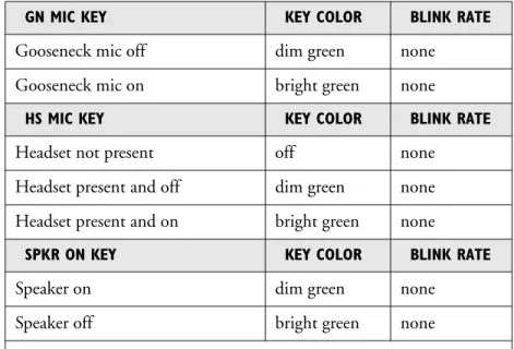
SUMMARY OF FUNCTION KEY MODULE LIGHTS
Table 4 summarizes the meanings of the colors and blink rates for all the keys on the function key module.
GN MIC KEY KEY COLOR BLINK RATE
Gooseneck mic off dim green none Gooseneck mic on bright green none
HS MIC KEY KEY COLOR BLINK RATE
Headset not present off none Headset present and off dim green none Headset present and on bright green none
SPKR ON KEY KEY COLOR BLINK RATE
Speaker on dim green none Speaker off bright green none
Table 4: Colors and Blink Rates for Keys on Function Key Module
USING THE ADVANCED FUNCTION KEYS
You can access additional features with the 12 keys on the function keypad module’s numeric keypad (0–9, *, #) or fom the station’s feature menu. You access a feature in one of two ways:
• By pressing the number key associated with the feature. For example, when you press the “1” key on the numeric keypad, you enter “telephone dialing” mode. Figure 15 shows the features associated with each number key on the numeric keypad. A fuller discussion of each feature follows.
• By scrolling through the feature menu. For example, you can scroll through the feature menu, and select “dial” to access the “telephone dialing” mode. The advantage of a menu is that you do not have to memorize each available key function. See “Selecting Features from the Menu” later in this section for more information.
Most of the features are available only when a station is connected to the Matrix, but some are available even when a station is not connected to the Matrix. (The requirements for each feature are given in the following sections.) Figure 15 and Table 5 below list features and identify which number keys on the keypad are associated with each.
LISTEN KEY KEY COLOR BLINK RATE
No function off none
Listen-only call mode bright green none Call-signal send mode bright red none
Remote telephone hang-up bright green 1x per second
0–9, *, # KEYS KEY COLOR BLINK RATE
No function off none
Key pressed or mode active bright green none
Dial mode dim red none
Dial mode and key pressed bright red none
You access the advanced features from the function module’s numeric keypad or from the feature menu.
Figure 15: Features Accessed by Keys on the Numeric Keypad
SUMMARY OF ADVANCED FEATURES
KEY FUNCTION DESCRIPTION
1 Dial Enters telephone dialing mode.
2 Local Exclusive Enters mode to temporarily deactivate all keys except the one being used.
3 Local Page Override
Enters mode to override current on/off and volume settings at a destination.
4 Assignment Panel
Enters mode to use assignment panel.
5 Pick List Scroll Enters mode to assign sources and destinations in the system to keys on your station.
6 N/A Not used.
7 Local Preferences Enters mode to adjust various volume levels on the station including: gooseneck mic volume, headset mic volume, sidetone, and listen levels.
8 Station Information
Gives you front-panel module position
numbers, version numbers, and copyright dates.
9 Port Information Gives you the station’s port number and label at the central Matrix and the station’s current firmware version number.
0 CLR Clear Clears the current display entry and takes you back to the previous menu.
* RED Escape or Cancel Abandons all unsaved programming and returns the station to normal use.
JKL 5 HS MIC SPKR ON LISTEN
*
RED PQRS 7 CLR 0 TUV 8 GN MIC 4GHI 1 2ABC VOL / PROG GRN # WXYZ 9 6MNO DEF 3 M A I N 1 7 # 9 8*
0 2 4 5 3 6 Dial Local ExclusiveLocal Page Override Assignment Panel
Pick List Scroll N/A Local Preferences Station Information Port Information Escape or Cancel Clear Enter
Table 5: Advanced Key Functions
DTMF DIALING FROM THE KEYPAD (#1 KEY)
You can dial from the keypad on a function key module as if you were dialing from a standard telephone keypad. When you press the number keys, standard DTMF tones are generated to all active talk key destinations. Note that this feature is only available when the Matrix is connected and online.
Figure 16: Telephone Dialing from the Function Keypad Module
To generate standard DTMF tones to all active talk key destinations:
1. Press the “1” key on the keypad to enter dialing mode. • The keypad becomes a telephone touch-tone dialing pad. • The word “dial” appears in the display below the CLEAR key. • All 12 valid dialing keys on the keypad glow dim red.
2. Press keys on the numeric keypad (0–9, *, #) to generate standard DTMF tones to all active talk-key destinations.
3. Press the CLEAR key to exit dialing mode.
Dialing mode automatically times out if you do not press a key on the numeric keypad (0–9, *, #) for five seconds.
# GRN Enter Saves the current programming changes and reverts the station to normal use.
VOL/PROG KNOB Display Contrast Adjust Baud Rate Adjust
Allows you to adjust contrast lighting on displays and to adjust the station’s baud rate
KEY FUNCTION DESCRIPTION
1a
1b 2
Press the "1" key on the numeric keypad to enter dialing mode. When you complete step 1,
the word "dial" appears in the display.
Press keys on the numeric keypad to generate DTMF tones to all active talk key destinations.
LOCAL EXCLUSIVE (#2 KEY)
When you activate the “local exclusive” feature, all previously latched keys on your station deactivate temporarily while you either talk to one destination or listen to one source. Note that the “local exclusive” feature is only active when the Matrix is connected and online.
To activate the local exclusive function:
1. Press the “2” key on the keypad to enter “local exclusive” mode. 2. Press any talk or listen key (even an already latched key).
• When you press a talk or listen key, all previously latched keys (both talks and listens) deactivate temporarily, and you can talk or listen from that key exclusively.
• The feature is only active while you press the key–it cannot be latched. • The “2” key on the keypad will glow bright green while this feature is
active.
3. To exit “local exclusive,” release the key you pressed in step 2. • The previously latched keys will return to their active state. • You can also exit this feature by not pressing a key for five seconds. • This feature does not work on the answer-back (ANSWR) key.
You can also select this feature from the menu. See “Accessing Feature Menus” later in this chapter for more information.
LOCAL PAGE OVERRIDE (#3 KEY)
The “local page override” feature allows you to talk to one or more destination stations regardless of the on/off or volume settings at each station’s speaker. The feature literally “overrides” the current on/off and volume settings at the destination.
You can adjust the local page override’s volume level in the PGM-WIN Configuration Program. By default, the volume is set up at 5 on a 1–10 scale, but it can be adjusted to any value on the scale.
Note that this feature is only active when the Matrix is connected and online.
To activate local page override:
1. Press “3” on the keypad to enter “local page override” mode. 2. Press any talk key (even an already latched key).
• You can talk to all destinations associated with that key. The current on/off settings and volume levels will be overridden at those stations’ speakers. • The “3” key on the keypad will glow bright green while this feature is
active.
• Local page override does not work from the answer-back (ANSWR) key.
To select an item with the VOL/PROG knob, press the knob in, as you would press a key, when the desired item appears in the display.
3. To exit “local page override,” release the pressed talk key.
Local page override mode automatically times out if you do not press a key on the function-key module for five seconds.
You can also enter the “local page override” mode by selecting it from the feature menu. See “Accessing Feature Menus” later in this chapter for more information. Note that if a key cannot be page overridden because it is assigned as an interface or party line, there will not be an error message to indicate that the function is not available on that key.
ASSIGNMENT PANEL (#4 KEY)
With your i-station or i-station expansion panel, you can assign an external audio source, often called a “program” source, to a destination. Typically this function is used to route “on-the-air” audio to the “talent” or announcer in a television studio application, but it can have many other uses as well.
You must set up this function in the PGM-WIN Configuration Program before you can use the i-station or the i-station expansion panel to assign external audio sources to destinations.
Note that this feature is only active when the Matrix is connected and online.
To choose assignment panel function in the PGM-WIN Configuration Pro-gram:
1. From the Configure menu, select Local Preferences.
The Configure dialog box opens, with the Local Preferences tab selected. 2. In the leftmost upper area of the dialog box, select the Stations option.
A list of stations in the intercom system appears. 3. Click the desired station.
A list of possible options for the stations appears in the Option Description area.
4. In the Option Description area, click either:
• Enable AP Function When you select this option both the intercom station and its connected expansion panel will become assignment panels.
• AP Function on Expansion Panel Only When you select this option only the expansion panel will become an assignment panel. Its connected intercom station will function as usual. 5. Click OK.
Your i-series intercom station and/or expansion panel now functions as an assignment panel. The following section describes the procedure for assigning a destination to a source from the assignment panel.
To assign a destination to a source from the i-station or expansion panel:
1. Press “4” on the i-station’s numeric keypad.
All sources blink green and all destinations blink red. The words “IFB Enter” appear in the station’s leftmost display.
2. Press a destination’s key on your station to select it. The selected destination’s key glows solid red. 3. Press a source’s key on your station to select it.
• The selected source’s key glows solid green.
• To select more than one source you must check the “Assign multiple sources to IFB from AP Panel” option on the System Preferences dialog box in the PGM-WIN Configuration Program. For more information, see the
PGM-WIN Configuration Program Instruction Manual.
4. Press Enter or Return.
The selected source or sources of program audio are assigned to the selected destination.
Although you can select more than one source of program audio, you can select only one destination.
PICK LIST SCROLL (#5 KEY)
The “pick list scroll” feature allows you to assign any intercom station or interface in the system to a key on your station directly from your station. You can assign the station or interface to your station as a talk key, a listen key, or a
talk-with-listen key.
To do this, you first access a list of all stations and interfaces in the system on the front-panel display of your i-station. You then scroll through the list and select the station or interface that you want to assign to your station. In other words, you literally “pick” from a “list” that you “scroll” through. This feature is only available when the Matrix is connected and online.
Two procedures are described below. The first describes how to assign a remote destination to your station as a “talk” or “talk-with-listen” key. The second describes how to asssign a remote source to your station as a “listen” key.
Figure 17: Assigning a Remote Destination to a Talk or Talk-with-Listen Key
1
2 3
Press the "5" key on the numeric keypad. A list of current destinations in the system appears
in the leftmost display on the station. Scroll through the list. See the procedure for more information.
When the desired destination appears in the display, select it by pressing the VOL/PROG knob in, as if it were a key.
4 Assign the selected remote station or interface to a key on your
station by tapping the desired key for less than 1/2 second to assign it as a "talk" or for more than 1/2 second to assign it as a "talk-with-listen."