warwick.ac.uk/lib-publications
Manuscript version: Author’s Accepted Manuscript
The version presented in WRAP is the author’s accepted manuscript and may differ from the
published version or Version of Record.
Persistent WRAP URL:
http://wrap.warwick.ac.uk/111792
How to cite:
Please refer to published version for the most recent bibliographic citation information.
If a published version is known of, the repository item page linked to above, will contain
details on accessing it.
Copyright and reuse:
The Warwick Research Archive Portal (WRAP) makes this work by researchers of the
University of Warwick available open access under the following conditions.
Copyright © and all moral rights to the version of the paper presented here belong to the
individual author(s) and/or other copyright owners. To the extent reasonable and
practicable the material made available in WRAP has been checked for eligibility before
being made available.
Copies of full items can be used for personal research or study, educational, or not-for-profit
purposes without prior permission or charge. Provided that the authors, title and full
bibliographic details are credited, a hyperlink and/or URL is given for the original metadata
page and the content is not changed in any way.
Publisher’s statement:
Please refer to the repository item page, publisher’s statement section, for further
information.
Towards High Capacity Molecular Communications
using Sequential Vortex Rings
Mahmoud Abbaszadeh
1, Peter J. Thomas
1, Weisi Guo
1*Abstract—Molecular signal coherence in fluid dynamic chan-nels is severely hindered by mass, momentum, and turbulent diffusive forces. The combination of such forces causes long molecular tails, which results in severe inter-symbol-interference (ISI) and limits the achievable symbol rate. Here, we propose to modulate information symbols into stable vortex ring structures to minimize ISI. Each vortex ring can propagate approximately
100× the diameter of the transmission nozzle without losing its compact shape. First, we show that the ISI from sequential transmissions is minimal and reduces rapidly with distance after transmission. This is the opposite effect to conventional molecular puffs undergoing advection-diffusion, whereby ISI increases with distance. Second, we show that by maintaining a coherent signal structure, the signal-to-inference (SIR) ratio is 211× higher over conventional puffs. Also, we demonstrate the vortex ring using a proof-of-concept prototype. The results point towards a promising pathway for higher capacity channels.
I. INTRODUCTION
Conventional molecular signals are represented by discon-tinuous molecular puffs that are ejected into a fluid or gas channel. After ejection, at the macro-scale, the signal is subject to various pressure, velocity, sheer stress gradients, as well as reaction forces. The coupling relationships between these forces and the flow rate are well described by the Navier-Stokes (NS) equations [1]. Existing literature in molecular communications has predominantly used isotropic diffusion-advection channel models due to their tractable expressions [2], assuming a P´eclet number below 1 (e.g. mass diffusion dominates). Whilst this is reasonable for cell membranes and capillary blood flow, advection and external forces will dominate at larger-scales. Sheer stress between laminar flow layers leads to viscous momentum diffusion and turbulence will cause turbulent diffusion [3].
A. Vortex Rings in Turbulence
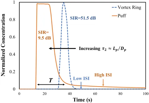
Turbulence is not only inherently very difficult to model, but it also doesn’t directly help us understand the communication capacity of the channel. Yet, we can take advantage of a certain structure called a vortex ring, that propagates well in turbulent fluid channels. The vortex ring retains spatial structure through its rotational momentum and has a sharper concentration time profile than a standard puff - see Fig.1. This has the potential to significantly reduce inter-symbol-interference (ISI) from sequential transmissions and as such allow us to transmit at a higher symbol rate. The vortex
1School of Engineering, University of Warwick. *Corresponding Author: [email protected]. This work is funded by the US AFOSR grant FA9550-17-1-0056.
0 0.2 0.4 0.6 0.8 1
0 20 40 60 80 100
No
rma
li
ze
d
Co
nc
ent
ra
ti
on
Time (s)
Vortex Ring Puff
SIR= 9.5 dB
SIR=51.5 dB
Increasing
High ISI
T
!"≈%&⁄'&
[image:2.612.320.559.178.344.2]Low ISI
Fig. 1. Concentration (normalised) time profile at receiver for a standard puff (large ISI) and a vortex ring (small ISI).
ring core is a torus shaped fluid or gas structure, that retains shape (e.g. mitigates dispersion) for long propagation distances (typically50×nozzlediameter) [4] - see Fig.2. Each vortex ring is a region, where the molecules mostly spin around an axis in a closed loop. Finally, it should be noted that one of the possible application of the vortex rings is the Line-of-sight (LOS) communication.
B. Contribution
In this letters, we will use both simulation and experimen-tation to outline how vortex rings are generated and how they effectively mitigate ISI over long distances. In Section II, we present the theoretical structure of a vortex ring and the transmitter design required to generate it. In Section IV, we show the propagation life cycle of sequential vortex rings in comparison to conventional molecule puffs and demonstrate it using an experimental proof-of-concept test-bed. We analyze the SIR profile for different configuration parameters and discuss capacity scalability potential. Finally, we observe the effects of the each vortex ring on the others in a sequential vortex rings and the way they can go through the channel with the minimum interference.
II. VORTEXRINGSTRUCTURE& GENERATION
Z X Y θ O D/2 δ/2 Г Vortex Ring Core Vortex Atmosphere 𝑈𝑝
𝐷0 𝑫 𝟐Τ
𝜃 𝚭 𝐿0 Vortex Atmosphere Vortex Ring Core 𝐷𝑃 𝑈0
Piston
a b
𝐿𝑃
Fig. 2. (a) Illustration of transmitter piston design to generate vortex ring. (b) Illustration of vortex ring core properties and its orientation in cylindrical coordinates with a surrounding vortex atmosphere.
that the vortex core can become wavy (Widnall instability) at some point during its existence depending on conditions. The general properties of every vortex ring can be observed in Fig.2, where the vortex ring core has diameter of D
(approximately 1.3× the nozzle diameter D0) and the bulk
of vorticity in the region has diameter of δ. There is also a small atmosphere surrounding the core - see Fig.2b.
In order to design the transmitter that can generate a vortex ring, careful consideration is needed - see Fig.2a. First, the molecules inside the piston must be subject to a sufficient sheer stress profile such that vortices are generated. This occurs when the molecules are pushed out at a sufficiently high Reynolds number, generating a vortex ring head. In the case of vortex rings, the Reynolds number is given by ReΓ = Γν
whereν is the kinematic viscosity of the ejected fluid and Γ
is the circulation given in Eq.1. To find ReΓ, we first need
to define the inertial forces inside a region of vorticity, with molecules spinning around an imaginary axis in a closed loop.
Γ = Z
S
∇ ×udS= I
l
udl, (1)
whereSis a closed surface which is bounded by linelandu
is the velocity field in the flow domain.
To generate the vortex ring, a prescribed axial velocity can be defined at the transmitter to simulate the motion of the piston and also to define the vorticities at the edge of the piston [6]:
Vz(t, r) =V0(t)Vzb(r), (2)
whereV0(t)is the time-variant velocity program that expresses
the piston motion and given by [6]:
V0(t) =
Up 2
1 + tanhh5
τ1(t−τ1)
i
, t < τ1+τ22
Up
2
1 + tanhhτ5
1(τ1+τ2−t)
i
, t≥τ1+τ22
(3) where Up is the maximum piston velocity. Parameter τ1 is
a short-time acceleration/deceleration of the impulsive piston, and the value of theτ2is equal to stroke ratio (τ2≈Lp/DP).
In the stroke ratio formula, Lp is the stroke length, and if the
0 0.4 0.8 1.2
-0.25 0.15 0.55 0.95
r
Vz
[image:3.612.79.538.57.203.2]Present Study Danaila and Helie [6]
Fig. 3. Validation of present study with Danaila and Helie’s study [6].
piston reaches to the end of the cylinder, we have maximum stroke ratio as shown in Fig.2a.
Also, Vzb is the classical hyperbolic tangent profile which
has been derived from the experiment and represents the thickness of vorticity layer at the edge of the cylinder [7]:
Vzb(r) =
1 2
1 + tanh
1 2δw
Dp
2r −
2r Dp ! , (4)
whereδw is the dimensionless thickness of vorticity layer at
the transmitter and it is considered 0.05 in the present study which shows a thin vorticity layer. The diameter of piston is
Dp andr is the radial distance from the center of inlet.
The only theoretical insight comes from the piston stroke ratio. For Lp/Dp≥4, the leading vortex ring is followed
by an active trailing jet-like region [8], and as the stroke ratio increases, more ejected fluid stay behind the leading vortex ring. Actually, the maximum circulation that a vortex ring can attain, occurs at Lp/Dp ≈ 4 (which is refer as “formation
number”) [8] and after that, as the stroke ratio increases, the leading vortex ring sheds excessive ejected fluid behind. Also, all the quantities in the present study are normalized by Dp
andUp as the characteristic length and velocity, respectively.
Also,Dp/Up is used to normalize the time.
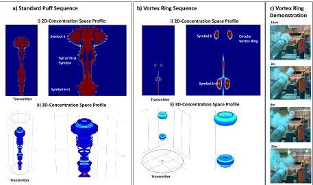
[image:3.612.324.546.259.409.2]a) Standard Puff Sequence b) Vortex Ring Sequence
i) 2D-Concentration Space Profile
ii) 3D-Concentration Space Profile
i) 2D-Concentration Space Profile
ii) 3D-Concentration Space Profile
c) Vortex Ring Demonstration
15cm
3m
8m
20m
Transmitter
Transmitter Transmitter
Transmitter
Symbol k Circular Vortex Ring
Symbol k+1 Symbol k
[image:4.612.79.536.62.332.2]Symbol k+1 Tail of First Symbol
Fig. 4. Sequential symbols transmitted: (a) Puffs, (b) Vortex Rings, and (c) Experimentation of Vortex Rings.
TABLE I SIMULATIONPARAMETERS
Variable Value
Stroke Ratio,Lp/Dp 2 - vortex ring, 14 - Puff Maximum Injection Velocity,UP 2.5 m/s at t= 0
Dynamic Viscosity of water,ν 8.9×10⁻⁴ Pa.s Transmit Concentration,c0 2.5 mol/m3
Pulse Width,T0 2.29 s
Symbol Period,T 16 s
Simulation Space 50Dp long,20Dpwide
program, we simulate the Danaila and Helie’s [6] injector and present the results in Fig.3 where a good agreement can be observed between our results and Danaila and Helie’s [6] study. In this figure, ris the normalized radial distance from the center of piston outlet and Vz is the normalized axial
velocity.
III. RESULTS& DISCUSSION A. Method and Parameters
In order to fully model turbulent diffusion with an anisotropic and time-varying velocity profile, the
Reynolds-averaged Navier-Stokes (RANS)equations needs to be
con-sidered [3]:
cuj
∂ui
∂xj
=cfi+ ∂
∂xj
−pδij+µ
∂ui
∂xj
+∂uj
∂xi
−cu0iu0j
.
(5) wherecrepresents density or concentration which depends on a number of pressure, velocity, and sheer stress gradients. .
represents time-averaged value, and µ is dynamic viscosity of the fluid. The cuj∂u∂xi
j represents the change in mean
momentum of fluid element owing to the unsteadiness in the mean flow and the convection by the mean flow. This is balanced by the mean body force fi, the isotropic stress from the pressure fieldpδij, the viscous stresses, and apparent
stress−cu0iu0jowing to the fluctuating velocity field (Reynolds stress). Whilst there are statistical approximate solutions in the form of eddy diffusivity, general tractability is still a challenge for modeling turbulent diffusion processes. This is the reason why finite-element simulation and experimentation is used.
B. Transmission
1) Simulation: The simulations are conducted using in-dustrial standard COMSOL software with the Computational Fluid Dynamics (CFD) and Chemical Species Transport mod-ules coupled. The simulation parameters are given in Table I. We shoot a sequence of conventional puffs and vortex rings and show their forward concentration (space domain) profiles in Fig.4. Each received signal is given by:c(t) =PK
k akh(t−
kT), wherea is 1 or 0 (OOK), T is the symbol period, and the channelh(.)is a complex fluid dynamic channel described by the aforementioned RANS equations to solve for the turbulence effects. In reality and for detection purposes, we can employparticle image velocimetry (PIV) and planar laser
induced florescence (PLIF) techniques which is a passive
an active way of detection. Both of the aforementioned ways, recover the spatio-temporal profiles.
It is worth noting that under RANS, these are the averaged profiles over a small simulation element. We assume that the vortex rings are sufficiently separated such that each behaves independently, but will explore mutual interactions in the future, especially the effects of leap-frogging and the leading vortex ring’s drag.
Puff Sequence - Fig.4a-i shows the concentration profile,
where there is a rapid deterioration in concentration structure and intensity over distance. As such, the tail from prior symbols leads to strong ISI. Fig.4a-ii is the 3D concentration profile and reveals that there is not a specific circular ring in the environment and the tail of the puff remains in the environment for a whole period of transmission.
Vortex Ring Sequence - The results in Fig.4b-i show that
the vortex ring core has a high concentration compared to the quiescence environment and maintains this into distance. This means that the vortex ring is carrying the momentum of the transmitter and is dominant in the way it propagates through the environment. Fig.4b-ii shows the concentration profile in three dimensional, where high concentration is maintained and the ISI effects are small. Overall, we observe that the ISI tail is significantly lower for the vortex ring (as shown in the concentration time profile in Fig.1).
2) Experimentation: We also present a proof-of-concept demonstration of the vortex ring, being shot 20m into an uncontrolled environment in Fig.4c. We have a 0.5m diameter vortex canon that is shooting a vortex ring captured on a slow motion camera. The red rings label the location of the vortex ring as it propagates away from the canon. The vortex ring becomes clearer as it moves into the distance.
C. Signal-to-Interference (SIR) Ratio
For the received signal with empirical response h(t), we define the signal S = RT
0 h(t) dt as the aggregate peak
concentration values detected over symbol periodT. We define the ISI as I = P
k
RT
0 h(t+kT) dt =
R+∞
T h(t) dt as the
remaining tail concentration t > T. For a single symbol, the resulting SIR is as follows - see Fig.1: (1) Vortex Ring: +51.5dB, and (2) Puff: +9.5dB. We can see approximately a
211×improvement when the vortex ring is compared to the puff. As shown in Fig.5, we can see that SIR as a function of transmission distance for a standard puff (SIR decays with distance) and a vortex ring (SIR increases with distance).
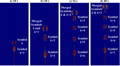
D. Sequential Vortex Rings
In this section, we transmitted eight vortex rings in order to observe the effects of the each vortex ring on the others and to see how a sequence of information can be carried by vortex rings with minimum interference and maximum symbol rate. Parameters:Up=5 m/s and theLp/Dp= 1. The vortex rings
concentration profiles are displayed in Fig.6 at four different time snapshots after transmission. After 10s (Fig.6-a), we can see that the second vortex ringk+ 1catches up to the firstk, due to the lower drag forced faced by the second, and merge at 20s. This also repeats for symbols k+ 2 and k+ 3. As
10 100
15 20 25
SI
R(
dB)
Distance (×Dp)
[image:5.612.319.560.56.198.2]Vortex Ring SIR Decrease with Distance Conventional Puff SIR Improve with Distance
Fig. 5. SIR as a function of transmission distance for a standard puff (SIR decays with distance) and a vortex ring (SIR increases with distance).
c) Symbol k Symbol k+1 Merged Symbols kand k+1 Symbol k+2 Symbol k+3 Merged Symbols
k&k+2
Symbol k+3 Symbol k+4 Symbol k+5 Symbol k+6 Merged Symbols
k& k+3
Symbol k+4 Symbol k+5 Symbol k+6 Symbol k+7
a) 10 s b) 20 s c) 34 s d) 40 s
Fig. 6. Demonstration of sequential vortex ring symbol transmission observed at different times.
a consequence, when the symbol period is small, the first four vortex rings will merge together (Fig.6-c/d). However, subsequent vortex rings remain separated and can be detected coherently. This seems to indicate that an initial sacrifice of 4 symbols is needed to clear the channel up to the 50Dp
critical distance [4], allowing subsequent symbols to propagate coherently. Any longer distances and the vortex rings become unstable. As such, we may regard the first 4 symbols as pilot symbols to sense the channel or communicate non-data bearing information. In contrast, if we consider the receiver at a critical distance (for example in this simulation setup, the critical distance is 10Dp), the merging would not be happened and
the receiver can detect each symbols separately.
IV. CONCLUSIONS& FUTUREWORK
[image:5.612.314.562.247.385.2]REFERENCES
[1] B. D. Unluturk and I. F. Akyildiz, “An End-to-End Model of Plant Pheromone Channel for Long Range Molecular Communication,”IEEE Transactions on Nanobioscience, 2017.
[2] W. Guo, T. Asyhari, N. Farsad, H. Yilmaz, A. Eckford, and C. Chae, “Molecular Communications: Channel Model and Physical Layer Tech-niques,”IEEE Wireless Communications, Oct. 2016.
[3] P. Roberts and D. Webster, “Turbulent Diffusion,”Environmental Fluid Mechanics-Theories and Application, 2002.
[4] M. Brend and P. Thomas, “Decay of vortex rings in a rotating fluid,” Physics of Fluids, 2009.
[5] T. Lim and T. Nickels, “Vortex rings,”Fluid Vortices, 1995.
[6] I. Danaila and J. H´elie, “Numerical simulation of the postformation evolution of a laminar vortex ring,”Physics of Fluids, 2008.
[7] I. Danaila, C. Vadean, and S. Danaila, “Specified discharge velocity models for numerical simulations of laminar vortex rings,”Theoretical and Computational Fluid Dynamics, 2009.
[8] M. Gharib, E. Rambod, and K. Shariff, “A universal time scale for vortex ring formation,”Journal of Fluid Mechanics, 1998.
![Fig. 3. Validation of present study with Danaila and Helie’s study [6].](https://thumb-us.123doks.com/thumbv2/123dok_us/9427445.447319/3.612.324.546.259.409/fig-validation-present-study-danaila-helie-s-study.webp)