Performance Analysis of User Ordering
Schemes in Cooperative Power-domain
Non-Orthogonal Multiple Access
Network
JIAN ZHANG1, JIANHUA GE1, (Member, IEEE), QIANG NI2, (Senior Member, IEEE)
MIAOWEN WEN1,3, (Member, IEEE), AND YANGYANG ZHANG1
1The State Key Laboratory of Integrated Service Networks, Xidian University, Xi’an 710071, China 2
School of Computing and Communications, Lancaster University, Lancaster LA1 4WA, United Kingdom
3
School of Electronic and Information Engineering, South China University of Technology, Guangzhou, China
Corresponding author: Jian Zhang (e-mail: [email protected]).
This work was supported in part by the National Basic Research Program of China (973 Program) under Grant 2012CB316100, in part by the 111 Project under Grant B08038, in part by the National Natural Science Foundation of China under Grant 61501347, in part by the the Royal Society project under Grant IEC170324, in part by the EPSRC IAA project under Grant CSA7114, in part by the EPSRC project under Grant EP/K011693/1, and in part by the EU FP7 CROWN project under Grant PIRSES-GA-2013-610524.
ABSTRACT Non-orthogonal multiple access (NOMA) has recently received much attention as a candidate technique for the fifth generation (5G) networks. In this paper, considering both the direct and relay-aid paths, we investigate the performance of a downlink NOMA-based cooperative system, and further analyze two different user ordering schemes. The outage probability, diveristy gain and ergodic rate are studied as three benchmarks to evaluate the system performance. For different user ordering schemes, the exact outage probabilities of users are first solved in closed form. Then, the outage behavior in the high signal-to-noise ratio (SNR) region is discussed to obtain the diversity gain. In addition, closed-form expression of ergodic rate for the strongest user, and upper bounds for the rest users at high SNR are provided. Finally, numerical results verify the accuracy of our analysis and demonstrate that, sorting users based on relay-aided path can provide larger ergodic sum rate in some cases. By contrast, sorting users based on direct path can provide better diversity gain, and the corresponding performance is less sensitive to relay’s location.
INDEX TERMS NOMA, user ordering, cooperative networks, performance analysis.
I. INTRODUCTION
N
ON -orthogonal multiple access (NOMA) is one of the promising techniques to improve spectrum efficiency in 5G cellular communications [1], [2]. The key idea of power-domain NOMA1 is to serve multiple users simultaneouslyat the same frequency, same spreading codes but different power levels. By applying the superposition coding at the transmitter and successive interference cancellation (SIC) at the receiver, NOMA is expected to achieve larger connectiv-ity, greater cell-edge throughput, higher spectral efficiency and better fairness than conventional orthogonal multiple access (OMA) [6], [7].
1NOMA can be realized in power domain and the other domains [3]-[5].
In this paper, we mainly focus on the power-domain NOMA, and we use “NOMA” to represent “power-domain NOMA” hereafter.
to cognitive radio systems, where secondary users also serve as relays to improve the performance of both primary and secondary networks.
On the other hand, the downlink cooperative scenario that contains a dedicated relay has been extensively studied [13]-[19]. In this scenario, a dedicated relay is configured to bridge the transmission between source and multiple cell-edge users. In this context, references [13] and [14] studied the performance in amplify-and-forward (AF) relay-aided NOMA systems. By presenting closed-form expressions and simulations, the authors have demonstrated that NOMA can achieve better outage performance and larger ergodic rate than conventional OMA. As a further advance, in [15] and [16], multiple-antenna technique has been applied to this sys-tem to obtain larger diversity gain. By contrast, considering the independent but not necessarily identically distributed (i.n.i.d.) fading, the study of [17] has analyzed and compared DF system with AF one. Wanet al. have also pointed out that DF protocol significantly outperforms AF one in terms of ergodic sum rate and exhibits better outage performance at low signal-to-noise ratio (SNR). In [18], this cooperative mechanism has been extended to cognitive networks, and the corresponding resource allocation algorithm has been well studied.
However, although many studies have been contributed to analyze cooperative NOMA systems, some key issues may still remain, and one of which is the user ordering. At the transmitter, users are sorted according to their channel conditions, and more power is allocated to the users with worse channel conditions, thus resulting in a better trade-off between the system throughput and user fairness [20], [21]. Also, at the receiver, the benefit of NOMA depends critically on SIC strategy which requires appropriate user ordering [22]. In non-cooperative scenarios, the user ordering scheme is straightforward since there only contains direct path. However, the cases are complicated in cooperative NO-MA. In such scenarios, the signal sent by the source arrives at the destination through diverse paths: one directly from source node and the other through relay node. Performance will, thus, highly depend on which path determines the user ordering. If properly designed, the superiority of both key NOMA components (superposition coding and SIC), can be guaranteed. However, to the best of our knowledge, very few works have concentrated on the analysis of user ordering issue in cooperative NOMA. And this is the gap which this paper aspires to fill.
In this paper, the performance of two major user order-ing schemes in cooperative NOMA is analyzed. Moreover, compared with our previous works [13]-[17], to reflect a more realistic scenario, we first consider that both the direct and relay-aided paths are available. Then, to evaluate the system performance more comprehensively, we further adopt maximum-ratio-combining (MRC) criterion instead of selec-tion combining (SC) at user side. The main contribuselec-tions of this paper are summarised as follows:
1) A downlink cooperative NOMA network is considered
in this paper. Considering the impacts of both direct and relay-aided paths, the performance of two major user ordering schemes is analyzed and compared. 2) Outage performance is first analyzed as a criterion
to evaluate the two different user ordering schemes. Closed-form expressions for users’ outage probability are derived. Then, by investigating the asymptotic be-havior under high-SNR assumption, we further obtain the corresponding diversity gain.
3) The ergodic rate is analyzed as an alternative bench-mark to evaluate the two user ordering schemes. Since the sum rate of such systems highly depends on the strongest user2 at high SNR [13]-[17], we thus obtain the exact closed-form expression of ergodic rate for the strongest user. For the rest users, we also obtain the corresponding upper bounds at high SNR.
4) Comprehensive simulations are provided to evaluate the two user ordering schemes and our analyses. In addition, the impacts of several important coefficients, including power allocation coefficients, and relay posi-tion, are also discussed via simulations.
The rest of this paper is organized as follows. We introduce the system model and some basic assumptions in Section II. Section III and IV analyze the outage performance and diversity gain, respectively. The ergodic rate is discussed in Section V. Numerical results are provided in Section VI. Finally, Section VII concludes this work.
N otations: Throughout this paper,P(·)symbolizes prob-ability. Λc symbolizes the complementary set of event Λ. FX(·) and fX(·) symbolize the cumulative distribution
function (CDF) and the probability density function (PDF) of a random variableX, respectively.
II. SYSTEM MODEL
In this section, we introduce a cooperative NOMA system model, and some basic assumptions are listed.
S
R
D2 D1
DM
[image:2.576.316.521.508.629.2]The first phase The second phase
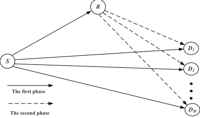
FIGURE 1:Downlink cooperative NOMA system.
As depicted in Fig. 1, we consider a common downlink cooperative network, where a source S communicates with
M usersD={D1, D2, . . . , DM}via a dedicated DF relay,
2According to the principle of power-domain NOMA, the users should be
sorted based on their channel conditions. That is to say, the strongest user is the one who has the best channel condition.
and the users are clustered to form homogeneous network topology [23]. All nodes in this system are equipped with a single antenna and all nodes know the exact channel state information (CSI). Unlike the assumption of absen-t direcabsen-t links in previous works, we consider absen-the direcabsen-t links between S and D are also present to model a more realistic situation. All the wireless links are assumed to experience independent Rayleigh fading and additive white Gaussian noise (AWGN). The channel vector betweenSand
D is denoted byhSD = [hSD1, hSD2,· · · , hSDM], where
hSDm ∼ CN(0,ΩX), m = 1,2,· · · , M. The channel
gain between S and R is denoted by hSR, where hSR ∼ CN(0,ΩY). Similarly betweenRandD, the channel vector
is denoted by hRD = [hRD1, hRD2,· · ·, hRDM], where hRDm ∼ CN(0,ΩZ), m = 1,2,· · · , M. For notational
simplicity, letλX = |hX| 2
, where X ∈ {SR, SDi, RDi}
withi∈ {1,2,· · ·M}.
As described in [13]-[17], the whole transmission of this half-duplex relay system is also completed in two consecu-tive phases.
During the first phase, the source S broadcasts the su-perimposed signal xS to R and D simultaneously, where xS is given by xS = PMi=1
√
aiPSxi, PS denotes the
transmit power at S, xi denotes the signal of Di, and ai denotes the corresponding power coefficient.
There-fore, the received signals at R and Di can be
writ-ten as yR = hSRP M i=1
√
aiPSxi + nR and ySDm = hSDm
PM
i=1 √
aiPSxi+n1Dm, wherenR∼ CN(0, σ
2 R)and n1D
m ∼ CN(0, σ
2 D1
m), denote the AWGNs at R andDm,
respectively.
Based on the principle of NOMA, the DF relay decodes the signals ofDusing SIC, Thus, the corresponding signal-to-interference-and-noise ratio (SINR) at relay is given by:
γmSR=
( a mλSR
eamλSR+ 1
ρ
, m < M
ρaMλSR, m=M ,
(1)
whereρ =∆ PS σ2
R
represents the average signal-to-noise ratio
(SNR), and˜am=P M i=m+1ai.
Meanwhile, SIC will also be carried out at D. UserDn
should decode the signal of userDmfirst before decoding its
own signal (n > m >1), and the signal ofDnwill be treated
as noise atDm. As a result, the SINR forDmto decode its
own signal can be calculated as:
γSDm = amλSDm eamλSDm+
1 ρ
. (2)
The SINRs forDMto decode the signal ofDmand its own
signal can be calculated respectively as:
γMSD→m= amλSDM e
amλSDM +
1 ρ
, (3)
γSDM =ρaMλSDM. (4)
During the second phase, the relay rebuilds the
superpo-sition code and retransmits it to all users with power PR
[17]. Therefore, the received signal at Dm can be written
as yRDm = h m RD
PM
i=1 √
aiPRxi +n2Dm, where nD2m ∼
CN(0, σ2 D2
m)denotes the AWGN atDmin the second phase.
As in [13]-[17], we also assume thatPS =PR =P,σR2 = σ2
D1
m = σ
2 D2
m = σ
2. Similar to (2)-(4), the corresponding
SINRs of linkR→Dcan be expressed as:
γRDm = amλRDm e
amλRDm+
1 ρ
, (5)
γRDM→m= amλRDM e
amλRDM+
1 ρ
, (6)
γRDM =ρaMλRDM. (7)
Finally, by using the MRC criterion, all users combine the received signals of the two-phase transmission. Taking into account the impact of both direct and relay-aided links, in the following sections, we analyze and compare two different user ordering schemes, i.e., the users are sorted according the channels gains of relay-aided links asλRD1 ≤λRD2 ≤ · · · ≤λRDM, or according the channels gains of direct links
asλSD1 ≤λSD2 ≤ · · · ≤λSDM.
III. OUTAGE PERFORMANCE
To evaluate the two different user ordering schemes, in this section, outage probability is characterized as a benchmark criterion of system performance.
A. ALL USERS ARE SORTED ACCORDING TO THE CHANNELS GAINS OF RELAY-AIDED (R→D) LINKS.
From the mechanism described in the last section, the link
S → R has a great impact on the SINR at users. If relay could decode the signals correctly, the user can combine the signals from both links S → D and R → D. Otherwise, only the signal from linkS → Dis available. Therefore, the outage probability of them-th user3can be given by
Pm
out=P γ m SR< γ
m tar, γ
m SD< γ
m tar
| {z }
Ψ1
+P γSRm ≥γtarm, γSDm +γmRD< γtarm
| {z }
Ψ2
, (8)
whereγm
tardenotes the target SINR forDm. The target rate
forDmis given byRm=12log2(1 +γtarm ).
The first part in (8) can be obtained as
Ψ1=P
amλSR
e amλSR+ρ1
< γm tar
P
amλSDm
e
a1λSDm+1ρ < γm
tar
=FλSR(τm)FλSDm(τm) =
1−e−τmΩY1−e−ΩτmX,
(9) whereτm =
γmtar
ρ(am−γmtaran). It is assumed thatγ m tar <
am an;
otherwise the outage probability ofDmis always one.
3For mathematical tractability, in Section III, we mainly consider the
Then, the second part of (8) can be calculated as
Ψ2=P γSRm ≥γ m tar
P γm
SD+γ m RD< γ
m tar
=e−ΩτmY P γSDm +γmRD< γtarm
| {z }
Ψ3
. (10)
AndΨ3can be further rewritten as follows:
Ψ3= 1−P((2ρ2aman−γtarmρ2an2)λRDmλSDm
+(ρam−γmtarρan)(λRDm+λSDm)≥γ m tar).
(11)
Recall the condition γm tar <
am
an, we have 2ρ
2a man− γtarm ρ2an2>0andρam−γtarm ρan >0. After some algebraic
manipulations, (11) can be revised as
Ψ3= 1−P(λRDm ≥max{0,
γmtar−bλSDm cλSDm+b })
= (
1−P(λRDm >
γtarm −bλSDm
cλSDm+b ), 0< λSDm < γmtar
b ;
1−P(λRDm >0), λSDm≥ γm
tar b ,
(12) whereb= (ρam−γmtarρan)andc= 2ρ2aman−γtarm ρ2an2.
With the aid of [26], the CDF ofλRDm is given by
FλRDm(x) = M
X
i=m i
X
j=0
(−1)j i
j !
M i
!
e−(j+M
−i)x
ΩZ .
(13)
Then,Ψ3can be expressed as
Ψ3= 1−
Rγmtarb
0 fλSDm(x)dx R∞
γmtar−bx cx+b
fλRDm(y)dy
+R∞ γmtar
b
fλSDm(x)dxR
∞
0 fλRDm(y)dy
= ∆e(j+M
−i)b
ΩZ c
Z γmtarb
0
e−[ΩxX+
(j+M−i)γmtar+(j+M−i)b
2
c
ΩZ cx+ΩZ b ]
| {z }
Ψ4
dx,
(14)
where ∆ = Ω1
X M
P
i=m i
P
j=0
(−1)j i j M i
. Let r denote
ΩZcx+ΩZb, andddenote(j+M−i)γmtar+
(j+M−i)b2 c , after
applying the series expansion of the exponential functions in (14), we have:
Ψ4=
RΩZ cγ m tar
b +ΩZb
ΩZb e
−r−ΩZ b
ΩXΩZ ce−drdr
=eΩX cb ∞
P
t=2 (−1)t
t! d tR
ΩZ cγmtar
b +ΩZb
ΩZb e
− r
ΩXΩZ cr−tdr
+RΩZ cγ m tar
b +ΩZb
ΩZb e
− r
ΩXΩZ cdr
−dR
ΩZ cγtarm
b +ΩZb
ΩZb e
− r
ΩXΩZ cr−1dr
,
(15)
The second part ofΨ4can be directly given by
Ψ24= ΩXΩZc
e−ΩX cb −e−
cγmtar b +b
ΩX c
. (16)
With the help of [27, eq.(3.351.4)] , the first part ofΨ4can
be calculated as
Ψ1
4= (−1)t 1
ΩXΩZ c
(t−1)
Ei −b 1
ΩX c
(t−1)! + e−
b
ΩX c
(ΩZb)t−1
× t−2
P
k=0
(−1)k 1
ΩXΩZ c
k
(ΩZb)k
(t−1)(t−2)···(t−1−k) −
(−1)t
× 1
ΩXΩZ c
(t−1)
Ei− cγmtar
b +b
1
ΩX c
(t−1)! + e−
cγmtar b +b
1
ΩX c
ΩZ cγm
tar
b +ΩZb
t−1
× t−2
P
l=0
(−1)l 1
ΩXΩZ c
l ΩZ cγtarm
b +ΩZb
l
(t−1)(t−2)···(t−1−l)
,
(17) where Ei(x) = Rx
−∞
et
tdt, x < 0. With the aid of [27,
eq.(3.352.2)], the third part ofΨ4can be calculated as
Ψ34=d
Ei−
cγmtar
b +b
ΩXc
−Ei− b
ΩXc
. (18)
Finally, by combining (8)-(10) and (14)-(18), the closed-form expression of the outage probability for the weak user
Dmcan be written as
Poutm = 1−e
−τm
ΩY 1−e−
τm
ΩX
+∆e−τmΩY+
(j+M−i)b
ΩZ c +ΩX cb 1
ΩZc ∞
P
t=2 (−1)t
t! d tΨ1
4+ Ψ24−Ψ34
.
(19)
On the other hand, the n-th user Dn should decode the
signal of Dm first before decoding its own signal, thus the
outage probability ofDncan be given by
Pn out =
h
1−P γn
SR≥γtarn , γSRm ≥γtarm
i
×h1−P γSDn ≥γtarn , γSDn→m≥γmtari
+P γSRn ≥γntar, γmSR≥γ m tar
h 1
−P(γSDn +γRDn ≥γntar, γnSD→m+γ n→m
RD ≥γ
m tar)
i .
(20)
Define the first part of (20) asΨ5, and the second part as
Ψ6. Subsequently,Ψ5can be further calculated as
Ψ5=
1−PρanλSR≥γtarn ,
amλSR
eamλSR+ 1
ρ
≥γm
tar
×
1−PρanλSDn≥γ n tar,
amλSDn anλSDn+1ρ
≥γtarm
=h1−P λSR≥max{τn, τm} ∆
=θi
×h1−P λSDn ≥θ
i
=1−e−ΩθY
1−e−ΩθX
,
(21) whereγtarn represents the target SINR ofDnandτn =
γn tar ρan.
The target rate forDnis given byRn=12log2(1 +γtarn ).
Then,Ψ6can be attained as
Ψ6=P |hSR| 2
≥θ
1
−P(λRDn+λSDn ≥τ
n, γn→m
SD +γ
n→m
RD ≥γ
m tar)
| {z }
Ψ7
=e−ΩθY(1−Ψ 7).
(22)
By substituting (3) and (6) into (22) and following similar steps to (12),Ψ7can be written as
Ψ7=P
λRDn ≥max
0,γ
m
tar−bλSDn cλSDn+b
, τn−λSDn
.
(23)
Ψ7 can be further calculated based on the relationship
between the function γtarm −bλSDn
cλSDn+b and function τ n−λ
SDn.
For the case ofτn ≥ γtarm
b , the outage probability of then-th
userDnis given by:
Poutn = 1−e−ΩθY 1−e− θ
ΩX
+Ω1
X M
P
i=n i
P
j=0
(−1)j i
j !
M i
!
e−ΩθY−
(j+M−i)τ n
ΩZ
× ΩXΩZ
[ΩZ−ΩX(j+M−i)]
1−e−
[ΩZ−ΩX(j+M−i)]τ n
ΩXΩZ
.
(24)
P roof: See Appendix A.
On the other hand, for the case ofτn <γtarm b and(τ
n)2c−
4(γm
tar−bτn) < 0,Poutn is given by (25). For the case of τn < γtarm
b and(τ
n)2c−4(γm
tar−bτn) ≥ 0, the outage
probability ofDncan be derived as (26), which are shown at
the top of the next page.
B. ALL USERS ARE SORTED ACCORDING TO THE CHANNELS GAINS OF DIRECT (S→D) LINKS.
In this user ordering scheme,{λSDi}are ordered instead
of{λRDi},i∈ {1,2,· · ·M}. Therefore, the CDF of{λSDi}
is given by
FλSDm(x) = M
X
i=m i
X
j=0
(−1)j i j M i e−
(j+M−i)x
ΩX . (27)
Then, the corresponding outage probability can be calcu-lated following the similar steps as in subsection III.A. In this situation, the closed-form expression ofDmcan be given by:
Pm
out = (1−e
−τm
ΩY )
M
P
i=m i
P
j=0
(−1)j i j M i e−
(j+M−i)τm
ΩX
+ M!
ΩXΩZc(m−1)!(M−m)! m−1
P
l=0
(−1)l
m−1
l
×eΩZ cb +
b
ΩX c−τmΩY
∞
P
t=1 (−1)t
t! d tΨ1
12+ Ψ212−Ψ312
,
(28)
where
Ψ1
12= (−1)t
(M−m+l+1
ΩXΩZ c )
(t−1)
Ei(−M−m+l+1
ΩX c b)
(t−1)!
+e
−M−m+l+1
ΩX c b
(ΩZb)t−1 t−2
P
k=0
(−1)k(M−Ωm+l+1
X c )
k
(b)k (t−1)(t−2)···(t−1−k)
−h(−1)t(
M−m+l+1
ΩXΩZ c )
(t−1)
Ei[−M−m+l+1
ΩX c (c
γmtar b +b)]
(t−1)!
+e
−M−Ωm+l+1
X c (c γmtar
b +b)
(ΩZ cγ
m tar b +ΩZb)
t−1 t−2
P
k=0
(−1)k(M−Ωm+l+1
X c )
k
(cγmtar b +b)
k
(t−1)(t−2)···(t−1−k)
i ,
Ψ212= ΩXΩZc
M−m+l+1e
−(M−m+l+1)ΩZ b
ΩXΩZ c
1−e−
(M−m+l+1)ΩZ cγmtar
bΩXΩZ c
,
and Ψ
3
12= (γtarm + b2
c){Ei[−
(M−m+l+1) ΩXc (
cγm tar b +b)] −Ei[−(M−Ωm+l+1)b
Xc ]}.
As for the strong userDn, ifτn ≥ γm
tar
b , the closed-form
expression of strong user can be given by:
Poutn =1−e−ΩθY M
P
i=n i
P
j=0
(−1)j i j M i e−
(j+M−i)θ
ΩX
+ M!ΩZ
(n−1)!(M−n)![ΩZ(M−n+k+1)−ΩX]e
−τ n
ΩZ−ΩθY
× n−1
P
k=0
(−1)k
n−1
k
h 1−e−
[ΩZ(M−n+k+1)−ΩX]τ n
ΩXΩZ
i .
(29) Finally, For the case of τn < γtarm
b , P n
out can be also
calculated following the similar steps to Appendix A, B, and (24)-(26).
IV. DIVERSITY GAIN
Since the closed-form expression of the outage probability in Section III is complex, it is also essential to study the diversity gain to provide more insights. To proceed, we defineΛRm,outas the event thatRcannot decode the signals
of {D1, D2, ..., Dm} successfully. Then the probability of
ΛRm,outis given by:
P(ΛRm,out) = 1−P(λSR> τ
∗
m) = 1−e
−τm∗
ΩY , (30)
whereτm∗ = max{τ1, τ2,· · ·, τm}withm < M, andτm∗ =
max{τ1, τ2,,· · ·, γtarM
ρaM}withm=M.
Next, we defineΦmas the outage event ofDm,Φm,jas the
event thatDmfails to decode the signal ofDj(1 ≤j ≤m)
after MRC, andΦc
m,jas the complementary set ofΦm,j. The
outage probability ofΦmcan be formulated as
P(Φm) = 1−P(Φcm,1∩Φ c
m,1∩ · · · ∩Φ c
m,m), (31)
in which, the probability ofΦm,jcan be written as
P(Φm,j) =P(ΛRm,out)P(γ m→j SD < γ
j tar)
+P(ΛcR
m,out)P(γ m→j
SD +γ
m→j RD < γ
j tar).
(32) It can be observed that the first part of (32) equals to the outage probability that only the direct links are available and
Dmfails to decodeDj. The second part equals to the outage
Pn
out= 1−e
− θ
ΩY 1−e−
θ
ΩX+ 1
ΩZc∆
0e− θ
ΩY+
(j+M−i)b
ΩZ c +
b
ΩX c
(
∞
P
t=2 (−1)t
t! d t(−1)t
1
ΩXΩZ c
(t−1)
Ei −b 1
ΩX c
(t−1)!
+e − b
ΩX c
(ΩZb)t−1 t−2
P
k=0
(−1)k 1
ΩXΩZ c
k
(ΩZb)k
(t−1)(t−2)···(t−1−k) −[(−1) t
1
ΩXΩZ c
(t−1)
Ei− cγmtar
b +b
1
ΩX c
(t−1)!
+ e − cγmtar
b +b 1
ΩX c
ΩZ cγm
tar
b +ΩZb
t−1 t−2
P
l=0
(−1)l 1
ΩXΩZ c
l Ω Z cγmtar
b +ΩZb
l
(t−1)(t−2)···(t−1−l) ] + ΩXΩZc
e−ΩX cb −e− cγmtar
b +b
ΩX c
−dhEi(−
cγmtar
b +b
ΩXc )−Ei(− b ΩXc)
i )
.
(25)
Pn
out= 1−e
− θ
ΩY 1−e−
θ
ΩX+∆0e−
θ
ΩY+
(j+M−i)b
ΩZ c +
b
ΩX c 1
ΩZc
µx1+ΩXΩZc
e−ΩX cb −e−
cx1 +b
ΩX c
−dhEi−cx1+b ΩXc
−Ei− b
ΩXc i
+ ∆0e−ΩθX−
(j+M−i)τ n
ΩZ ΩXΩZ
[ΩZ−ΩX(j+M−i)] n
e−
[ΩZ−ΩX(j+M−i)]x1
ΩXΩZ −e−
[ΩZ−ΩX(j+M−i)]x2
ΩXΩZ
o
+∆0e−ΩθX+
(j+M−i)b
ΩZ c +
b
ΩX c 1
ΩZc n
µx2+ΩXΩZc
e−
cx2 +b
ΩX c−e−
cγmtar b +b
ΩX c
−dhEi−
cγmtar
b +b
ΩXc
−Ei−cx2+b ΩXc
io ,
(26)
where ∆0= 1 ΩX
M
P
i=n i
P
j=0
(−1)j i j M i
,x1=
τnc−√(τnc)2−4c(γm tar−bτn)
2c andx2=
τnc+√(τnc)2−4c(γm tar−bτn)
2c ,
µx1 = ∞
P
t=2 (−1)t
t! d t
(−1)t
1
ΩXΩZ c
(t−1)
Ei −b 1
ΩX c
(t−1)! + e−
b
ΩX c
(ΩZb)t−1 t−2
P
k=0
(−1)k 1
ΩXΩZ c
k
(ΩZb)k
(t−1)(t−2)···(t−1−k)
−(−1)t 1
ΩXΩZ c
(t−1)
Ei−(cx1+b)ΩX c1
(t−1)! −
e−(cx1 +b) 1
ΩX c
(ΩZcx1+ΩZb)t−1 t−2
P
l=0
(−1)l 1
ΩXΩZ c
l
(ΩZcx1+ΩZb)l
(t−1)(t−2)···(t−1−l)
,
µx2 = ∞
P
t=2 (−1)t
t! d t
(−1)t ΩX1ΩZ c
(t−1)
Ei −cx2 +b
ΩX c
(t−1)! + e−
cx2 +b
ΩX c
(ΩZcx2+ΩZb)t−1 t−2
P
k=0
(−1)k 1
ΩXΩZ c
k
(ΩZcx2+ΩZb)k
(t−1)(t−2)···(t−1−k)
−(−1)t ΩX1ΩZ c
(t−1)
Ei− cγmtar
b +b
1
ΩX c
(t−1)! −
e− cγmtar
b +b 1
ΩX c
ΩZ cγtarm
b +ΩZb
t−1 t−2
P
l=0
(−1)l 1
ΩXΩZ c
l ΩZ cγmtar
b +ΩZb
l
(t−1)(t−2)···(t−1−l)
.
P roof: See Appendix B.
Φmcan be bounded as
P(Φm)≤P(λSR< τm∗)P(λSDm< τ
∗
m)
| {z }
J1
+P(λSR≥τm∗)P(λRDm< τ
∗
m)P(λSDm< τ
∗
m)
| {z }
J2
.
(33)
A. ALL USERS ARE SORTED ACCORDING TO THE CHANNELS GAINS OF RELAY-AIDED (R→D) LINKS.
In this user ordering scheme,λSDm is an unordered
vari-able, thenJ1can be given by
J1=P(λSR< τm∗)P(λSDm < τ
∗
m)
= (1−e− τm∗
ΩY )(1−e−
τm∗
ΩX)∝ 1
ρ2,
(34)
where ∝ denotes the approximation at high SNR. Also,
P(λSR ≥τm∗)P(λSDm < τ
∗
m)inJ2is given bye −τm∗
ΩY(1−
e− τ∗m
ΩX). Then, the PDF ofλRD
m is given by f
λRDm(x) =
M! ΩZ(m−1)!(M−m)!
× m−1
P
i=0
(−1)i
m−1
i
e−
(M−m+i+1)x
ΩZ .
(35)
The high-SNR approximations of P(λRDm < τ
∗
m)can
be obtained following the steps to (36)-(39), which can be approximated as ρ1m. By substituting J1, andJ2 into (33),
we can conclude that all the users can experience a same diversity order as two.
B. ALL USERS ARE SORTED ACCORDING TO THE CHANNELS GAINS OF DIRECT (S→D) LINKS.
In this scheme, the PDF ofλSDmis given by
f
λSDm(x) =
M! (m−1)!(M−m)!
1 ΩX
× m−1
P
i=0
(−1)i
m−1
i
e−
(M−m+i+1)x
ΩX .
(36)
Then,P(λSDm < τ
∗
m)can be obtained as:
P(λSDm<τ
∗
m) =
Rτm∗
0 fλSDm(x)dx
= (m−1)!(MM! −m)!M−m1+i+1
× m−1
P
i=0
(−1)i
m−1
i
1−e−
(M−m+i+1)τm∗
ΩX
∆
=
∞
P
l=1
(−1)l+1M!τ∗
ml
(m−1)!(M−m)!l!ΩXl l−1
P
j=0
l−1
j
×(M−m+ 1)l−1−jmP−1
i=0
m−1
i
(−1)iij,
(37) where=∆ denotes the series expansion of exponential func-tions.
Recall Equations (24)-(25) in [13], and sums of the binomial coefficients in [27, (Eq.(0.154.3)] and [27, (E-q.(0.154.4)]. It is interesting to observe that, in the high SNR region, all the components containingij in (37), j <
(m−1), can be removed. Also, the components containing
ij,j > (m−1), can also be ignored. Therefore,J1can be
approximated as
J1'
M!τ∗mm+1
(M −m)!m!ΩXmΩY
∝ 1
ρm+1. (38)
Meanwhile, since λRDm is an unordered variable, P(λSR≥τm∗)P(λRDm < τ
∗
m)inJ2can be directly obtained
as:
P(λSR≥τm∗)P(λRDm< τ
∗
m)=e
−τm∗
ΩY(1−e−
τm∗
ΩZ)∝ 1
ρ.
(39)
Therefore, at high SNR regions ,J2can be also
approx-imated as ρm1+1. By combining J1 andJ2 in (33), we can
conclude that, in this user ordering scheme, the m-th user can achieve a diversity order ofm+ 1.
V. ERGODIC RATE
In Sections III and IV, we mainly investigate the outage performance and diversity gain under the assumption that each user has a preset quality of service (QoS) requirement, and it is shown that the second user ordering scheme can achieve better diversity order. However, the diversity order by itself does not tell the entire story. Due to the significant benefits of NOMA on better user fairness and larger capacity, it is also interesting to discuss the users’ ergodic rate as an alternative criterion.
As described in [24], in this situation, the user’s rate is determined opportunistically by the user’s channel condition instead of a preset value.
A. ALL USERS ARE SORTED ACCORDING TO THE CHANNELS GAINS OF RELAY-AIDED (R→D) LINKS.
We first focus on the ergodic rate of them-th (1 ≤m ≤ M − 1) user. According to the mechanism described in
Section II,γmis given by:
γm= max
min{γSDm , γSDm→m+1,· · ·, γSDm→M}, min{γmSR, γm
RD+γmSD, γ m→m+1
RD +γ
m→m+1
SD ,· · ·, γ
m→M
RD +γSDm→M} .
(40) In light of (2), (3), (5), and (6), in the high-SNR region (ρ→ ∞),γmcan be approximated asam/afm, which means whenρ→ ∞, the ergodic sum rate of this system is mainly determined by theM-th user rather than the restM−1users. As for the M-th user, the corresponding SINR can be expressed as:
γM = max{γMSD, min(γ M SR, γ
M RD+γ
M SD)}
=aMρmax
λSDM, min{λSR, λRDM+λSDM} .
(41) To addressγM, we letω=max[λSDM, min(λSR, λRDM+ λSDM)], and the CDF ofωcan be expressed as:
Fω(x)=1−e
− x
ΩY−e−ΩxX+e−ΩxY−ΩxX+
M
P
k=0
M
k
(−1)k+1
× k
ΩXk−ΩZ hΩ
Z k e
−x
ΩY−ΩkxZ−e−ΩxY−Ω
X(e
− x
ΩX−ΩxY −e−ΩxY)
−ΩZ k (e
−kx
ΩZ−ΩxY−ΩxX−e−ΩxY−ΩxX)+Ω
X(e
−2x
ΩX−ΩxY−e−ΩxY−ΩxX)
i .
(42)
P roof: See Appendix C.
Then, the ergodic rate ofM-th user is given by
RM =Eh1
2log(1 +γM) i
= aMρ 2 ln 2
Z ∞
0
1−Fω(x)
1 +aMρx dx.
(43) By substituting (42) into (43) and with the aid of [27, (Eq.(3.352.4)], we can calculate the ergodic rate ofM-th user as (44).
B. ALL USERS ARE SORTED ACCORDING TO THE CHANNELS GAINS OF DIRECT (S→D) LINKS.
On the other hand, if only the direct links are ordered, the
m-th user’s SINRγmis given by:
γm= max
γm
SD, min(γ m SR, γ
m RD+γ
m SD, γRDm→m+1+γSDm→m+1,· · ·, γm→M
RD +γSDm→M)
.
(45) Similarly, again applying the high SNR approximation, (45) can be approximated asam/afm.
Also, theM-th user’s SINR is still given by (41). Note that in this situation, the ordered variables are{λSDm}instead of
{λRDm}, so the CDF ofωis different. Following the similar
steps as subsection V.A,RM can be given by (46), as shown
at the top of pape 8.
VI. NUMERICAL RESULTS
In this section, computer simulations are provided to e-valuate the two different user ordering schemes (scheme A: sort users according to links R → D, scheme B: sort users according to links S → D), and the corresponding analytical results. We consider that the base station, the relay node, and users are located on a straight line.ΩY = d1−α,
RM = 1 2 ln 2
h Γ1−
M
P
k=0
M
k
(−1)k+1 1
ΩXk−ΩZ(Γ2−Γ3) i
, (44)
where Γ1=−e 1
aM ρΩY Ei
− 1
aMρΩY
−eaM ρ1ΩXEi
− 1
aMρΩX
+e
ΩX+ΩY
aM ρΩXΩYEi
− ΩX+ ΩY
aMρΩXΩY
,
Γ2=ΩZ
h
−e
ΩZ+kΩY
aM ρΩYΩZEi−ΩZ+kΩY aMρΩYΩZ
+eaM ρ1ΩYEi− 1 aMρΩY
i
−kΩX
h
−e
ΩY+ΩX
aM ρΩXΩYEi− ΩY+ΩX aMρΩXΩY
+eaM ρ1ΩYEi− 1 aMρΩY
i ,
Γ3= ΩZ
h
−e
kΩYΩX+ΩZΩX+ΩZΩY
aM ρΩZΩYΩX Ei
−kΩYΩX+ΩZΩX+ΩZΩY aMρΩZΩYΩX
+e
ΩX+ΩY
aM ρΩYΩXEi
− ΩX+ΩY
aMρΩYΩX i
−kΩX
h
−e
2ΩY+ΩX
aM ρΩYΩXEi
− 2ΩY+ΩX
aMρΩYΩX
+e
ΩX+ΩY
aM ρΩYΩXEi
− ΩX+ΩY
aMρΩYΩX i
.
RM = 1
2 ln 2 h
Γ4− M
X
j=0
M
j M
X
k=0
M
k
(−1)k+1+j(Γ5+ Γ6)
i
, (46)
where Γ4= M
X
j1=1
M
j1
(−1)j1e
j1
aM ρΩXEi
− j1
aMρΩX
− M
X
j2=0
M j2
(−1)j2e
j2 ΩY+ΩX aM ρΩXΩYEi
−j2ΩY + ΩX aMρΩXΩY
,
Γ5=
ΩX
ΩZk−ΩX
h
−e
jΩY+ΩX+kΩY aM ρΩXΩY Ei
−jΩY + ΩX+kΩY
aMρΩXΩY
+e
jΩY+ΩX aM ρΩXΩY Ei
− jΩY + ΩX
aMρΩXΩY
i ,
Γ6=
kΩZ
ΩZk−ΩX
h
−e
jΩYΩZ+ΩXΩZ+ΩXΩY
aM ρΩXΩYΩZ Ei
−jΩYΩZ+ ΩXΩZ+ ΩXΩY
aMρΩXΩYΩZ
+e
jΩY+ΩX
aM ρΩXΩY Ei
− jΩY + ΩX
aMρΩXΩY
i .
1−d1 denote the distance of S → R andR → D after
normalization4.
A. OUTAGE PERFORMANCE & DIVERSITY GAIN
0 5 10 15 20 25 30
SNR(dB) 10-4
10-3
10-2
10-1
100
Outage Probability
Solid Line: The Analytical Results
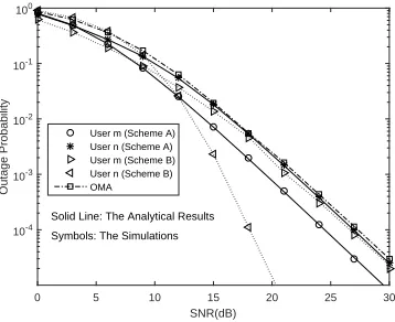
[image:8.576.38.542.62.371.2]Symbols: The Simulations User m (Scheme A) User n (Scheme A) User m (Scheme B) User n (Scheme B) OMA
FIGURE 2: Two users scenario withm = 1,n = M = 4,
am= 0.8,an= 0.2,d1= 0.5,γtarm = 2.5dB, andγtarn = 4dB.
By using the Monte Carlo method, in Figs. 2 and 3, we first provide the outage performance comparisons among different user ordering schemes by varying the average SNR. In Fig. 2, we also set the OMA system as a comparison candidate, where the target SINR γOM A of user in OMA
system satisfies 12log2(1 +γOM A) = Rm+Rn. As can
4This path loss model has been well explained in [25], and it has also been
widely used in numerous works [13]-[17]
0 5 10 15 20 25 30
SNR(dB) 10-5
10-4
10-3 10-2
10-1
100
Outage Probability
Solid Line: Scheme A
[image:8.576.324.506.381.526.2]Dotted Line: Scheme B User 1 User 2 User 3
FIGURE 3:Three users scenario withM = 3a1 = 1/2,a2=
1/3,a3= 1/6,γtar1 = 0.9dB,γ2tar= 1.5dB, andγtar3 = 2dB.
be observed, both two NOMA schemes outperform conven-tional OMA scheme. The reason is that NOMA can serve the two users simultaneously in two time phases, whereas four time phases are needed to complete the transmission of two users for conventional OMA scheme. Then, we can see that the simulation results match very well with the derived analytical results in (19), (24)-(26), and (28)-(29), which exactly verifies the accuracy of our derivations. In Fig. 3, we further present the outage performance of three users scenario as an extension. It can be observed that, for scheme A, the outage probabilities of all users show similar trends, and all users can experience the same diversity gain of two. By contrast, for scheme B, the outage probabilities of
[image:8.576.64.243.441.587.2]different users show different trends, and them-th user can achieve a diversity gain ofm+ 1, which is also consistent with our analysis provided in Section IV.
0.6 0.65 0.7 0.75 0.8 0.85 0.9 a
m
10-3
10-2
10-1
100
Outage Probability
Solid Line: The Analytical Results Symbols: The Simulations User m (Scheme A)
[image:9.576.333.506.67.214.2]User n (Scheme A) User m (Scheme B) User n (Scheme B) OMA
FIGURE 4:Outage probability vs.amwithd1 = 0.5,m= 1,
n=M = 4,ρ= 10dB,γm
tar= 1dB, andγtarn = 3dB.
0.1 0.2 0.3 0.4 0.5 0.6 0.7 0.8 0.9 d
1
10-4
10-3
10-2 10-1
100
Outage Probability
Solid Line: The Analytical Results Symbols: The Simulations User m (Scheme A)
User n (Scheme A) User m (Scheme B) User n (Scheme B) OMA
FIGURE 5:Outage probability vs.d1withm= 1,n=M = 4,
ρ = 15dB,d1 = 0.5,am = 0.8,an = 0.2,γtarm = 1dB, and
γn
tar= 3dB.
In Figs. 4 and 5, we illustrate outage performance by varyingamandd1, respectively. Firstly, it can be seen that the
exact analytical results match very well with the simulations in both Figs. 4 and 5. Then, from Fig. 4, we can observe that
am has a considerable impact on the outage probability of
users. For fixed preset target SINR, the outage probability of user mdecreases and that of usern increases witham.
Moreover, the position of relay also has a significant impact on outage performance (see Fig. 5), especially for scheme A. Since the relay is more likely to decode and retransmit the signals successfully when it is near to the source (d1≤0.4),
sorting user according to the linksR→ Dis more efficient in this case. However, when relay is far away from source, the decoding is more difficult for relay, and the outage performance gap between scheme A and OMA narrows with
d1.
0 5 10 15 20 25 30
SNR(dB) 0
1 2 3 4 5 6 7
Rate
Solid Line: Scheme A
[image:9.576.64.242.123.265.2]Dotted Line: Scheme B User 1 User 2 User 3 Sum Rate The Analytical Results
FIGURE 6:Ergodic rate vs.ρwithd1 = 0.5,a1 = 1/2,a2 =
1/3,a3= 1/6.
B. ERGODIC RATE
To obtain more insightful results, we next analyze the ergodic rate of users under different user ordering schemes. In Fig. 6, the ergodic rate is shown as a function of average SNR. Firstly, we can see the exact analytical results in (44) and (46) match very well with the simulations, which con-firms the correctness of our derivations. Then, it can be seen that, for user m(m < M), the ergodic rate nearly remains unchanged at high SNR. By contrast, the ergodic rate of the
M-th user is highly related to average SNR. That is to say, in the high-SNR region, the ergodic sum rate mainly depends on theM-th user, which is also consistent with the description in Section V. Another observation from Fig. 6 is the difference of two user ordering schemes. When the relay’s position is in the middle between source and users, userDM’s ergodic
rate of scheme A is larger than that of scheme B, thus also resulting in a larger ergodic sum rate.
0.1 0.2 0.3 0.4 0.5 0.6 0.7 0.8 0.9 d1
0 0.5 1 1.5 2 2.5 3 3.5
Rate
Solid Line: Scheme A Dotted Line: Scheme B
User 1 User 2 User 3 Sum Rate The Analytical Results
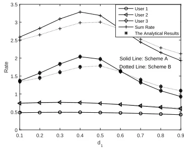
FIGURE 7: Ergodic rate vs.d1 with ρ = 10dB, a1 = 1/2,
a2= 1/3,a3= 1/6.
Fig. 7 depicts the performance of different user ordering schemes by varyingd1. As can be observed, the position of
[image:9.576.63.245.332.472.2] [image:9.576.323.505.487.634.2]d1 > 0.6, scheme B is the better one. This is because the
relay’s decoding task is more difficult when it is far from the source. Comparing scheme A with scheme B, we can find that, scheme A can achieve larger ergodic rate in some cases, while scheme B is less sensitive to relay’s location. This observation also justifies the analysis in Fig. 5.
VII. CONCLUSION
In this paper, two major user ordering schemes in cooper-ative NOMA have been analyzed and compared from two aspects: the outage performance and ergodic rate. As for outage performance, we have derived the closed-form expres-sions of users, and then obtained the corresponding diversity gain. As for ergodic rate, exact closed-form expression of the strongest user, and upper bounds of the rest users in the high-SNR region have been derived. Monte Carlo simulations have demonstrated that, on one hand, sorting users based on relay-aid path can provide larger ergodic sum rate in some cases, and on the other hand, sorting users based on direct path is less sensitive to the relay’s location, and can provide larger diversity gain.
.
APPENDIX A PROOF OF (24)
To address (23), we first assume τn ≥ γtarm b . Note
that b > 0 and c > 0, it can be observed that (τn)2c−4(γtarm −bτn) > 0. Consequently, if λSDn ∈ τnc−√(τnc)2−4c(γm
tar−bτn)
2c ,
τnc+√(τnc)2−4c(γm tar−bτn)
2c
, we
have γmtar−bλSDn cλSDn+b < τ
n −λ
SDn. Furthermore, it can be
also observed that τ
nc−√(τnc)2−4c(γm tar−bτn)
2c < 0 as well
as τ
nc+√(τnc)2−4c(γm tar−bτn)
2c > τ
n. Accordingly,Ψ 7can be
calculated as (47):
Ψ7=
Rτn
0 fλSDn(x)dx R∞
τn−xfλRDn(y)dy
+Rτ∞nfλSDn(x)dx
R∞
0 fλRDn(y)dy
= 1 + Ω1
X M
P
i=n i
P
j=0
(−1)j+1 i
j !
M i
!
e−
(j+M−i)τ n
ΩZ
× ΩXΩZ
[ΩZ−ΩX(j+M−i)]
1−e−
[ΩZ−ΩX(j+M−i)]τ n
ΩXΩZ
.
(47) Therefore, by combining (20)-(22), and (47), the outage probability of then-th userDncan be attained as (24) for the
case ofτn≥ γtarm b .
APPENDIX B
PROOF OF (25) AND (26) Ifτn< γtarm
b ,(τ
n)2c−4(γm
tar−bτn)≥0may not always
hold. Then, for the case ofτn< γmtar b and(τ
n)2c−4(γm tar− bτn)<0, we have γmtar−bλSDn
cλSDn+b > τ n−λ
SDn, andΨ7can
be calculated as:
Ψ7=R
γmtar b
0 fλSDn(x)dx R∞
γmtar−bx cx+b
fλRDn(y)dy
+R∞ γmtar
b
fλSDn(x)dx R∞
0 fλRDn(y)dy.
(48)
Consequently, by following the similar steps to (14)-(18), the outage probability of Dn in this case can be derived as
(25).
For the case ofτn <γtarm b and(τ
n)2c−4(γm
tar−bτn)≥0,
it can be verified that both the two intersection points of the two functions γmtar−bλSDn
cλSDn+b andτ n −λ
SDn exist.
Fur-ther define x1 =
τnc−√(τnc)2−4c(γm tar−bτn)
2c and x2 = τnc+√(τnc)2−4c(γm
tar−bτn)
2c . Note that0 < x1 ≤x2 < γm
tar b ,
andΨ7can be given by
Ψ7=
Z x1
0
fλSDn(x)dx
Z ∞
γmtar−bx cx+b
fλRDn(y)dy
| {z }
Ψ8
+ Z x2
x1
fλSDn(x)dx
Z ∞
τn−x
fλRDn(y)dy
| {z }
Ψ9
+ Z γmtarb
x2
fλSDn(x)dx
Z ∞
γmtar−bx cx+b
fλRDn(y)dy
| {z }
Ψ10
+ Z ∞
γmtar b
fλSDn(x)dx
Z ∞
0
fλRDn(y)dy
| {z }
Ψ11
.
(49)
Therefore, following the similar steps to (14)-(18),Ψ8can
be calculated as
Ψ8= 1−e−
x1
ΩX+e
(j+M−i)b
ΩZ c +
b
ΩX c 1
ΩXΩZc M
P
i=n i
P
j=0
(−1)j+1
× i
j !
M i
! n
µx1+ ΩXΩZc
e−ΩX cb −e− cx1 +b
ΩX c
−dhEi(−cx1+b ΩXc )−Ei
− b
ΩXc io
.
(50)
Then, following the similar steps in (47), Ψ9 can be
calculated as
Ψ9=
Rx2 x1
1 ΩXe
− x
ΩXdxR∞
τn−xfλRDn(y)dy
=e− x1
ΩX −e−
x2
ΩX + 1
ΩX M
P
i=n i
P
j=0
(−1)j+1 i
j !
M i
!
×e−
(j+M−i)τ n
ΩZ ΩXΩZ
[ΩZ−ΩX(j+M−i)]
×e−
[ΩZ−ΩX(j+M−i)]x1
ΩXΩZ −e−
[ΩZ−ΩX(j+M−i)]x2
ΩXΩZ
.
(51)
Similar toΨ8,Ψ10can be calculated as
Ψ10=e
−x2
ΩX −e−
γmtar b
ΩX +e
(j+M−i)b
ΩZ c +
b
ΩX c 1
ΩXΩZc
× M
P
i=n i
P
j=0
(−1)j+1 i
j !
M i
! n
µx2+ ΩXΩZc
×e− cx2 +b
ΩX c −e−
cγmtar b +b
ΩX c
−dhEi−
cγmtar
b +b
ΩXc
−Ei−cx2+b ΩXc
io .
(52)
Ψ11can be obtained directly as
Ψ11=
Z ∞
γmtar b
1 ΩX
e−ΩxXdx Z ∞
0
fλRDn(y)dy=e− γmtar bΩX.
(53) Finally, by substituting (49)-(53) into (20), we can derive the outage probability of then-th user, thus completing the proof of (26).
APPENDIX C PROOF OF (42)
In this scheme, the PDF ofλRDM is given by
fλRDM(x) = k
ΩZ M
X
k=0
M
k
(−1)k+1e−ΩxkZ. (54)
Subsequently, the PDF ofλRDM +λSDM can be expressed
by
fλRDM+λSDM(z) =
R+∞
−∞ fλRDM(x)fλSDM(z−x)dx
=
M
P
k=0
M
k
(−1)k+1Ωk
Z
1 ΩXe
− z
ΩX Rz
0 e
−(ΩX k−ΩZ)x
ΩXΩZ dx
=
M
P
k=0
M
k
(−1)k+1Ω k
Xk−ΩZ e
− z
ΩX −e−
kz
ΩZ.
(55) Accordingly, the CDF ofλRDM +λSDM can be calculated
based on (55). Finally, the CDF ofωis given by
Fω(x) =FλSDM(x)Fmin(λSR,λRDM+λSDM)(x)
=FλSDM(x){1−[1−FλSR(x)][1−FλRDM+λSDM(x)]}
= 1−e−ΩxX n
1−e−ΩxY n
1− M
P
k=0
M
k
(−1)k+1
× k
ΩXk−ΩZ ΩZ
k (e
−kx
ΩZ −1)−Ω
X(e− x
ΩX −1)
oo .
(56)
REFERENCES
[1] J. G. Andrews, S. Buzzi, W. Choi, S. V. Hanly, A. Lozano, A. C. K. Soong, and J. C. Zhang, “What will 5G be?” in IEEE J. Sel. Areas Commun., vol. 32, no. 6, pp. 1065-1082, June 2014.
[2] Q. Li, H. Niu, A. Papathanassiou, and G. Wu, “5G network capacity:Key elements and technologies,” in IEEE Veh. Technol. Mag., vol. 9, no. 1, pp. 71-78, Mar. 2014.
[3] L. Yang, J. Chen, Q. Ni, J. Shi, and X. Xue, “NOMA-enabled Coopera-tive Unicast-Multicast: Design and Outage Analysis,” in IEEE Trans. on Wireless Commun., vol. 16, no. 12, pp. 7870-7889, Dec. 2017. [4] Y. Sun, D. W. K. Ng, Z. Ding, and R. Schober, “Optimal Joint Power
and Subcarrier Allocation for Full-Duplex Multicarrier Non-Orthogonal Multiple Access Systems,” in IEEE Trans. on Commun., vol. 65, no. 3, pp. 1077-1091, Jan. 2017.
[5] Y. Sun, D. W. K. Ng, Z. Ding and R. Schober, “Optimal Joint Power and Subcarrier Allocation for MC-NOMA Systems,” in 2016 IEEE Global Communications Conference (GLOBECOM), Washington, DC, USA, Dec. 2016, pp. 1-6.
[6] V. W. S. Wong, et al., Key Technologies for 5G Wireless Systems. Cambridge, UK, 2017.
[7] A. Benjebbovu et al., “Concept and practical considerations of non-orthogonal multiple access (NOMA) for future radio access,” in Proc. IEEE ISPACS, 2013, pp. 770-774.
[8] Z. Ding, M. Peng, and H. V. Poor, “Cooperative non-orthogonal multiple access in 5G systems,” in IEEE Commun. Lett., vol. 19, no. 8, pp. 1462-1465, Aug. 2015.
[9] Z. Wei, L. Dai, D. W. K. Ng, and J. Yuan,“Performance Analysis of a Hybrid Downlink-Uplink Cooperative NOMA Scheme”, in 2017 Vehicu-lar Technology Conference (VTC Spring), Sydney, NSW, Australia, Jun. 2017, doi: 10.1109/VTCSpring.2017.8108407.
[10] L. Lv, J. Chen, and Q. Ni, “Cooperative Non-Orthogonal Multiple Access in Cognitive Radio,” in IEEE Commun. Letters, vol. 20, no. 10, pp. 2059 -2062, Aug. 2016.
[11] L. Lv, J. Chen, Q. Ni, and Z. Ding. “Design of Cooperative Non-Orthogonal Multicast Cognitive Multiple Access for 5G Systems: User Scheduling and Performance Analysis”, in IEEE Trans on Commun., vol. 65, no. 6, pp. 2641-2656, Jun. 2017.
[12] G. Liu, X. Chen, Z. Ding, Z. Ma, and F. R. Yu, “Hybrid Half-Duplex/Full-Duplex Cooperative Non-Orthogonal Multiple Access With Transmit Power Adaptation,” in IEEE Trans. on Wireless Commun., vol. 17, no.1, pp. 506-519, Nov. 2017.
[13] J. Men and J. Ge, “Performance analysis of non-orthogonal multiple access in downlink cooperative network,” in IET Commun., vol. 9, no. 18, pp. 2267-2273, Dec. 2015.
[14] J. Men, and J. Ge, C. Zhang, “Performance analysis of Non-Orthogonal Multiple Access for relaying networks over Nakagami-m fading channels,” in IEEE Trans. on Vehicular Technology, vol. 66, no. 2, pp. 1200-1208, Feb. 2017.
[15] J. Men, and J. Ge, “Non-orthogonal multiple access for multiple-antenna relaying networks,” in IEEE Commun. Lett., vol. 19, no. 10, pp. 1686-1689, Oct. 2015.
[16] Y. Zhang, J. Ge, and E. Serpedin, “Performance analysis of non-orthogonal multiple access for downlink networks with antenna selection over Nakagami-m fading channels,” in IEEE Trans. on Vehicular Technology, vol. 66, no. 11, pp. 10590-10594, Sep. 2017.
[17] D. Wan, M. Wen, F. Ji, Y. Liu, and Y. Huang, “Cooperative NOMA Systems With Partial Channel State Information Over Nakagami-m Fading Channels”, in IEEE Trans. on Commun., vol. 66, no. 3, pp. 947-958, Nov. 2017.
[18] Y. Sun, D. W. K. Ng, and R. Schober, “Resource Allocation for MC-NOMA Systems with Cognitive Relaying,” in 2017 IEEE Globe-com Workshops (GC Wkshps), Singapore, Singapore, Jan. 2018, doi: 10.1109/GLOCOMW.2017.8269087.
[19] Y. Xiao, L. Hao, Z. Ma, Z. Ding, Z. Zhang, and P. Fan, “Forwarding Strategy Selection in Dual-Hop NOMA Relaying Systems”, in IEEE Commun. Lett.,doi: 10.1109/LCOMM.2018.2803809, to be published in 2018.
[20] Z. Song, Q. Ni, and X. Sun,“Distributed Power Allocation for Nonorthogo-nal Multiple Access Heterogeneous Networks”, in IEEE Commun. Letters, vol. 22, no. 3, pp. 622-625, Jan. 2018.
[21] Y. Saito, Y. Kishiyama, A. Benjebbour, T. Nakamura, A. Li, and K.Higuchi, “Non-orthogonal multiple access (NOMA) for cellular future radio access," in Proc. IEEE Vehicular Technology Conference (VTC), Dresden, Germany, Jun. 2013.
[22] Z. Ding, X. Lei, G. Karagiannidis, R. Schober, J. Yuan, and V. Bhargava, “A Survey on Non-Orthogonal Multiple Access for 5G Networks: Re-search Challenges and Future Trends,” in IEEE J. Sel. Areas Commun., vol. 35, no. 10, pp. 2181-2195, Jul. 2017.
[23] Y. Xu, H. Sun, R. Q. Hu, and Y. Qian, “Cooperative non-orthogonal mul-tiple access in heterogeneous networks,” in Proc. IEEE Global Commun. Conf. (GlobeCom), San Diego, CA, USA, Dec. 2015, pp. 1-6.
[24] Z. Ding, Z. Yang, P. Z. Fan, and H. V. Poor, “On the performance of non-orthogonal multiple access in 5G systems with randomly deployed users,” in IEEE Signal Process. Lett., vol. 21, no. 12, pp. 1501-1505, Dec. 2014. [25] J. Li, L. J. Cimini, J. Ge, C. Zhang, and H. Feng, “Optimal and Suboptimal
Joint Relay and Antenna Selection for Two-Way Amplify-and-Forward Relaying,” in IEEE Trans. on Wireless Commun., vol. 15, no. 2, pp. 980-993, Feb. 2016.
[26] H. A. David and H. N. Nagaraja, ‘Order Statistics’, 3rd edn, New York, USA, 2003.
JIAN ZHANGreceived the B.Sc. and M.Sc. de-grees in School of Telecommunications Engineer-ing from Xidian University, Xi’an, China, in 2010, and 2014, respectively. He is currently working towards the Ph.D. degree in communication and information system at the same university. In particular, He is very interested in performance analysis of wireless communication systems. His current research interests are in the fields of coop-erative networks, non-orthogonal multiple access (NOMA), and energy harvesting.
JIANHUA GE received his Ph.D. degree in Schoolof Telecommunications Engineering from Xidian University, Xi’an, China, in 1990. He is currently a Professor and the Deputy Director of the State Key Laboratory of Integrated Services Networks, School of Telecommunications Engi-neering, Xidian University. He has worked on digital television (DTV) standardization as a DTV technical expert. His research interests include digital communications, digital video broadcast-ing, performance enhancement techniques for 4G/5G cellular communica-tion systems.
QIANG NI (M’04-SM’08) received the B.Sc., M.Sc., and Ph.D. degrees in engineering from the Huazhong University of Science and Technolo-gy, China, in 1993, 1996, and 1999, respectively. He is currently a Professor and the Head of the Communication Systems Group, School of Com-puting and Communications, Lancaster Universi-ty, Lancaster, U.K. His research interests include the area of future generation communications and networking, including green communications and networking, cognitive radio network systems, heterogeneous networks, 5G, SDN, cloud networks, energy harvesting, wireless information and power transfer, IoTs, cyber physical systems, machine learning, big data analytics, and vehicular networks. He has authored or co-authored over 200 papers in these areas. He was an IEEE 802.11 Wireless Standard Working Group Voting Member and a Contributor to the IEEE Wireless Standards.
MIAOWEN WEN (M’14-SM’18) received the B.S. degree from Beijing Jiaotong University, Bei-jing, China, in 2009, and the Ph.D. degree from Peking University, Beijing, China, in 2014. From 2012 to 2013, he was a Visiting Student Research Collaborator with Princeton University, Princeton, NJ, USA. He is currently an Associate Professor with the South China University of Technology, Guangzhou, China. He has published a Springer book entitled Index Modulation for 5G Wireless Communications and over 90 research papers, which include over 50 journal papers and over 30 conference papers. His research interests include index modulation, non-orthogonal multiple access, physical layer security, and molecular communications.
Dr. Wen was the recipient of the Excellent Doctoral Dissertation Award from Peking University and the Best Paper Awards from the IEEE Inter-national Conference on Intelligent Transportation Systems Telecommuni-cations (ITST) in 2012, the IEEE International Conference on Intelligent Transportation Systems (ITSC) in 2014, and the IEEE International Confer-ence on Computing, Networking and Communications (ICNC) in 2016. He was recognized as an Exemplary Reviewer for the IEEE Communications Letters in 2017. He is currently serving as a symposium co-chair for the IEEE ICNC2019, a workshop co-chair for the IEEE/CIC International Conference on Communications in China (ICCC’2018), and a Guest Editor for IEEE Journal on Selected Areas in Communications (Special Issue on Spatial Modulation for Emerging Wireless Systems) and for IEEE Journal of Selected Topics in Signal Processing (Special Issue on Index Modulation for Future Wireless Networks: A Signal Processing Perspective). He has served on the Editorial Boards of several international journals, including the IEEE Access, the EURASIP Journal on Wireless Communications and Networking, the ETRI Journal, and the Physical Communication (Elsevier).
YANGYANG ZHANGreceived the B.S. degree from the School of Telecommunications Engineer-ing, Xi’an Polytechnic University, Xi’an, China, in 2014. She is currently pursuing the Ph.D. de-gree in communication and information system with Xidian University. She is very interested in performance analysis of wireless communication systems. Her current research interests are in the fields of cooperative networks, non-orthogonal multiple access, and energy harvesting.