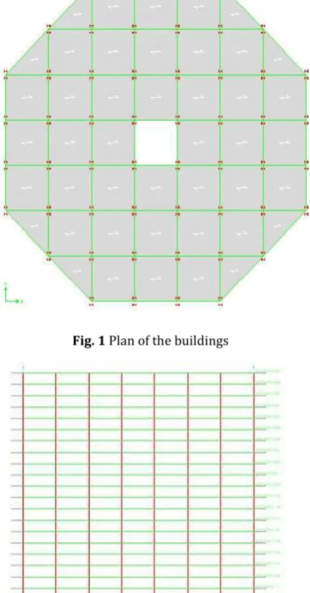
Seismic Behaviour of Steel Bare Frame Building with Outrigger and Bracing with Outrigger Structures
Full text
Figure

Related documents
The formation of ice in clouds can occur through primary processes (nucleation of ice from the liquid or water.. vapour phases), either homogeneously or heterogeneously triggered
CUAJ ? September 2017 ? Volume 11, Issue 9 ? 2017 Canadian Urological Association E344 original research Cite as Can Urol Assoc J 2017;11(9) E344 9 http //dx doi org/10 5489/cuaj
CUAJ ? May June 2013 ? Volume 7(5 6Suppl2) ? 2013 Canadian Urological Association 2013 CUA AbstrACts S80 MP 08 01 Obesity is Associated with Larger Prostate Volume but not with Worse
International Journal of Scientific Research in Computer Science, Engineering and Information Technology CSEIT1833579 | Received 15 March 2018 | Accepted 31 March 2018 | March April 2018
MARCHANDISES TRANSPORTEES PAR NATURE DE MARCHANDISES ET GENRE DE TRANSPORT MERCI TRASPORTATE PER NATURA DELLE MERCI E GENERE DI TRASPORTO. GOEDERENVERVOER NAAR GOEDERENSOORT EN
Another important aspect to take into account is that the total time for fault location, isolation and service restoration (when the service is restored to the last affected
The United-States : "primitive soup" of the financial turmoil.
