Abstract—Influence of gravity on the heat transfer and fluid flow phenomenon of microchannel heat exchangers was presented experimentally. The effect was determined by two cases: one with horizontal channels, the other with vertical channels. For vertical channels, the hot water is flowing upward which is against the gravitational field, while the cold water is flowing downward which is in the same direction as the gravitational field. In this study, the difference between the results obtained from horizontal channels and those from vertical ones is negligibly small; the impact of gravity on the fluid flowing through the microchannel heat exchangers was found to be small, with the maximum difference between the two cases being less than 8%. Good agreements were achieved between the results obtained in the present study and the results obtained in literatures.
Index Terms—micro heat exchanger, gravity, heat transfer rate, pressure drop, performance index.
I. INTRODUCTION
The need for the development of effective cooling devices has raised much interest in microchannel heat transfer in recent years. A review on micro heat exchanger related issues such as flow physics, fabrication methods, and applications was done by Bowman and Maynes [1]. This review firstly introduced the experimental and numerical investigations of microchannel flow. Friction and heat transfer measurements of gas flow and liquid flow were discussed in the paper. The paper indicated that the transition Reynolds number is a function of surface roughness and channel geometry. Moreover, in the paper, the heat exchanger designs – including their comparison and optimization – were also reviewed. Furthermore, several fabrication methods including micromachining, chemical etching, laser machining, electroplating, and lamination, were discussed.
Manuscript received March 18, 2011.
Thanhtrung Dang is with Department of Heat and Refrigeration Technology, Ho Chi Minh City University of Technical Education, Ho Chi Minh City, Vietnam (e-mail: [email protected])
Jyh-tong Teng, the corresponding author, is with Department of Mechanical Engineering, Chung Yuan Christian University, Taiwan (e-mail:
Brandner et al. [2] described microstructure heat exchangers and their applications in laboratory and industry. Several micro heat exchangers were introduced: polymer microchannel heat exchanger with aluminum separation foil, electrically powered lab-scale microchannel evaporator, ceramic counter-flow microstructure heat exchanger, etc. Ameel et al. [3] presented an overview of the miniaturization technologies and their applications to energy systems. Based on the MEMS technologies (silicon-based micromachining, deep X-ray lithography, and the micro mechanical machining), processes were discussed in the context of applications to fluid flow, heat transfer, and energy systems. Review on experimental results concerning single-phase convective heat transfer in microchannels was presented by Morini [4], with additional review results obtained for the friction factor, the laminar-to-turbulent transition, and the Nusselt number in channels having a hydraulic diameter less than 1 mm.
Mathew and Hegab [5] studied on the application of effectiveness-NTU relationship to parallel-flow microchannel heat exchangers. Besides, development of nondimensional parameters (such as axial distance, temperature, and heat transfer rate) was carrier out. However, the results were analyzed theoretically only. Studies of effectiveness and pressure drop for micro cross-flow heat exchanger were presented by Kang and Tseng [6]. At the same effectiveness, heat transfer rate and pressure drop were expressed as a function of average temperature. However, in their study, they did not study for the cases with varying mass flow rates at each side.
Chein and Chen [7] presented a numerical study of the effect of inlet/outlet arrangement on the performance of microchannel heat sink. Six types of heat sink were studied with the best performance being the V-type. Because that if the microchanels have the same cross-section area and width of microchannel, the depth of microchannel obtained from V-shaped microchannel is deeper than that obtained from rectangular-shaped one. So it is not easy to design a heat exchanger with the subtrate thickness from 1.2 to 2 mm using V-type microchannels. Foli et al. [8] studied numerically on the heat flux, heat transfer rate, and pressure drop in channels with numerous aspect ratios. However, the results in Ref. [8] were presented without experiments.
A study on the simulations of a trapezoidal shaped micro heat exchanger was presented by Dang et al. [9]. Using the geometric dimensions and the flow condition associated with the micro heat exchanger, a heat flux of 13.6 W/cm2
Influence of Gravity on the Performance Index
of Microchannel Heat Exchangers-Experimental
Investigations
microchannel heat exchanger, behaviors of the temperature and velocity profiles were determined.
Effect of flow arrangement on the heat transfer related behaviors of a microchannel heat exchanger was presented by Dang et al. [10, 11]. For all cases done in the study, the heat flux and performance index obtained from the counter-flow arrangement are always higher than those obtained from the parallel-flow one: the values obtained from the counter-flow are 1.1 to 1.2 times of those obtained from the parallel-flow. Dang and Teng [12] studied effect of the substrate thickness of counter-flow microchannel heat exchangers on the heat transfer behaviors. It was found that the actual heat transfer rate varies insignificantly with the substrate thicknesses varying from 1.2 to 2 mm. However, the results obtained in [12] only mentioned the heat transfer behaviors of the heat exchangers, while the fluid flow behaviors of the heat exchangers were not discussed. Dang et al. [13] presented an experimental study of the effects of gravity on heat transfer and pressure drop behaviors of a microchannel heat exchanger. However, the results in [13] were presented only for a microchannel heat exchanger evaluated under the condition of rising the inlet temperature for the hot side.
To summarize, it is goal of this paper to study experimentally for the effects of gravity on the heat transfer and fluid flow behaviors of microchannel heat exchangers. In the following section, two microchannel heat exchangers will be discussed under the condition of rising mass flow rate for the cold side.
II. METHODOLOGY
A. Experimental set-up
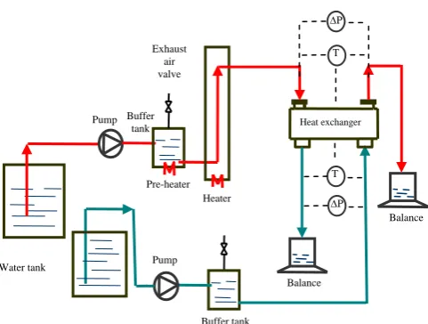
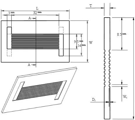
[image:2.595.303.544.89.271.2]Three major parts are used in the experimental system: the test section (the microchannel heat exchanger), syringe system, and overall testing loop, as shown in Fig. 1. In this study, two microchannel heat exchangers were tested. The heat transfer process of these devices is carried out between two liquids which are hot water and cold water; the hot and cold fluids are flowing in the opposite directions. Fig. 2 shows the dimensions of the test sections. The substrate material used for the heat exchangers is aluminum, with the thermal conductivity of 237 W/(mK), density of 2,700 kg/m3, and specific heat at constant pressure of 904 J/(kgK). For each microchannel heat exchanger, the top side for the hot water has 10 microchannels and the bottom side for the cold water also has 10 microchannels. The length of each microchannel is 32 mm. Microchannels have rectangular cross-section with the width and the depth being Wc and Dc, respectively. In a microchannel heat exchanger, all channels are connected by manifolds for the inlet and outlet of hot water and for those of cold water, respectively. The manifolds of the heat exchangers are of the same cross-sections: having a rectangular shape with a width of 3 mm and a depth of 300 m.
Fig. 1. Schematic of the test loop for microchannel heat exchangers
Fig. 2 shows the dimensions of the test section. In this study, two microchannel heat exchangers were designed and manufactured, with their dimensions listed in Table 1. Fig. 3 shows a photo of the microchannel heat exchanger. These test sections were manufactured by precision micromachining [3]. Each inlet hole or outlet hole of the heat exchangers has a cross-sectional area of 9 mm2. The four sides of the heat exchanger were thermally insulated by the glass wool with a thickness of 5 mm. To seal the microchannels, two layers of PMMA (polymethyl methacrylate) are bonded on the top and bottom sides of the substrate by UV (ultraviolet) light process, as indicated in Fig. 3. The physical properties of the PMMA and the glass wool are listed in Table 2 [14].
Water tank
Exhaust air valve
Pre-heater Heater
Buffer tank Pump
P
Balance
Heat exchanger
P T
Balance
Pump Buffer
tank
[image:2.595.320.532.368.440.2]T
Table 1. Geometrical parameters of microchannel heat exchangers
No.
Dimensions of the substrate (mm)
Dimensions of the channel
(m)
L W T Wc Dc
Fig. 2. Dimensions of the test section
[image:3.595.327.529.181.273.2]Fig. 3. A photo of the microchannel heat exchanger
Table 2. The physical properties of the PMMA and the glass wool
Experimental data for the microchannel heat exchanger were obtained under the constant room temperature of 25 ºC. For this study, DI water (deionized water) was used as the working fluid. Each inlet or outlet of the heat exchanger has a set of two thermocouples to record temperature values. So, there are eight thermocouples in total. At each side, a differential pressure transducer was used to measure the pressure drop. To assess the accuracy of measurements presented in this work, the uncertainty values for measured parameters are listed in Table 3. In addition, the uncertainties on the dimensions of microchannel evaluated by using a scanning laser made by Mitaka/Ryokosha model NH-3. The uncertainties of the scanning laser were estimated to be ± 0.03 µm. Equipments used for the experiments are listed as
1. Thermocouples, T-type
2. Pump, Model PU-2087, made by Jasco 3. Pump, VSP-1200, made by Tokyo Rikakikai 4. Heater, Model AXW-8, made by Medilab
5. Differential pressure transducer, Model PMP4110, made by Duck
6. Micro electronic balance, Model TE-214S, made by Sartorious.
Table 3. Uncertainty data for measured parameters
Parameter Uncertainties Temperature 0.1 C
Pressure 0.025% FS
Mass flow rate 0.0015 g Channel height 7 m Channel width 10 m Channel length 70 m
In order to study the effects of gravity on heat transfer and fluid flow behaviors of the heat exchangers, all experimental conditions for the two microchannel heat exchangers were kept the same. Throughout the paper, the experimental conditions of testing were discussed: the case is studied under condition of increasing the mass flow rate of the cold side. Further details of the case are as follows:
The inlet temperature and the mass flow rate of the hot side were fixed at 70 ºC and 0.2308 g/s, respectively; at the cold side, the inlet temperature was fixed at 22.5 ºC and the mass flow rates were varying from 0.2135 to 0.401 g/s.
B. Data analysis
In the following analyses, the major assumptions were made:
- The fluid is a laminar flow
- The fluid flow is incompressible and continuum - Heat transfer is steady
- Negligible radiation heat transfer.
For the experiments carried out in this study, the effects on the heat transfer and fluid flow – such as heat flux, effectiveness, pressure drop, and performance index – of the heat exchangers will be discussed as follows.
The maximum heat transfer rate, Qmax is evaluated by Qmax = (mc)min(Th,i – Tc,i) (1) The heat transfer rate of the heat exchanger, Q is calculated by
Qc = mccc (Tc,o – Tc,i) (2) The effectiveness (NTU method) is determined by
max Q
Qc
(3)
Heat flux is calculated by
c c
W A
Q q
c i c, o c, c c
nL
) T -(T c m
(4) Or q = kTlm=
R Tlm
(5) PMMA
Test sample
Material Density kg/m3
[image:3.595.74.261.338.448.2]The overall thermal resistance R is determined by
R = Rcond + Rconv (6) The log mean temperature difference is calculated by
max min max min ln lm T T T T T (7)
where m is mass flow rate (subscripts h and c stand for the hot side and cold side, respectively), n is number of microchannels, c is specific heat, Th,i, Th,o, Tc,i and Tc,o are inlet and outlet temperatures of the hot and cold sides, respectively, q is heat flux, A is heat transfer area, k is overall heat transfer coefficient,
cond
R is conductive thermal resistance, c h conv h h
R 1 1 is convective thermal resistance, hh and hcare the convective heat transfer coefficients of the hot side and the cold sides, respectively, is thickness of heat transfer, is thermal conductivity, and Tlmis the log mean temperature difference.
The Reynolds number is calculated by:
c c
h D W m wD 2
Re
(8)
where P A D c h 4
is the hydraulic diameter, w is velocity in the z-direction, is dynamic viscosity, is density, Ac is cross-sectional area, and P is wetted perimeter.
The total pressure drop of the heat exchanger is given by c
h
t p p
p
(9) where phand pcare pressure drops of hot and cold sides, respectively.
The performance index,
, is determined byc h t c p p p Q
mccc(Tc,o-Tc,i)
(10) The experimental uncertainties were estimated, following the method described by Holman [15]; the final expressions for uncertainties were given as follows:
2 / 1 2 , , , , 2 2 i c o c i c o c c c c c c Q T T T T c c m m Q U
c (11)
2 / 1 2 2 2 2 2 Re
Re
c c c c D D W W m m U (12) 2 / 1 2 2 2 , , , , 2 2 c c h h i c o c i c o c c c c c p p p p T T T T c c m m U
(13)
[image:4.595.313.540.398.582.2]By using the estimated errors of parameters listed in Table 3, the maximum experimental uncertainties in determining Qc, Re, and were 2,1%, 3.1%, and 3.3%, respectively, for all cases being studied.
III. RESULTSANDDISCUSSION
For the experimental system, the inlet temperature and the mass flow rate of the hot side were fixed at 70 ºC and 0.2308 g/s, respectively; at the cold side, the inlet temperature was fixed at 22.5 ºC and the mass flow rates were varying from 0.2135 to 0.401 g/s. In this study, influence of gravity was determined by two cases: one with horizontal channels, the other with vertical channels. For vertical channels, the hot water is flowing upward which is against the gravitational field, while the cold water is flowing downward which is in the same direction as the gravitational field. Two microchannel heat exchangers T1 and T2 were tested: these two microchannel heat exchangers have the same physical configurations for their substrates, manifolds, and lengths of channels; only the cross-sectional areas of microchannels are different. The microchannels of T1 have a rectangular cross-section with width of 500 m and depth of 300 m; the microchannel of T3, width of 500
m and depth of 180 m. Parameters of the heat exchangers (T1 and T2) are listed in more detail in Table 1.
36 38 40 42 44 46
0.1500 0.2000 0.2500 0.3000 0.3500 0.4000 0.4500
Mass flow rate of cold side , g/s
O u tl et t e m p e ra tu re o f h o t s id e, 0 C
T 1-horizont al T 1-vertical T 2-horizont al T 2-vertical
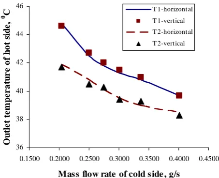
Fig. 4. Comparison of the outlet temperatures of hot side
38 40 42 44 46 48 50
0.1500 0.2000 0.2500 0.3000 0.3500 0.4000 0.4500
Mass flow rate of cold side, g/s
Ou
tl
et
t
em
p
er
a
tu
re o
f co
ld
s
id
e,
0 C
[image:5.595.314.545.59.246.2]T 1-horizontal T 1-vertical T 2-horizontal T 2-verticcal
Fig. 5. Comparison of the outlet temperatures of cold side
20 22 24 26 28 30
0.1500 0.2000 0.2500 0.3000 0.3500 0.4000 0.4500
H
e
at
t
r
an
sf
e
r
r
a
te
, W
Mass flow rate of cold side, g/s T1-horizontal
T1-vertical
T2-horizontal
[image:5.595.55.277.62.242.2]T2-vertical
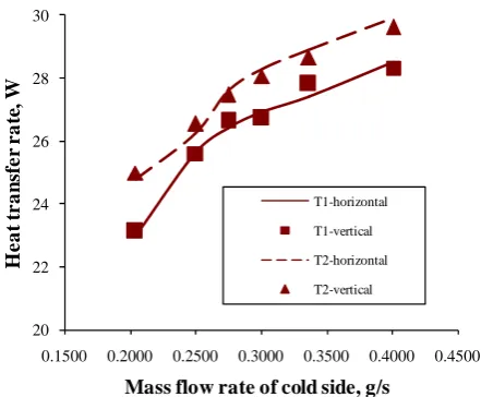
Fig. 6. Comparison of the heat transfer rates
The outlet temperatures of hot side obtained from T1 is higher than those obtained from T2; however, the outlet temperatures of cold side obtained from T1 is lower than those obtained from T2. As a result, the heat transfer rate obtained from T2 is higher than that obtained from T1, as shown in Fig. 6. The results obtained from the present study are in good agreement with those obtained from [8]. Foli et al. [8] indicated that under the constant mass flow rate condition, the higher the heat flux, the lower the aspect ratio (defined as the ratio of the microchannel height to its width). It is shown from Fig. 6 that the heat transfer rates obtained from horizontal channels and those from the vertical ones are negligibly small. The heat transfer rate of the heat exchangers is a function of the mass flow rate of cold side: it increases from 24.8 to 29.92 W with the mass flow rate of cold side rising from 0.2043 to 0.401 g/s (for the heat exchanger T2).
0 1000 2000 3000 4000 5000 6000
100 140 180 220 260 300
Re numbe r of cold side
T
o
ta
l p
res
su
re
d
ro
p
,
P
a
[image:5.595.314.538.302.490.2]T 1-horizontal T 1-vertical T 2-horizontal T 2-vertical
Fig. 7. Comparison of the total pressure drops
2 6 10 14 18 22
100 140 180 220 260 300
Re numbe r of cold side
P
e
rf
o
r
ma
n
c
e i
n
d
e
x
, W
/k
P
a
T 1-horizontal T 1-vertical T 2-horizontal T 2-vertical
Fig. 8. Comparison of the performance indices
Because that the hydraulic diameter of channel in T2 is smaller than that of channel in T1, this results in the velocity in the channel of T2 to be higher than that of T1, leading to a higher total pressure drop in T2 than that in T1, as shown in Fig. 7. Besides, the Figure shows that the total pressure drop is a function of Reynolds number of cold side; the total pressure drop increases as rising the Re number of cold side. Experimental results for effects of gravity on the behavior of pressure drop for the microchannel heat exchanger are also shown in Fig. 7. It is observed that the change of pressure drop between the two cases (horizontal channels and vertical channels) is negligibly small; the maximum change in pressure is 7.2% for a pressure drop from 1060 to 2044 Pa.
[image:5.595.60.281.303.485.2]heat exchanger T1, a performance index of 21.68 W/kPa was achieved for water from the hot side having an inlet temperature of 70 C and a mass flow rate of 0.2308 g/s and for water from the cold side having an inlet temperature of 22.5 C and mass flow rate of 0.2135 g/s. It is also observed that the change of performance between the two cases (horizontal channels and vertical channels) is negligibly small; the maximum change in performance is 5.5%, out of a performance index from 13.69 to 21.68 W/kPa.
In summary, it is concluded that the impact of gravity on the fluid flowing through the microchannel heat exchanger can be ignored as indicated in [8, 9, 13, 16].
IV. CONCLUSION
An experimental work was done on two microchannel heat exchangers to carry out the evaluation of their performance for the varying the mass flow rates of the cold side. These two microchannel heat exchangers have the same physical configurations for their substrates, manifolds, and lengths of channels; only the cross-sectional areas of microchannels are different.
For heat exchanger T1, a performance index of 21.68 W/kPa was achieved for water from the hot side having an inlet temperature of 70 C and a mass flow rate of 0.2308 g/s and for water from the cold side having an inlet temperature of 22.5 C and mass flow rate of 0.2135 g/s.
The impact of gravity on the fluid flowing through the microchannel heat exchanger was found to be small, with the maximum difference between the results of horizontal and vertical channels being less than 8%. In addition, in this study, good agreements were achieved between the results obtained from the present study and the results obtained from the literatures.
ACKNOWLEDGMENT
The supports of this work by (1) the project (Project No. NSC 99-2221-E-033-025) sponsored by National Science Council of the Republic of China in Taiwan and (2) the project (under Grant No. CYCU-98-CR-ME) sponsored by the specific research fields at Chung Yuan Christian University, Taiwan, are deeply appreciated.
REFERENCES
[1] W.J. Bowman and D. Maynes, A review of micro-heat exchanger flow physics, fabrication methods and application, Proceedings of ASME IMECE 2001, New York, USA, Nov 11-16, 2001, HTD-24280, pp. 385-407
[2] J.J. Brandner, L. Bohn, T. Henning, U. Schygulla, and K. Schubert, Microstructure heat exchanger applications in laboratory and industry, Proceedings of ICNMM2006, ICNMM2006-96017, Limerick, Ireland, 2006, pp. 1233-1243
[3] T.A. Ameel, R.O. Warrington, R.S. Wegeng, and M.K. Drost, Miniaturization technologies applied to energy systems, Energy Conversion and Management, Volume 38, 1997, pp. 969–982 [4] G.L. Morini, Single-phase convective heat transfer in microchannels: a
review of experimental results, International Journal of Thermal Sciences, Volume 43, Issue 7, 2004, pp. 631-651
[5] B. Mathew and H. Hegab, Application of effectiveness-NTU
relationship to parallel flow microchannel heat exchangers subjected to
external heat transfer, International Journal of Thermal Sciences, Volume 49, Issue 1, 2010, pp. 76-85
[6] S.W. Kang and S.C. Tseng, Analysis of effectiveness and pressure drop in micro cross-flow heat exchanger, Applied Thermal Engineering, Volume 27, Isuue 5-6, 2007, pp. 877-885
[7] R. Chein and J. Chen, Numerical study of the inlet/outlet arrangement effect on microchannel heat sink performance, International Journal of Thermal Sciences, Volume 48, Issue 8, 2009, pp. 1627-1638 [8] K. Foli, T. Okabe, M. Olhofer, Y. Jin, and B. Sendhoff, Optimization
of micro heat exchanger: CFD, analytical approach and multi-objective evolutionary algorithms, International Journal of Heat and Mass Transfer, Volume 49, Issue 5-6, 2006, pp. 1090-1099
[9] T.T. Dang, Y.J. Chang, and J.T. Teng, A study on the simulations of a trapezoidal shaped micro heat exchanger, Journal of Advanced Engineering, Volume 4, Issue 4, 2009, pp. 397-402
[10]T.T. Dang, J.T. Teng, and J.C. Chu, Effect of flow arrangement on the heat transfer behaviors of a microchannel heat exchanger, Proceedings of the International MultiConference of Engineers and Computer Scientists 2010, Hongkong, 2010, pp. 2209-2214
[11] T.T. Dang and J.T Teng, Influence of flow arrangement on the performance index for an aluminium microchannel heat exchanger, IAENG Transactions on Engineering Technologies Volume 5, the American Institute of Physics (AIP), Vol. 1285, 2010, pp. 576-590 [12] T.T. Dang and J.T. Teng, Effect of the substrate thickness of
counter-flow microchannel heat exchanger on the heat transfer behaviors, Proceedings of the international symposium on computer, communication, control and automation 2010, Taiwan, 2010, pp. 17-20 [13] T.T. Dang, J.T. Teng, and J.C. Chu, A study on the simulation and
experiment of a microchannel counter-flow heat exchanger. Applied Thermal Engineering, Volume 30, Issue 14-15, 2010, pp. 2163-2172 [14] COMSOL Multiphysics version 3.5 – Documentation, Sept 2008 [15] J.P. Holman, Experimental methods for engineers, McGraw-Hill, New
York, 1984