248
©IJRASET: All Rights are Reserved
Static Structural Analysis and Vibration
Optimization of Automotive Lower Control Arm
Mr. Mayur D. Patil1, Prof. Sanjay A. Pawar2 1
Department of Mechanical Engineering, FTC College of Engineering & Research, Sangola (Maharashtra).
2
Head of Mechanical Engineering Department, FTC College of Engineering & Research, Sangola (Maharashtra).
Abstract: The control arm is a unique type of independent suspension used in automobile vehicles. During the actual working condition, the maximum load is transferred from upper arm to the A arm which creates possibility of failure in the arm. Hence it is essential to focus on the stress analysis of a control arm to improve and modify the existing design. A control arm is an important part used in a suspension system of a car. Control arm performance is major role in managing the motion of the wheel during bump, turning, and breaking. This paper proposed the design optimization and modal analysis of steel cast for the front A control arm was investigated. CATIA software was utilized to design the A control arm. ANSYS 19 software was also used to analyze the structural strength and optimize the parts weight. The target of the new design was a 20% weight reduction from the existing part fabricated using steel material .testing and validation of new design using FFT analysis. Modal analysis carried out to find out natural frequencies of control arm and validation are done with the help of FFT analyzer and Impact Hammer Test.
Keywords: Static Structural Analysis, Optimization, FFT analyzer, Impact Hammer Test, CATIA
I. INTRODUCTION
The suspension system caries the vehicle body and transmit all forces between the body and the road without transmitting to the driver and passengers. The suspension system of a car is used to support its weight during varying road conditions. The suspension system is made of several parts and components. These include the front and rear. The suspension arm gets more attention by many researches like study dynamic analyses of the motor vehicle suspension system using the point-joint coordinate’s formulation. The mechanical system is replaced by an equivalent constrained system of particles and then the laws of particle dynamics are used to derive the equations of motion. Modeling and simulation are indispensable when dealing with complex engineering systems. It makes it possible to do an essential assessment before systems are developed. It can provide support in all stages of a project from conceptual design, through commissioning and operation. The most effective way to improve product quality and reliability is to integrate them in the design and manufacturing process.
Arm is one of the main components in the suspension systems. It can be seen in various types of the suspensions like wishbone or double wishbone suspensions. Most of the times it is called as A-type control arm. It joins the wheel hub to the vehicle frame allowing for a full range of motion while maintaining proper suspension alignment. Uneven tyre wear, suspension noise or misalignment, steering wheel shimmy or vibrations are the main causes of the failure of the A suspension arm. Most of the cases the failures are catastrophic in nature. So the structural integrity of the suspension arm is crucial from design point of view both in static and dynamic conditions. As the Finite Element Method (FEM) gives better visualization of this kind of the failures so FEM analysis of the stress distributions around typical failure initiations sites is essential. Therefore in this dissertation work it is proposed to carry out the structural analysis of A suspension arm of light commercial vehicle using FEM.
249
©IJRASET: All Rights are Reserved
II. LITERATUREREVIEW
Mohd Viqaruddin et. al [1] studied structural optimization of control arm for weight reduction and improved performance. The static analysis and torsion analysis of the control arm is done by using RADIOSS software. The high performance automotive and aerospace applications are the demand for reduced vehicle mass while maintaining adequate performance and safety. Formula SAE competition is no exception. Weight reduction is main objective of automotive industry. Topology optimization is defined as finding out the best possible solution of problem by considering the given sets of objective and number of constraints. For solving any topology optimization problem it has to specify three parameters that is design variables (material density), design objective (weight reduction) and design constraints (volume). Hence in order to accomplish the objective of weight reduction over existing design, finite element analysis method is used. While maintaining a critical factor of safety, FEA is used to remove the maximum amount of material from suspension system. The topology optimization given the idea of optimum material layout based on load & boundary conditions. Using optimum material layout, the component geometry is finalized by keeping the strength of component constant & 30% reduction in weight.
Do-Hyoung Kim et. al [2] carried out design of the composite suspension lower arm in combination with finite element analysis and design optimization. In this paper, an automotive composite lower arm was designed based on two kinds of analysis techniques (Riks and eigenvalue buckling analysis). In this paper, we designed an automotive composite lower arm using carbon-epoxy composite materials. To optimize the stacking sequence of the composite layer, we used a micro-genetic algorithm and investigated its effects on the performances of a lower arm, such as static/buckling load capability and stiffness. To maximize the buckling load capability, we performed the design optimization with the linear perturbation eigenvalue analysis, targeting a 50% weight reduction of conventional steel lower arm. We verified again the performance of the optimized composite lower arm using the static Riks analysis technique. Finally, we found that our composite lower arm had two times higher stiffness and buckling strength compared to the conventional steel lower arm while having 50% less weight.
Abhishek Mukund Puranik et. al [3] studied the performance of a vehicle is judged by driving comfort and safety, and both are provided by the suspension system. The suspension system is designed to carry the weight of vehicle and transmits al the forces between vehicle body and road. It is deals with finite element analysis for optimization of lower suspension arm of 4W suspension system. The main function of the lower suspension arm is to manage the motion of the wheels & keep it relative to the body of the vehicle. The optimization of lower suspension arm system is directly related to its strength or stiffness to with stand imposed force on the vehicle created by the road. Hence, Durability analyses and optimization is done in iterations, through Finite element method and computer aided engineering software’s it is possible to come out with new final optimized design of lower suspension arm. Therefore, topology optimization is carried out of the existing lower suspension arm at less stress concentrated area. As per the FEA analysis the lower suspension arm is being optimized by iterative method and thus optimizing the weight of the component.
Prashant Gunjan et. al [4] studied the important role of the suspension system is to compensate forces that occur as a result of the accelerations of the car. Also, it makes the vehicle more comfortable and safe. So, the optimal designed are required for better performance of existing design. The lower control arm is a type of independent suspension used in vehicles. During the actual working condition, the maximum load is transferred from upper arm to the lower arm which creates possibility of failure in the arm. It is essential to focus on the stress analysis of lower control arm to improve and modify the existing design. To analyze the lower control arm, ANSYS and FEA software is used. By using topology optimization technique the total deformation and mass will be reduced as compared to previous work. By reducing mass of the object and by suggesting the suitable material and design the production cost of lower control arm is reduced. This leads to cost saving and improved material quality of the product.
Swapnil S. Khode et. al [5] observed mostly all passenger cars and light trucks use independent suspension system because of inherent advantages over rigid suspension systems. Suspension system is the term given to the system of springs, shock absorbers and linkages that connect a vehicle to its wheels. Different optimization techniques under various load conditions have been widely used in automobile sector for lightweight and functioning enhancement. This study deals with Finite Element Analysis of the Lower control arm of Mac-pherson suspension system and its optimization under static loading condition. The main aim of this paper is to optimize the lower control arm of Mac-pherson suspension system under the current boundary conditions for weight reduction. The baseline model of the lower control arm is created by using solid modeling software viz. CATIA. ANSYS Workbench is used for Finite Element Analysis and OPTISTRUCT solver module is used to generate the optimized model. The present study is used to reduce the weight and cost of the lower control arm by keeping the factor of safety within permissible limits. The weight reduction in one lower control arm is observed to be 17.5%.
250
©IJRASET: All Rights are Reserved
in suspension system. In double wishbone suspension system both upper and lower control arm used. Modal analysis is done on control arm to find its natural frequency. By using the topology optimization technique, lower control arm is optimized & natural frequencies are extracted. After that the comparative study of existing and optimized lower control arm is undergone. Then optimized lower control arm is fabricated and tested using FFT analyzer.
Kale A. R [7] studied suspension arm is the main component in automotive suspension system. It carries all the different loads created due to irregular roads. There are various types of suspensions like wishbone or double wishbone suspensions. In the automotive industry, handling qualities of car is an important issue. These qualities are greatly affected by the suspension system. The aim of the paper is to analyze and optimize the lower arm using finite element analysis. The model of lower control arm is done in CAD software. Static analysis of lower control arm is carried out in analysis software. Some of the techniques consist of topology optimization, shape optimization, material substitution etc. Weight optimization of components for vehicles is becoming more important. The application of topology optimization is done for weight reduction. This method is efficiently applied to weight reduction on lower control arm.
III.PROBLEMSTATEMENT
Chassis parts are a critical part of a vehicle, leaving no room for error in the design and quality the present process relates to a computer-aided structure analysis and design graphic display device and method, and more particularly, to a computer-aided structure analysis of A control arm and which is analyzed and designed, thereby meet the customer requirements of LCA. This project is to optimize the A control arm by doe FFT analyzer and Impact Hammer Test by suggesting suitable material, and reducing sheet metal thickness, to reduce the batch production cost and to increase the strength of LCA.
IV.OBJECTIVES
A. To prepare CAD design using CATIA V5.
B. Static structural Analysis of Automotive A type control arm
C. Optimization of Automotive A type control arm.
D. To model analysis of the A type control arm using ANSYS Software.
E. Testing and validation of Automotive A type control arm with the help of FFT analyzer and Impact Hammer Test.
V. METHOLOGY
CAD modeling of existing Arm using CATIA
Finite Element Discretization using ANSYS
Applying boundary conditions
Modal Analysis - Natural frequencies and mode shapes for both original and optimized part
Using ANSYS solver to achieve topological optimization
Experimental Modal analysis using FFT analyzer and Impact hammer
Comparative analysis between FEA & Experimental results
Conclusion & Future scope
251
©IJRASET: All Rights are Reserved
VI.STATICANALYSIS
A. Material Properties 1) Steel
2) Modulus of Elasticity : 200GPa
3) Poisson’s ratio : 0.30
4) Density : 7.85e-6 kg/mm3
5) Yield Strength : 520 MPa
6) Mass of the body : 2.6042kg
B. Finite Element Analysis
Design of existing suspension control Arm is done by using CAD package CATIA V5 as per followin
Fig.No.2 Original Model
Fig.No.3Solid Mesh
C. Elements Details
1) Element Type: Tetrahedron
2) Element Order: second Order
3) Mesh Method: Solid
4) Node Population count: 154821
5) Element Population count: 80483
252
©IJRASET: All Rights are Reserved
a) Total weight of Indica = 1000kg=10000N (Approx)
b) Around 60 per load acts on front axle= 6000N
c) Load Acting on one ARM = 6000/2=3000N
Fig.No.5 Von-Mises Stress Original Model
Fig.No.6 Deformation Original Model
VII. OPTIMIZATION
Optimization is a process of determining the best design from a given design and material by applying loads and boundary conditions.
Mass of the body = 2.433kg
Fig.No.7 Optimized Model
253
©IJRASET: All Rights are Reserved
A. Elements Details
1) Element Type: Tetrahedron
2) Element Order: Second Order
3) Mesh Method: Solid
4) Node Population Count: 1288
5) Element Population Count: 696
Fig.No.9 Boundary Conditions Optimized Model
Fig.No.10 Von-Mises Stress Optimized Model
Fig.No.11 Deformation Optimized Model
254
©IJRASET: All Rights are Reserved
VIII. MODALANALYSIS
Every object has an internal frequency (or resonant frequency) at which the object can naturally vibrate. It is also the frequency where the object will allow a transfer of energy from one form to another with minimal loss. As the frequency increases towards the “resonant frequency,” the amplitude of response asymptotically increases to infinity. In other words, the results of the modal analysis are these frequencies at which the amplitude increases to infinity.
Every system can be described in terms of a stiffness matrix that connects the displacements and forces. These frequencies are known as natural frequencies of the system and are provided by the eigenvectors of the stiffness matrix. These frequencies are also known as the resonant frequencies.
Fig.No.13 model analysis mode 1
Fig.No.14 model analysis mode 2
255
[image:8.612.205.407.79.203.2]©IJRASET: All Rights are Reserved
Fig.No.16 model analysis mode 3
IX.EXPERIMENTALRESULTS
A. FFT Analysis
FFT is one main property in any sequence being used in general. To find this property of FFT for any given sequence, many transforms are being used. The major issues to be noticed in finding this property are the time and memory management. Two different algorithms are written for calculating FFT and Autocorrelation of any given sequence. Comparison is done between the two algorithms with respect to the memory and time managements and the better one is pointed. Comparison is between the two algorithms written, considering the time and memory as the only main constraints. Time taken by the two transforms in finding the fundamental frequency is taken. At the same time the memory consumed while using the two algorithms is also checked. Based on these aspects it is decided which algorithm is to be used for better results
DEWE-43 Universal Data Acquisition Instrument:
[image:8.612.185.429.426.557.2]When connected to the high speed USB 2.0 interface of any computer the DEWE-43 becomes a powerful measurement instrument for analog, digital, counter and CAN-bus data capture. Eight simultaneous analog inputs sample data at up to 204.8 kS/s and in combination with DEWETRON Modular Smart Interface modules (MSI) a wide range of sensors are supported Voltage Acceleration Pressure Force Temperature Sound Position RPM Torque Frequency Velocity And more The included DEWE Soft application software adds powerful measurement and analysis capability, turning the DEWE-43 into a dedicated recorder, scope or FFT analyzer.
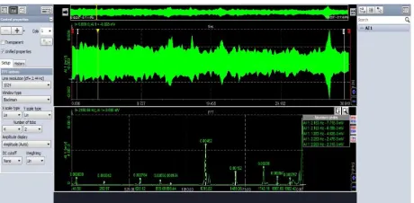
Fig.No.17 Experimental setup of FFT
B. Test FFT Results
[image:8.612.192.422.597.710.2]256
©IJRASET: All Rights are Reserved
X. RESULTS&DISCUSSIONS
1) After, Experimental testing is carried for static loading condition on suspension control Arm following Results obtained
Sr. No. suspension
control Arm
Existing Optimized
1. Von-Mises
Stress
240.62MPa 223.59MPa
2. Deformation 0.2254mm 0.2094mm
2) Weight Reduction of suspension control Arm
3) Comparative Plot of FEA VS FFT
Graph 1: Comparative Plot OF FEA VS FFT
XI.CONCLUSION
A. The suspension control Arm had the potential for optimization and weight reduction.
B. The optimized suspension control Arm is 6.53% lighter than the existing suspension control Arm. Both design produced stresses are within the yield limit 520 MPa of the material.
C. To model analysis of the A type control arm has done.
D. Natural Frequencies from modal analysis and FFT testing are in good relationship hence project is validated.
XII. ACKNOWLEDGMENT
It is of immense pleasure to me in expressing sincere and deep appreciation towards my guide Prof. S. A. Pawar., for priceless execution of steering this contribution all the way through this work with soft suggestions, embedded supervision and invariable advocacy. Special thanks to the principal and teaching staff of FTC, COER Sangola. for needful support and encouragement throughout the course.
suspension control Arm
Existing Optimized Weight reduction
% Weight reduction
257
©IJRASET: All Rights are Reserved
REFERENCES
[1] Mohd Viqaruddin, D.Ramana Reddy, “Structural optimization of control arm for weight reduction and improved performance,” Science Direct Materials Today: Proceedings 4 (2017) 9230–9236.
[2] Do-Hyoung Kim, Dong-Hoon Choi, Hak-Sung Kim, “Design optimization of a carbon fiber reinforced composite automotive lower arm,” Science Direct Composites: Part B 58 (2014) 400–407.
[3] Abhishek Mukund Puranik, Prof. V.M. Bansode, Prof. Sainand N. Jadhav , Asst. Prof. Y.C. Jadhav, “Durability Analysis and optimization of an Automobile Lower Suspension Arm Using FEA and Experiment Technique,” International Research Journal of Engineering and Technology (IRJET): Volume: 05 Issue: 09 Sep 2018.
[4] Prashant Gunjan, Amit Sarda,“ Design and Analysis of Front Lower Control Arm by Using Topology Optimization,” IJARIIE-ISSN(O)-2395-4396: Vol-4 Issue-2 2018.
[5] Swapnil S. Khode, Prof. Amol N. Patil, Prof. Amol B. Gaikwad, “Design Optimization of a Lower Control Arm of Suspension System in a LCV by using Topological Approach,” International Journal of Innovative Research in Science Engineering and Technology: Vol. 6, June 2017.
[6] Miss. P. B. Patil, Prof. M. V. Kharade, “ Finite Element Analysis and Experimental Validation of Lower Control Arm,” 2016 IJEDR: Volume 4, Issue 2, ISSN: 2321-9939.